a. Advanced Trainers: Aluminized finish except all-metal types, which will be natural metal finish,
b. Primary and Basic Trainers: Yellow and blue as required by Spec. 98-24113.
2. IDENTIFICATION NUMERALS FOR TRAINING AIRPLANES
a. The use of field numbers and the painting of ring cowls (or combination thereof) for identification purposes of Training airplanes at activities of the various Army A, C. Training Centers and Civil Flying Schools is authorized. Designation of these identification numbers and ring cowl colors for activities within each Training Center will be the responsibility of the respective Commanding General thereof. The identification numbers will be of a contrasting color, preferably block type, and will be applied to each side of the fuselage approximately midway between the vertical projections of the trailing edge of the wing and the leading edge of the horizontal stabilizers. The height of the identification numerals will be approximately three fourths of the projected height of the fuselage at this location.
|
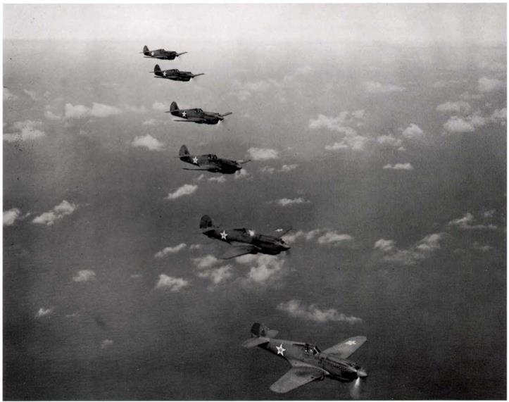
Six Curtiss P-40Cs of the 18th PG over Oahu, Hawaii, on August 1, 1941. The group consisted of the 6th, 19th, 44th, 73rd, and 78th PS. All, except the 44th PS, were caught on the ground on December 7,1941. Aircraft seen are numbered 41,47, 51,53, 54, and 43. (USAF)
|
3. COLORS FOR USE ON AIRPLANES IN ALASKAN DEPT. OR COUNTRIES HAVING SIMILAR CLIMATIC AND TERRAIN CONDITIONS.
a. To provide a color scheme offering marked contrast for spotting forced landings, etc. for airplanes operating in Alaska or in countries where like conditions prevail, the use on the top and bottom surfaces of wings of camouflage materials, of the shades covered in A. C. Bulletin No. 41, to best meet the conditions of local terrain color is authorized. Since the distribution of airplanes is not known at the time the respective manufacturers are camouflaging the finished airplanes, airplanes will necessarily be furnished with camouflage in accordance with A. C. Spec. 24114. It will therefore be necessary to apply any special colors where such special distinguishing colors are authorized. It will not be necessary to remove the original camouflage coating to apply the special colors. However, lacquer camouflage material cannot be applied over a previous coating of enamel camouflage material.
b^ When tactical requirements demand, airplanes operated in these locations will be maintained in a camouflaged condition as follows:
(1) Lower surfaces will be camouflaged as prescribed in A. C. Spec. 24114.
(2) Upper surfaces will be camouflaged with such shades of specified materials as best blend with the local terrain.
5, MARKINGS. – a. Each airplane and each lighter-than-air aircraft will be marked in accordance with Spec. Nos. 9824105 and 99-2050, respectively.
b. The code markings specified therein are the means by which the number, identity, and age of protective coatings of the airfoils, fuselage, etc., and other pertinent data relating to the aircraft, are determined. Therefore, in no instance will such marks be omitted or placed where they can not readily be seen when the aircraft is completely assembled.
c. Markings required by specifications will neither be altered nor effaced, except as required by repairs or refinishing operations, in which case the markings will be properly replaced, nor will they be transferred from locations designated in specifications.
d. 
There being no military reason for the use of individual names, the practice of naming airplanes after states, municipalities, or other localities will be discontinued. However, each airplane will have the name of the home station, in a contrasting color, placed on the left side of the fuselage immediately above the technical data legend using letters approximately one inch high, with the top of the letters toward the leading edge of the wing. These markings are to be centrally located with respect to the wing outline. The letters are to be of the vertical type, 24 inches high and with strokes four inches wide.
|
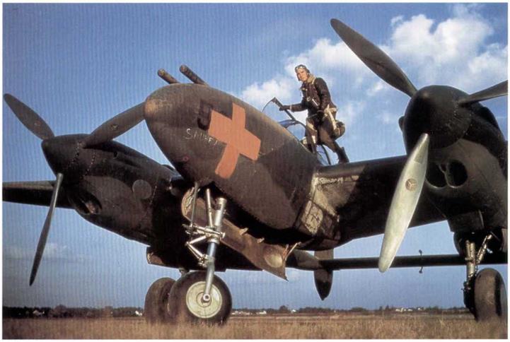
Lockheed P-38D, 5-1P, showing the red cross used in the 1941 Louisiana maneuvers. It carries the name “Snuff" on the nose in white. Note the unpainted propellers. (USAF via Gerry R. Markgraf)
|
|
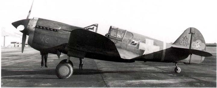
Curtiss P-40E of the 79th PS, 20th PG, Hamilton Field, at Oakland on December 6,1941. This is the Flight Leader’s aircraft, A Flight. The nose band and command stripe are in yellow no. 48. Propeller is still not camouflaged black, as ordered in May 1941. Fuselage cocarde is covered with a maneuver cross. The personal insignia on the rudder is a major exception to USAAF practice at that time. (F. Shertzer via William L. Swisher)
|
6, STANDARD INSIGNIA. – Air Corps standard insignia will be placed and maintained on each aircraft, as prescribed in Spec. 98-24102, or Spec. 24114 (camouflaged Airplanes),
7. ORGANIZATION INSIGNIA. – a. Definition. – Organization insignia are those designs, markings, etc., that have been approved by the War Department for use by an individual organization.
b. Rules governing Design, – The following rules govern the designs of Air Corps organization insignia:
(1) They will be simple and, where practicable, will depict some historical significance associated with the
organization,
(2) They will be dignified and in good taste. Fantastic designs may be characteristic and “funny” but have no permanent value.
(3) Each design w ill possess the clearness required to make it distinguishable at a distance of at least 150
yards.
(4) They will not contain —
Numerals
The letters “U. S.”
The Air Corps insignia.
The United States flag.
The United States coat of arms or any part of it.
The complete coat of arms of any state or country, although devices may be taken from them when applicable.
Outlines of geographical maps.
Foreign decorations (e. g, Croix de Guerre, Fourragere).
Campaign ribbons.
c. Submitting Samples for Approval. – Before placing a new design on equipment, three 8 by 10-l/2inch sample copies will be prepared on good quality paper and submitted, for approval, to the Adjutant General through the Chief of the Air Corps. The samples will be colored with water colors or wax crayons in the colors intended for the insignia when placed on the aircraft. Blends of color may be used when essential, but much better results are obtained when blends are not employed, as it is difficult to match or keep them uniform in shade or tint in each of the paintings on the several aircraft. The “poster” type of design and “block” coloring are recommended. A brief outline of the historical development or significance of the design will accompany the sample copies when submitted for approval. No variation from an approved design will be permitted without authority from the Adjutant General,
|
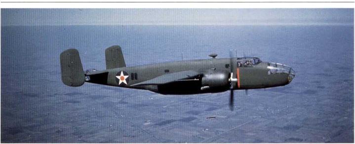
North American B-25Aon test flight over Los Angeles in pristine camouflage: note the red warning stripe in line with the propellers. (USAF via Gerry R. Markgraf)
|
d. Rules Governing Use. – The following rules govern the use of organization insignia on aircraft:
(1) Each aircraft assigned to a permanent organization, including U. S. Army A. C. schools, but not including Civil Flying Schools under contract, will bear the insignia of that organization, For example:
Aircraft assigned to a squadron will bear the insignia of that squadron.
Aircraft assigned to a headquarters of groups, wings, etc., will bear the insignia of such headquarters.
(2) No aircraft will bear organization insignia other than that of one organization.
(3) The placing of organization insignia on aircraft will be a responsibility of the organization to which the insignia pertain. Depots will not be required to reproduce insignia or other markings peculiar to an individual organization.
e. Location, Size, and Application for Airplanes, –
(1) It is impossible to specify a standard location for organization insignia on all airplanes; therefore, no specific locations are mandatory, However, the sides of the fuselage midway between the wings and tail surfaces are the most desirable and should be used whenever conditions permit, so that the insignia on the majority of airplanes will be in the same relative location. The spaces selected on the two sides of the fuselage should be as nearly as possible opposite each other, and should have smooth surfaces unbroken by fittings, lacing, fasteners, steps, joints, openings, etc. When avoidable, insignia will not be placed on cowling.
(2) In no instance will the size of an insignia exceed three fourths of the depth of the fuselage at the point at which the insignia is applied. Otherwise, the size will be governed by the most suitable spaces available, provided that such spaces are not too small or unfavorable for other reasons. If the available spaces are too small to provide visibility, as described in paragraph 7 b (3), or is unsuitable due to fittings, lacings, fasteners, etc., or corrugated metal, each insignia may be painted on a sheet of aluminum or suitable alloy of the desired shape and area and not more than 1/32-inch thick. All sharp comers and edges of such sheets will be rounded off. The sheets will then be secured to the sides of the airplane with screws, washers, and nuts, or by other suitable means, in a manner permitting ready removal when necessary. Each sheet will be secured at a sufficient number of points to prevent it being torn off in flight, and to prevent vibration that would cause it to crack or to wear the fabric or other parts. Whenever practicable, it will be secured to rigid members of the airplane. When necessary to attach such a sheet to fabric, the fabric will be adequately reinforced with tape securely attached by doping, and, if required, by stitching. In addition, suitable reinforcing strips of sheet metal or wood will be used next to the inside face of the fabric to receive the inside ends of the screws or other securing parts. Insignia on tike models of airplanes in the same organization should be uniform in size.
f. Location. Size, and Application for Lighter-than-Aircraft.
(1) Organization insignia will be placed on each-side of each lighter-than-aircraft. The locations for observation balloons will be on each side, halfway between the greatest diameter and the leading edges of the horizontal lobes. The locations for spherical balloons will be at points in line with and three feet from each end of the wording “U. S. Army.”
(2) In no instance will the size of lighter-than-air insignia exceed nine square feet. The insignia placed on each craft assigned to an organization will be uniform in size. However, this does not require that insignia of different organizations be of the same size.
(3) The insignia for all lighter-than-aircraft will be painted on two-ply envelope-fabric. Code No. IOI, and securely attached to the envelope with rubber cement. Each sheet of fabric will be neatly trimmed to the minimum size
|
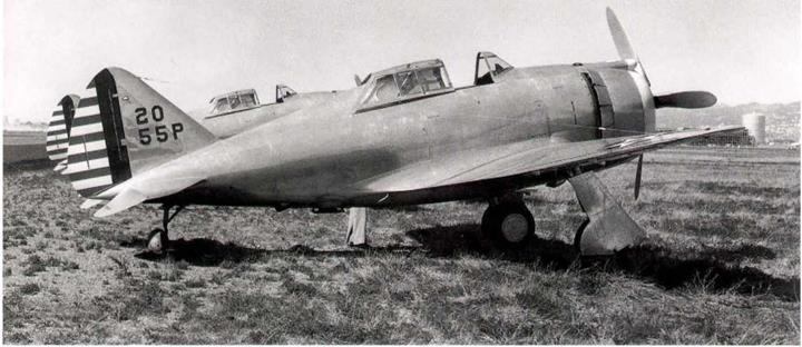
Republic P-43 (41-6674) of the 55th PG at Oakland in 1941. It was not camouflaged yet, because it was considered to be an interim type, not suitable for combat use overseas. The nose cowl is painted white. (F. Shertzer via William L. Swisher)
|
required, and, to insure adhesion, corresponding areas of the aluminum finish will be carefully removed from the envelopes with suitable wire brushes.
g. Decalcomania Insignia. – Where personnel are not available to paint organization insignia in a satisfactory manner, the use of decalcomania insignia on airplanes is authorized. Owing to the local nature of their usage, however it will be necessary for stations desiring to use these transfers to obtain them by local purchase. Their application does nol require skilled workmen, and when coated with clear varnish after being applied, they are about as durable as the average painted design. The cost varies with:
(1) Size
(2) Design
(3) The number ordered
(4) The number of colors and to some extent the colors themselves
Instructions for applying decalcomania are furnished by the manufacturer. Until used, the transfers should be stored in a dry place where they will not be exposed to temperatures abovenormal.
8. ORGANIZATION IDENTIFICATION. – as a means of identifying airplanes, allairplanes will be marked as outlined herein. These markings (paragraphs 8, 9, and 10) are in addition to the standard markings, insignia, and technical data prescribed in paragraphs 5, 6, and 7, and will be applied by the organization to which the airplanes are assigned,
a. Squadron Recognition Colors. – A suitable depth of the front portion of engine nacelles will be painted as follows:
(1) Pursuit. Attack and Bombardment Squadrons. – The cowling will be painted one solid color: red, white, blue or yellow. The assignment of colors will be made by the group commander except where, as a citation for distinguished service, an individual squadron may be authorized by higher authority to use other recognition markings.
(2) Group Headquarters and Headquarters Squadrons. –
(a) 3-Squadron Group. – The cowling to be divided by longitudinal lines into
three equal segments; one segment to be painted red, one white, and one
yellow,
(b) 4-Squadron Group, – The cowling to be divided by longitudinal lines into
four equal segments; one segment to be painted red, one white, one yellow, and one blue.
(3) Reconnaissance Squadrons.- The color or color combinations for painting
the cowling to be specified by wing commanders.
(4) Hq. Squadrons of Wings. Air Bases and G. H.O. AinForce, – No recognition colors to be employed.


Pursuit, Attack and Bombardment Squadrons,
Assignment of Colors in Group.
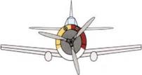
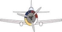
Group Headquarters and Headquarters Squadrons.
|

Squadron Command Airplanes
|
|
|

A1 Flight Command Airplanes
|
|
|

‘C Flight Command Airplanes
|
|
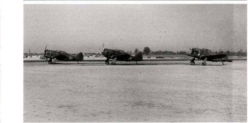
Republic P-43s of the 1st PG at the August 1941, Carolina maneuvers. Aircraft numbers 70, 73, and 74 of the group, they have finally been camouflaged, and carry the usual maneuvers red fuselage cross over the cocardes. (USAF)
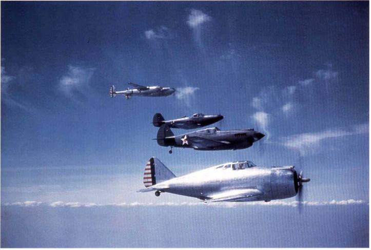
Republic YP-43, Curtiss P-40B, Bell P-39C and the second Lockheed YP-38 show the aircraft that had been selected in the Air Corps 1939 competition. The YP-38 and YP-43 are in natural metal and the P-39 and P-40 are camouflaged to Spec. 24114. In the event, all of these types proved to be disappointing performers, only the P-38 surviving in front line service until the end of the war. (LSAF via Gerry R. Markgraf)
b. Airplane Designators.
(1) Each airplane will have a distinctive designator assigned, which will consist of a combination of letters and numbers except airplanes on loan to civil flying-schools engaged under contract to train student Army pilots. The system of assigning the designators will use first the wing, group, squadron, corps area, or other unit identifying number, wherever applicable. This number will be followed by a letter or letters designating the type of equipment, as “B” for bombardment, “P” for pursuit, etc., or if not applicable, the assignment of the airplane as “W” for wing, “AB” for air base, “OR” for organized reserve, “AD” for air depot, etc., followed by a number which will be assigned by group and station commanders or by higher authority to designate a particular airplane. The following outlines the lettering system to be used,
|
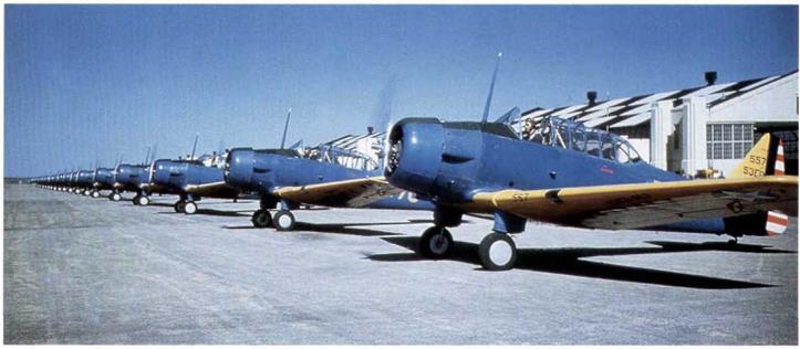
Colorful lineup of approximately 20 North America BC-ls. The nearest aircraft is marked 557 over 53ED on the tin. They are finished in the AN gloss true blue and gloss orange yellow colors. (USAF)
|
|
Activity
|
Svmbol
|
|
Air Base
|
AB
|
|
Air Depot
|
AD
|
|
Air Officer
|
AO
|
|
Bombardment Group
|
В
|
|
Communication Squadron
|
C
|
|
Headquarters
|
HQ
|
|
Instructor (miscellaneous)
|
IM.
|
|
Materiel Division
|
MD
|
|
Miscellaneous
|
M
|
|
National Guard
|
NG
|
|
Observation.
|
0
|
|
Organized Reserve
|
OR
|
|
Photo
|
PH
|
|
Pursuit Group
|
P
|
|
Reconnaissance
|
R
|
|
School
|
ED
|
|
Staff
|
S
|
|
Technical Supervisor
|
TS
|
|
Transport
|
T
|
|
Wing
|
w
|
|
Weather (Observation)
|
wo
|
(2) The following are examples of complete designators:
Activity Designator
Headquarters Squadron, GHQ Air Force HQ1 to HQ –
Headquarters Squadron, 2nd Wing 2W1 “ 2W –
5 th Air Base Squadron 5AB1 “ 5AB –
|
5th Bombardment Group.
|
9B1
|
it
|
9B-
|
|
20th Pursuit Group
|
20P1
|
tt
|
20P-
|
|
41st Reconnaissance Squadron
|
41RI
|
tt
|
41R –
|
|
4th Composite Group
|
4MB1
|
tt
|
4MB-
|
|
5 th Transport Squadron
|
6T1
|
tt
|
6T-
|
|
Fairfield Air Depot
|
FAD1
|
it
|
FAD-
|
|
Middletown Air Depot
|
MAD1
|
U
|
MAD-
|
|
Southeast Air Depot
|
SEAD1
|
tt
|
SEAD –
|
|
San Antonio Air Depot
|
SAADI
|
it
|
SAAD-
|
|
Sacramento Air Depot
|
SADI
|
“
|
SAD –
|
|
Panama Air Depot
|
PAD1
|
tt
|
PAD-
|
|
Hawaiian Air Depot
|
HADI
|
tt
|
HAD-
|
|
Phillippinc Air Depot
|
PHAD1
|
tt
|
PHAD-
|
|
2nd Corps Area Air Officer
|
2A01
|
tt
|
2AO –
|
|
1st Communications Squadron
|
1C1
|
it
|
1C-
|
|
National Guard Instructors
|
1M1
|
tt
|
Ш –
|
|
154th National Guard Observation Squadron54NGl Materiel Division
|
“ 54NG – MD1 “
|
MD –
|
|
22nd Observation Squadron, Air Corps
|
2201
|
tt
|
220-
|
|
1st Photo Squadron
|
1PH1
|
tt
|
1PH-
|
|
8th Corps Area Organized Reserve
|
80RI
|
tt
|
80R –
|
|
63rd School Squadron
|
63ED1
|
tt
|
63ED-
|
|
1st Staff Squadron
|
1S1
|
tt
|
IS-
|
|
Technical Supervisor
|
TS1
|
tt
|
TS-
|
|
2nd Weather Observation Squadron
|
2W01
|
tt
|
2WO-
|
|
Miscellaneous
|
Ml
|
tt
|
M –
|
* NOTE: Not inducted into Federal Service – All National Guard Squadrons are Observation, and with the NG symbol used it is not necessary to add the О symbol. Since all National Guard Units bear a squadron number between 100 to 199, the hundred designation will be dropped in the interest of brevity.
After induction into Federal Service – Federalized National Guard squadrons will use designators as specified for Air Corps Observation Squadrons, including the О symbol and the complete squadron number.
(3) In the case of a composite group, the airplane designator will consist of the group number, followed by the letter “M” for miscellaneous, a second letter to indicate the type of equipment, as “B” for bombardment, and the designating number of the particular airplane.
c. The letters and figures composing the airplane designators will be of the vertical block type, the width will be 2/3 of the height and the strokes will be approximately 1” wide for every 6" of height. The distance between the letters is equal to 1/2 the width of a letter. In consideration of the varied sizes and configurations of airfoils and fuselages of A. C. airplanes, it is impractical to specify a standard height of letters that will meet the requirements all airplanes. In general, however, the height of the letters and figures will be as specified in the following paragraphs and uniformity should be maintained for airplanes of similar types at a station. The airplane designators will be painted on in a centrally located position in the following locations:
(1) For airplanes not camouflaged. – The designator will appear on each side of the vertical stabilizer.
Where more than one vertical stabilizer is used, the designator will appear on the left exposed side of the left hand stabilizer and on the right exposed side of the right hand stabilizer. The lettering will appear in two lines with the individual airplane number on the top line, and the unit or organization designator on the bottom line and reading from left to right. For example, 12 indicating number “12” airplane of the 31st Pursuit Group. The letters and airplane numbers will be of sufficient height as to make the designator readily discernible from a distance of approximately 150 yards.
(2) For camouflaged airplanes. – The designator will be as specified in paragraph 8 c (1) for uncamouflaged airplanes, except that the necessary area of both the vertical stabilizer and the rudder be utilized.
(3) On the upper and lower sides of the left wing only (upper side of the left upper wing and the lower side of the left lower wing in the case of a biplane). The lettering will appear all on one line, with the top of the letters toward the leading edge.
(a) The upper surface markings will be centered on a line at right angles to the longitudinal axis of the airplane, and passing through the center of the Air Corps insignia. The height of the letters will be 1/5 of the chord of the wing, as measured at a point 3/4 of the distance from the fuselage to the inner edge of the Air Corps insignia.
(b) The lower surface markings will be ahead of and parallel to the word "Army.” The height of the letters will be 1/3 of that portion of the chord from the top of the letters composing the word "Army” to the center of the leading edge of the wing, as measured at a point 3/4 of the distance from the fuselage to the inner edge of the Air Corps insignia.
(4) In addition to the above, the airplane identification number (squadron, group or station) “12” in example cited in paragraph 4 с. (1), will be painted on the engine cowling, or on the forward portion of the fuselage, so as to be visible from the forward hemisphere. The variation in size and contour of the locations available for these identifying numbers will necessitate that the exact location and size of the numbers be determined locally for each model of airplane.
(5) The following colors will be used for these identifying markings.
(a) Black against a light background. In the case of camouflaged airplanes black, shade No. 44, Air Corps Bulletin No. 41.
(b) Yellow (Shade No. 4 for uncamouflaged airplanes – Shade No. 48, A. C. Bulletin No.4l, for camouflaged airplanes) against a dark ground.
|
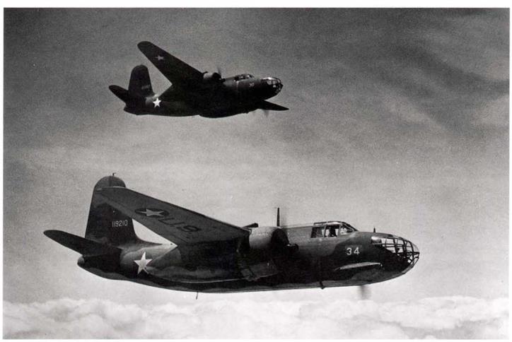
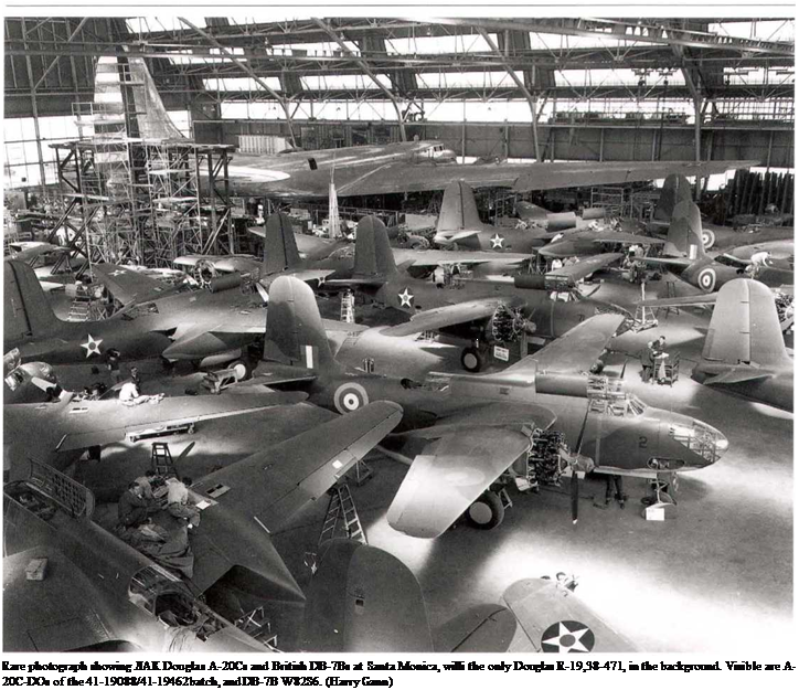
Douglas A-20C-DO, 41-19210, in formation with another. This was the AAF version of the RAF Boston Mk. III and was finished in the standard RAF day bomber camouflage of dark green and dark earth over sky. 808 were built at Santa Monica and 140 at Boeing, Seattle. (USAF)
|
9. COMMAND RECOGNITION STRIPES. – Command airplanes, except as noted in paragraph 9 c, will be identi
fied by painted stripes 5 inches wide, encircling the fuselage immediately back of the rear cockpit. These stripes will be of the same color as the squadron identification color, except that black will be used instead of blue on blue or camouflage fuselages, and instead of white on unfinished aluminum alloy fuselages. The number of stripes and their position on the fuselage will be as follows:
a. Squadron Command Airplanes. – Two stripes, five inches apart, encircling the fuselage in planes at right angles
to the axis of the airplane.
b. Flight Command Airplanes. –
A flight – One stripe encircling the fuselage in a plane at right angles to the axis of the airplane.
В Flight – One stripe encircling the fuselage at a 45° angle from the horizontal with the uppermost part of
the encircling stripe inclined toward the front of the airplane.
C Flight – One stripe encircling the fuselage at a 45° angle from the horizontal with the uppermost part of
the encircling stripe inclined toward the rear of the airplane.
c. Command identification stripes will not be employed by headquarters squadrons of
Air Bases, Wings, or the G. F1.Q. Air Force.
10. NAMES OF COMBAT CREW. – a. Door Type Airplanes. Names of permanently assigned members of the combat crew will be posted on the inside of the door. For a this purpose, a metal holder with celluloid cover, size approximately 5" x 7", containing a typed list of the combat crew will be utilized.
b. Cockpit Type Airplanes – Names of permanently assigned members of the combat crew to be stenciled or painted on the forward portion of the left side of the fuselage; letters to be approximately 1/2” in height; white, and on a black, rectangular background of suitable dimensions.
11. PAINTTQBEUSED.
a. On airplanes not camouflaged – – All painted insignia, organization identification colors, etc., enamel, Spec. 3-98, insignia colors in oil, Spec. 3-120, or lacquer, Spec. 3-158, will be used.
Jr. On camouflaged airplanes. – The only paints, regardless of the purpose for which used, that will be applied to the exterior surface of camouflaged airplanes, will be Air Corps camouflage materials, (Spec. Nos. 14105,14106 or 14109) and of colors covered by Air Corps Bulletin No. 41. Primer, metal, zinc chromate, Spec. 14080, will be used wherever a primer coat is required.
|
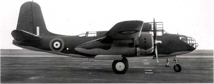
Douglas DB-7B, RAF Boston 111 (RAF serial number W8311) at Oakland in 1941, showing the RAF day bomber camouflage of dark earth and dark green over sky. 836 of this version were supplied to the RAF. (William L. Swisher)
|
|
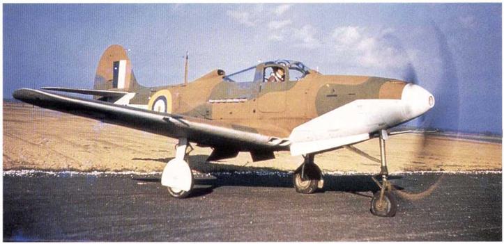
Beil Airacobra Mk 1 for RAF, AH62I, running up, shows its incorrect application of RAF fighter camouflage. The Dark Earth and Dark Green should come down to lower edge of nose and fuselage, not brought up to the center-line as seen. Sky was the underneath color. (USAF via Gerry R. Markgraf)
|
Camouflage Finishes for Aircraft (Specification 24114)
Anew Air Corps Spec. 24114 “Camouflage Finishes for Aircraft”, was issued as a result of the Air Corps Study No. 42 on camouflage of combat aircraft. Dated October 24, 1940, it also introduced Air Corps Bulletin No. 41, “Color Card for Camouflage Finishes”, (see Chapter 7) which established the new Air Corps matt colors for permanent camouflage paints. The key requirements of this specification were:
Application-
One coat of zinc chromate primer, Spec. 14080, shall be applied to all exterior surfaces. This shall be followed by two coats of camouflage lacquer, Spec. 14105, applied as follows: all upper surfaces except for insignia shall be coated with dark olive drab, Shade 41 of Bulletin 41, camouflage lacquer. The olive drab coating shall extend downward on the sides of the fuselage and all other similar surfaces in such manner than none of the neutral gray coating is visible when the airplane is in normal level flight attitude and is viewed from above from any direction within an angle of approximately thirty degrees from vertical lines tangent to the airplane. The location of the color boundary line in accordance with the foregoing shall be subject to the approval of the Procurement Agency. All under surfaces, except for insignia and markings, shall be coated with neutral gray, Shade 43 of Bulletin 41, camouflage lacquer. Masks shall not be employed to separate the two shades. The lines of demarcation shall be eliminated as far as possible by blending the colors at the junction line by over-spraying.
Finish of Fabric Covered Surfaces:
Apply at least three brushed coats of yellow or cream semi-pigmented nitrate dope. The dope shall not be thinned for brush application. Apply at least one spray coat of yellow or cream semi-pigmented nitrate dope, thinned as required for spray application. Apply at least two spray coats of dark olive drab or neutral gray fully pigmented nitrate camouflage dope as required.
|
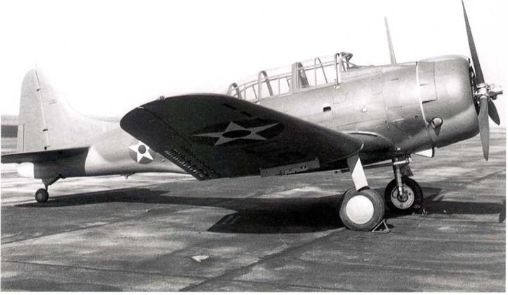
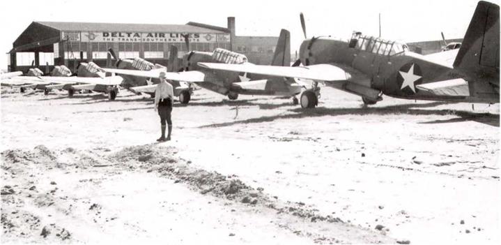
Douglas A-24 at Oakland in 1941. Three inch high letters on the tail show that this an SBD-3A (for Army) taken off the Navy line. Aircraft lacks the Navy arresting hook and has a pneumatic tire on the tail wheel, rather than the solid Navy tire. It is finished in dark olive drab and neutral gray, per Douglas finish drawing. (William L. Swisher)
|



 CHAPTER 3:1943—The Struggle for Air Superiority










 Ribs, Spars, and all interior structures Fuselage, excepting compartments for personnel, luggage and cargo Cockpits for pilots and observers which
 Material Command issues Military Requirements Policy No. 60, concerning AAF insignia on leased commercial aircraft, January 6, 1944.