Polaris Propulsion
Meanwhile, the navy’s Polaris missile had made more far-reaching contributions. Until Polaris A1 became operational in 1960, all U. S.
long-range missiles had used liquid propellants. These had obvious advantages in their performance, but their extensive plumbing and large propellant tanks made protecting them in silos difficult and costly. Such factors also made them impractical for use on ships. After the operational date of Minuteman I in 1962, the Department of Defense began phasing out liquid-propellant strategic missiles.34
 Meanwhile, given the advantages that liquid propellants enjoyed in terms of performance, their head start within the defense establishment, and the disinclination of most defenders of liquids to entertain the possibility that solid propellants could satisfy the demanding requirements of the strategic mission, how did this solid-propellant breakthrough occur? The answer is complicated and technical. But fundamentally, it happened because a number of heterogeneous engineers promoted solids; a variety of partners in their development brought about significant technical innovations; and although interservice rivalries encouraged the three services to development separate missiles, interservice cooperation ironically helped them do so. Despite such cooperation and the accumulating knowledge about rocket technology, however, missile designers still could not foresee all the problems that their vehicles would develop during ground and flight testing. Thus, when problems did occur, rocket engineers still had to gather information about what had caused problems and exercise their ingenuity to develop solutions that would cope with the unexpected.
By the time that Polaris got under way in 1956 and Minuteman in 1958, solid-propellant rocketry had already made the tremendous strides forward discussed previously. But there were still enormous technical hurdles to overcome. The problems remaining to be solved included higher performance; unstable combustion; the inadequate durability of existing nozzle materials under conditions of heat and exposure to corrosive chemicals from the exhaust of the burning propellants; a lack of materials and technology to provide light but large combustion chambers so the burning propellants had to overcome less mass during launch; and ways to terminate combustion of the propellant immediately after the desired velocity had been achieved (for purposes of accuracy) and to control the direction of the thrust (for steering).35
Once the navy had overcome the bureaucratic obstacles to developing its own, solid-propellant missile, the Special Project Office (SPO) under Adm. William F. Raborn and Capt. Levering Smith achieved breakthroughs in a number of these technical areas. In early January 1956, the navy had sought the assistance of the Lockheed Missile and Space Division and the Aerojet General Corpora-
tion in developing a solid-propellant ballistic missile. The initial missile the two contractors and the SPO conceived was the Jupiter S (for “solid"). It had enough thrust to carry an atomic warhead the required distance, a feat it would achieve by clustering six solid rockets in a first stage and adding one for the second stage. The problem was that Jupiter S would be about 44 feet long and 10 feet in diameter. An 8,500-ton vessel could carry only 4 of them but could carry 16 of the later Polaris missiles. With Polaris not yet developed, the navy and contractors still were dissatisfied with Jupiter S and continued to seek an alternative.36
One contribution to a better solution came from Atlantic Research Corporation (ARC). Keith Rumbel and Charles B. Henderson, chemical engineers with degrees from MIT who were working 240 for ARC, had begun theoretical studies in 1954 of how to increase Chapter 6 solid-propellant performance. They learned that other engineers, including some from Aerojet, had calculated an increase in specific impulse from adding aluminum powder to existing ingredients. But these calculations had indicated that once aluminum exceeded 5 percent of propellant mass, performance would again decline. Hence, basing their calculations on contemporary theory and doing the cumbersome mathematics without the aid of computers, the other researchers abandoned aluminum as an additive except for damping combustion instability. Refusing to be deterred by theory, Rumbel and Henderson tested polyvinyl chloride with much more aluminum in it. They found that with additional oxygen in the propellant and a flame temperature of at least 2,310 kelvin, a large percentage of aluminum by weight yielded a specific impulse significantly higher than that of previous composite propellants.37
ARC’s polyvinyl chloride, however, did not serve as the binder for Polaris. Instead, the binder used was a polyurethane material developed by Aerojet in conjunction with a small nitropolymer program funded by the Office of Naval Research about 1947 to seek high-energy binders for solid propellants. A few Aerojet chemists synthesized a number of high-energy compounds, but the process required levels of heating that were unsafe with potentially explosive compounds. Then one of the chemists, Rodney Fischer, found “an obscure reference in a German patent" suggesting “that iron chelate compounds would catalyze the reaction of alcohols and isocyanates to make urethanes at essentially room temperature." This discovery started the development of polyurethane propellants in many places besides Aerojet.
In the meantime, in 1949 Karl Klager, then working for the Office of Naval Research in Pasadena, suggested to Aerojet’s parent
firm, General Tire, that it begin work on foamed polyurethane, leading to two patents held by Klager, along with Dick Geckler and R. Parette of Aerojet. In 1950, Klager began working for Aerojet. By 1954, he headed the rocket firm’s solid-propellant development group. Once the Polaris program began in December 1956, Klager’s group decided to reduce the percentage of solid oxidizer as a component of the propellant by including oxidizing capacity in the binder, using a nitromonomer as a reagent to produce the polyurethane plus some inert polynitro compounds as softening agents. In April 1955, the Aerojet group found out about the work of Rumbel and Henderson. Overcoming explosions due to cracks in the grain and profiting from other developments from multiple contributors, they discovered successful propellants for both stages of Polaris A1.
 These consisted of a cast, case-bonded polyurethane composition including different percentages of ammonium perchlorate and aluminum for stages one and two, both of them featuring a six-point, internal-burning, star configuration. With four nozzles for each stage, this propellant yielded a specific impulse of almost 230 lbf – sec/lbm for stage one and nearly 255 lbf-sec/lbm for stage two. The latter specific impulse was higher in part because of the reduced atmospheric pressure at the high altitudes where it was fired, compared with stage one, which was fired at sea level.38
The addition of aluminum to Aerojet’s binder essentially solved the problem of performance for Polaris. Other innovations in the areas of warhead size plus guidance and control were necessary to make Polaris possible, but taken together with those for the propellants, they enabled Polaris A1 to be only 28.6 feet long and 4.5 feet in diameter (as compared with Jupiter S’s 44 feet and 10 feet, respectively). The weight reduction was from 162,000 pounds for Jupiter S to less than 29,000 pounds for Polaris. The cases for both stages of Polaris A1 consisted of rolled and welded steel. This had been modified according to Aerojet specifications resulting from extensive metallurgical investigations.
Each of the four nozzles for stage one (and evidently, stage two as well) consisted of a steel shell, a single-piece throat of molybdenum, and an exit-cone liner made of “molded silica phenolic between steel and molybdenum." A zirconium oxide coating protected the steel portion. The missile’s steering came from jetavators designed by Willy Fiedler of Lockheed, a German who had worked on the V-1 program during World War II and had developed the concept for the device while employed by the U. S. Navy at Point Mugu Naval Air Missile Test Center, California. He had patented the idea and then adapted it for Polaris. Jetavators for stage one were molybdenum
FIG. 6.4
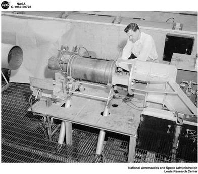 An unidentified solid-rocket motor being tested in an altitude wind tunnel at NASA’s Lewis Research Center (later Glenn Research Center) in 1959, one kind of test done for Polaris. (Photo courtesy of NASA)
rings with spherical inside surfaces that rotated into the exhaust stream of the four nozzles and deflected the flow to provide pitch, yaw, and roll control. The jetavators for stage two were similar.39
Besides requiring steering, the missile needed precise thrust termination when it reached the correct point in its trajectory. This could be achieved on liquid-propellant missiles simply by stopping the flow of propellants. For solids, the task was more difficult. The Polaris team used pyrotechnics to blow out plugs in six ports in front of the second stage at the proper moment in the trajectory. This permitted exhaust gases to escape and halt the acceleration so that the warhead would travel on a ballistic path to the target area.40
Flight testing of Polaris revealed, among other problems, a loss of control due to electrical-wiring failure at the base of stage one. This resulted from aerodynamic heating and a backflow of hot exhaust gases. To diagnose and solve the problem, engineers in the program obtained the help of “every laboratory and expert," using data from four flights, wind tunnels, sled tests, static firings, “and a tremendous analytic effort by numerous laboratories." The solution placed fiberglass flame shielding supplemented by silicone rubber over the affected area to shield it from hot gases and flame.41
Another problem for Polaris to overcome was combustion instability. Although this phenomenon is still not fully understood,
gradually it has yielded to research in a huge number of institutions, including universities and government labs, supported by funding by the three services, the Advanced Research Projects Agency, and NASA. Levering Smith credited Edward W. Price in the Research Department at NOTS with helping to understand the phenomenon. By this time, Price had earned a B. S. in physics and math at UCLA. In February 1960, he completed a major (then-classified) paper on combustion instability, which stated, “This phenomenon results from a self-amplifying oscillatory interaction between combustion of the propellant and disturbances of the gas flow in the combustion chamber." It could cause erratic performance, even destruction of motor components. Short of this, it could produce vibrations that would interfere with the guidance/control system. To date, “only marginal success" had been achieved in understanding the phenomenon, and “trial-and-error development continues to be necessary." But empirical methods gradually were yielding information, for example, that energy fluxes could amplify pressure disturbances, which had caused them in the first place.42 The subsequent success of Polaris showed that enough progress had been made by this time that unstable combustion would not be a major problem for the missile.
 Long before Polaris A1 was operational, in April 1958 the DoD had begun efforts to expand the missile’s range from the 1,200- nautical-mile reach of the actual A1 to the 1,500 nautical miles originally planned for it. The longer-range missile, called Polaris A2, was originally slated to achieve the goal through higher-performance propellants and lighter cases and nozzles in both stages. But the navy Special Projects Office decided to confine these improvements to the second stage, where they would have greater effect. (With the second stage already at a high speed and altitude when it began firing, it did not have to overcome the weight of the entire missile and the full effects of the Earth’s gravity at sea level.) Also, in the second stage, risk of detonation of a high-energy propellant after ignition would not endanger the submarine. Hence, the SPO invited the Hercules Powder Company to propose a higher-performance second stage.43
As a result, Aerojet provided the first stage for Polaris A2, and Hercules, the second. Aerojet’s motor was 157 inches long (compared with 126 inches for Polaris A1; the additional length could be accommodated by the submarines’ launch tubes because the navy had them designed with room to spare). It contained basically the same propellant used in both stages of Polaris A1 with the same grain configuration. Hercules’ second stage had a filament-wound case and a
cast, double-base grain that contained ammonium perchlorate, nitrocellulose, nitroglycerin, and aluminum, among other ingredients. The grain configuration consisted of a 12-point, internal-burning star. It yielded a specific impulse of more than 260 lbf-sec/lbm under firing conditions. The motor was 84 inches long and 54 inches in diameter, featuring four swiveling nozzles with exit cones made of steel, asbestos phenolic, and Teflon plus a graphite insert.44
This second-stage motor resulted from an innovation that increased performance by adding ammonium perchlorate to the cast, double-base process used in Hercules’ third stage for the Vanguard launch vehicle. Hercules’ ABL developed this new kind of propellant, known as composite-modified double base (CMDB), by 1958, evidently with the involvement of John Kincaid and Henry Shuey, 244 developers of the earlier cast, double-base process.45
Chapter 6 Even before 1958, however, Atlantic Research Corporation had developed a laboratory process for preparing CMDB. In its manufactured state, nitrocellulose is fibrous and unsuitable for use as an unmodified additive to other ingredients being mixed to create a propellant. Arthur Sloan and D. Mann of ARC, however, developed a process that dissolved the nitrocellulose in nitrobenzene and then separated out the nitrocellulose by mixing it with water under high shear (a process known as elutriation). The result was a series of compact, spherical particles of nitrocellulose with small diameters (about 1 to 20 microns). Such particles combined readily with liquid nitroplasticizers and crystalline additives in propellant mixers. The result could be cast into cartridge-loaded grains or case-bonded rocket cases and then converted to a solid with the application of moderate heat. Sloan and Mann patented the process and assigned it to ARC. Then, in 1955, Keith Rumbel and Charles Henderson at ARC began scaling the process up to larger grain sizes and developing propellants. They developed two CMDB formulations beginning in 1956. When ARC’s pilot plant became too small to support the firm’s needs, production shifted to Indian Head, Maryland. Because the plastisol process they had developed was simpler, safer, and cheaper than other processes then in existence, Henderson said that Hercules and other producers of double-base propellants eventually adopted his firm’s basic method of production.
Engineers did not use it for upper stages of missiles and launch vehicles until quite a bit later, however, and then only after chemists at several different laboratories had learned to make the propellant more rubberlike by extending the chains and cross-linking the molecules to increase the elasticity. Hercules’ John Allabashi at ABL began in the early 1960s to work on chain extenders and
cross-linking, with Ronald L. Simmons at Hercules’ Kenvil, New Jersey, plant continuing this work. By about the late 1960s, chemists had mostly abandoned use of plastisol nitrocellulose in favor of dissolving nitrocellulose and polyglycol adipate together, followed by a cross-linking agent such as isocyanate. The result was the type of highly flexible CMDB propellant used on the Trident submarine- launched ballistics missiles beginning in the late 1970s.46
 Meanwhile, the rotatable nozzles on the second stage of Polaris A2, which were hydraulically operated, were similar in design to those already being used on the air force’s Minuteman I, and award of the second-stage contract to Hercules reportedly resulted from the performance of the third-stage motor Hercules was developing for Minuteman I, once again illustrating technology transfer between services. (Stage one of the A2 retained the jetavators from A1.) The A2 kept the same basic shape and guidance/control system as the A1, the principal change being more reliable electronics for the guidance/control system. By the time Polaris A2 became operational in June 1962, now-Vice Admiral Raborn had become deputy chief of naval operations for research and development. In February
1962, Rear Adm. I. J. “Pete" Gallantin became director of the Special Projects Office with Rear Adm. Levering Smith remaining as technical director.47
As a follow-on to Polaris A2, in September 1960, Secretary of Defense Robert McNamara approved development of a 2,500-nautical – mile version of Polaris that became the A3. To create a missile that would travel an additional 1,000 nautical miles while being launched from the same tubes on the submarine as the A1 required new propellants and a higher mass fraction. The new requirement also resulted in a change from the “bottle shape" of the A1 and A2 to a shape resembling a bullet. In the attempt to help increase the mass fraction, Aerojet, the first-stage manufacturer, acquired the Houze Glass Corporation at Point Marion, Pennsylvania, and moved that firm’s furnaces, patents, technical data, and personnel to the Aerojet Structural Materials Division in Azusa, California, in early
1963. This acquisition gave Aerojet the capability to make filament – wound cases like those used by Hercules on stage two of Polaris A2. The new propellant Aerojet used was a nitroplasticized polyurethane containing ammonium perchlorate and aluminum, configured with an internal-burning, six-point star. This combination raised the specific impulse less than 10 lbf-sec/lbm.48
Unfortunately, the flame temperature of the new propellant was so high that it destroyed the nozzles on the first stage. Aerojet had to reduce the flame temperature from a reported 6,300°F to slightly
less than 6,000°F and to make the nozzles more substantial, using silver-infiltrated tungsten throat inserts to withstand the high temperature and chamber pressure. As a result, the weight saving from using the filament-wound case was lost in the additional weight of the nozzle. Hence, the mass fraction for the A3’s first stage was actually slightly lower than that for the A2, meaning that the same quantity of propellant in stage one of the A3 had to lift slightly more weight than did the lower-performing propellant for stage one of the A2.49
For stage two of the A3, Hercules used a propellant containing an energetic high explosive named HMX, a smaller amount of ammonium perchlorate, nitrocellulose, nitroglycerin, and aluminum, among other ingredients. It configured this propellant into an in – 246 ternal-burning cylindrical configuration with many major and mi – Chapter 6 nor slots in the aft end of the stage, creating a cross section that resembled a Christmas-tree ornament. This propellant offered a significantly higher specific impulse than stage two of Polaris A2. Also, the new stage two used a different method of achieving thrust vector control (steering). It injected Freon into the exhaust, creating a shock pattern to deflect the stream and achieve the same results as movable nozzles at a much smaller weight penalty.
A further advantage of this system was its lack of sensitivity to the temperature of the propellant flame. The Naval Ordnance Test Station performed the early experimental work on this use of a liquid for thrust vector control. Aerojet, Allegany Ballistics Laboratory, and Lockheed did analytical work, determined the ideal locations for the injectors, selected the fluid to be used, and developed the injectors as well as a system for expelling excess fluid. The Polaris A3 team first successfully tested the new technology on the second stage of flight A1X-50 on September 29, 1961. This and other changes increased the mass fraction for stage two of Polaris A3 to 0.935 (from 0.871 for stage two of the A2), a major improvement that together with the increased performance of the new propellant, contributed substantially to the greater range of the new missile.50


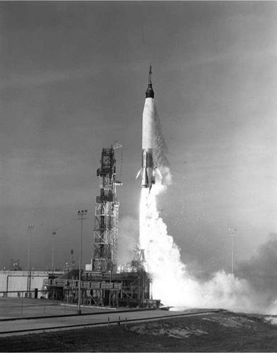
 One major area of difference between missile and launch-vehicle development lay in the requirement for special safeguards on launch vehicles that propelled humans into space. Except for Juno I and Vanguard, which were short-lived, among the first U. S. space-launch vehicles were the Redstones and Atlases used in Project Mercury and the Atlases and Titan IIs used in Project Gemini to prepare for the Apollo Moon Program. Both Projects Mercury and Gemini required a process called “man-rating" (at a time before there were women serving as astronauts). This process resulted in adaptations of the Redstone, Atlas, and Titan II missiles to make them safer for the human beings carried in Mercury and Gemini capsules.
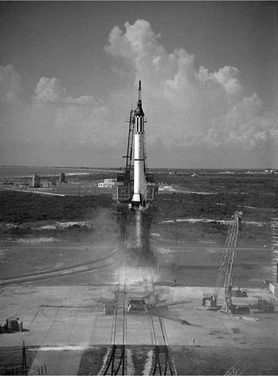 May 5, 1961, from Pad 5 at Cape Canaveral. (Photo courtesy of NASA)
 For Titan II-Gemini, there were major problems with longitudinal oscillations in the engines, known as pogo (from their resemblance to the gyrations of the then-popular plaything, the pogo stick). These never occurred in flight but appeared in a severe form during static testing of second-stage engines. Surges in the oxidizer feed lines were causing the problem, which Martin engineers and others solved with suppression mechanisms. There was also the issue of combustion instability that occurred on only 2 percent of the ground tests of second-stage engines. But for man-rating, even this was too high. Aerojet (the Titan engine contractor) solved the problem with a new injector.6
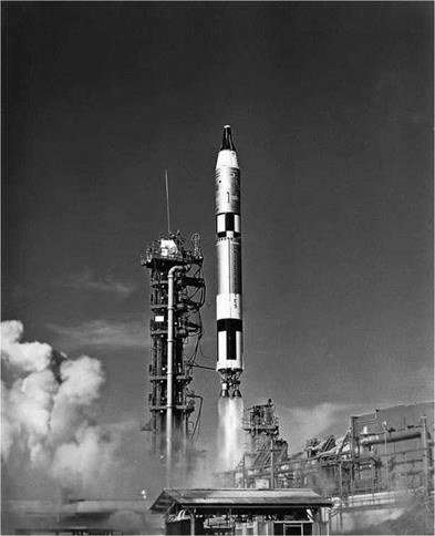
 In addition to a malfunction detection system, features added to the Titan II missile for astronaut safety included redundant components of the electrical systems. To help compensate for all the weight from the additional components, engineers also deleted vernier and retro-rockets, which were not necessary for the Gemini mission.8 From March 23, 1965, to November 11, 1966, Gemini 3 through 12 all carried two astronauts on the Gemini spacecraft. These missions had their problems as well as their triumphs. But with them, the United States finally assumed the lead in the space race with its cold-war rival, the Soviet Union. Despite lots of problems, Gemini had prepared the way for the Apollo Moon landings and achieved its essential objectives.9
 Despite the problems with the second stage of Vanguard, the air force used a modified version on its Thor-Able launch vehicle, showing the transfer of technology from the navy to the air service. The Able was more successful than the Vanguard prototype for two reasons. One was special cleaning and handling techniques for the propellant tanks that came into being after Vanguard had taken delivery of many of its tanks. Also, Thor-Able did not need to extract maximum performance from the second stage as Vanguard did, so it did not have to burn the very last dregs of propellant in the tanks. The residue that the air force did not need to burn contained more of the scale from the tanks than did the rest of the propellant. Consequently, the valves could close before most of the scale entered the fuel lines, the evident cause of many of Vanguard’s problems.30
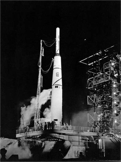
 Long before the final launch of the Thor-Able, nevertheless, the Department of Defense’s Advanced Research Projects Agency had
 Meanwhile, in the fall of 1959 Bell began designing the engine for the Agena D, which became the standard Agena propulsion unit. From June 28, 1962, to May 25, 1972, a large number of Thor-Agena D launches occurred, but because of the classified nature of many of the payloads, a reliable and precise tally is not available. During this period, the basic booster changed from the thrust-augmented to the long-tank, thrust-augmented Thor (called Thorad) with increased burning time and improved strap-on boosters.21
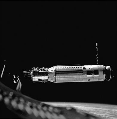 denberg AFB into sun-synchronous orbits, one of them a mission failure. The spacecraft were classified at the time but appear to have been Block 4A Defense Satellite Applications Program weather satellites used to inform the U. S. military of weather conditions for launching reconnaissance satellites and other defense purposes, such as mission planning during the conflict in Vietnam. In 1973, the program became the Defense Meteorological Satellite Program (DMSP) and was no longer classified.22
 A final major Thor launch vehicle was the Thor-Delta. Whereas the other Thor-based launch vehicles were primarily air force assets sometimes used by NASA, Delta was a NASA-developed space – launch vehicle used on occasion by the air force until near the end of the period covered by this book, when the air force began to make extensive use of Delta IIs. Since it was conceived by NASA in 1959 as an interim vehicle to lift medium payloads by using existing technology, modified only as needed for specific missions, Delta has enjoyed a remarkably long career, attesting to its success.26
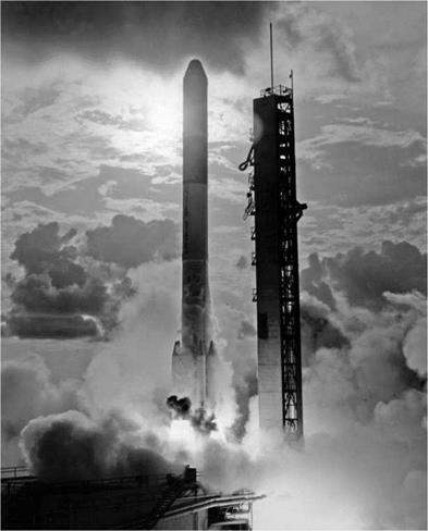


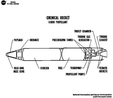
 Although there were other important upper-stage engines using storable propellants, such as the Bell Agena engine (starting with the 8048 model), the most significant engines with hypergolic propellants were those used in the Titans II, III, and IV, designed and built by Aerojet. Here, the previous experience with Vanguard, Able, and Able-Star undoubtedly were extraordinarily valuable, as was Aerojet’s involvement with the development of UDMH. In the latter development, Aerojet propellant chemist Karl Klager had been an important contributor. Klager held a Ph. D. in chemistry from the University of Vienna (1934) and had come to this country as part of Project Paperclip quite independently of the von Braun group. He worked for the Office of Naval Research in Pasadena during 1949 and started with Aerojet in 1950. The following year, Aerojet received a contract to develop an in-flight thrust-augmentation rocket for the F-86 fighter. The device never went into production, but in developing it, Aerojet engineers conducted a literature search for candidate propellants, did theoretical performance calculations, and measured physical and chemical properties in the laboratory. Together with RFNA, UDMH seemed highly promising but was not available in sufficient quantities to be used. Klager devised (and patented) production processes that yielded large quantities at reasonable prices, but workers began to get violently ill from the toxic substance. All did recover, and Aerojet learned how to control exposure to the vapors.37
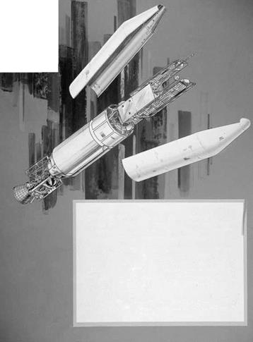
 Agena and its payload ride into space aboard a large booster rocket. Following staging, the Agena engine "first-burn" maneuvers the vehicle and its payload into an earth – oriented parking orbit. The Agena "second-burn" is geared to each particular mission – for example, an elliptical earth orbit or the ejection of a payload on a trajectory to the moon or planets.
 In May 1960, the air force signed a letter contract with the Martin Company to develop, produce, and test the Titan II. On October 9, 1959, Aerojet had already won approval to convert the Titan I engines to burn storable propellants. Research and development to that end began in January 1960. The Aerojet engineers also worked to achieve the improved performance called for in the April 30, 1960, plan for Titan II. Although the Titan II engines were based on those for Titan I, the new propellants and the requirements in the April 30 plan necessitated considerable redesign. Because the modifications did not always work as anticipated, the engineers had to resort to empirical solutions until they found the combinations that worked correctly and provided the necessary performance. Since the propellants were hypergolic, there was no need for an igniter in the Titan II engines (called XLR87-AJ-5 for the two engines in stage one and XLR91-AJ-5 for the single stage-two engine). The injectors for the Titan I engines had used alternating fuel and oxidizer passages with oxidizer impinging on oxidizer and fuel on fuel (called like-on – like) to obtain the necessary mixing of the two propellants. For the Titan II, Aerojet engineers tried fuel-on-oxidizer impingement. This evidently mixed the droplets of propellant better because higher performance resulted. But the improvement led to erosion of the injector face, necessitating a return to the like-on-like pattern.
 A 1965 Aerojet news release on Titan II propulsion credited it to “the efforts of hundreds of men and women" but singled out four of them as leaders of the effort. Three of their biographies illustrate the way that engineers in aerospace migrated from one firm to another or from government work to the private sector, carrying their knowledge of various technologies with them. Robert B. Young was the overall manager of the design, development, and production effort for both Titan I and Titan II. He was a chemical engineering graduate of Caltech, where Theodore von Karman had encouraged him to devote his knowledge to rocketry. He had worked for a year as director of industrial liaison on the Saturn program at NASA’s Marshall Space Flight Center, during part of the Titan years, and had risen within Aerojet’s own structure from a project engineer to a vice president and manager of the Sacramento, California, plant. Another leader was Ray C. Stiff Jr., who had discovered aniline as a hypergolic propellant while working at the navy Engineering Experiment Station in Annapolis. His role in the use of self-igniting propellants in JATOs to assist a PBY into the air while carrying heavy loads proved a forerunner “of the storable, self-igniting propellants used to such advantage in the Titan II engine systems." Stiff served as Aerojet’s manager of Liquid Rocket Operations near Sacramento and was also a vice president.
 Although the standpipe later proved to be part of the solution to the pogo problem, initially it seemed to make matters worse. Installed on missile N-11, flying on December 6, 1962, it failed to suppress severe oscillations that raised the gravitational effect from pogo alone to ±5 Gs. This lowered the chamber pressure to the point that instrumentation shut down the first-stage engine prematurely. The following mission, N-13, on December 19, 1962, did not include the standpipe but did have increased pressure in the fuel tank, which had seemed to be effective against the pogo effect on earlier flights. Another new feature consisted of aluminum oxidizer feed lines in place of steel ones used previously. For reasons not fully understood, the pogo level dropped and the flight was successful.
 A final problem that occurred in flight testing and required reengineering involved the gas generator in the stage-two engine. This issue was a matter of concern to the Titan II Program Office at BSD, not just to SSD and NASA. Engineers and managers first became aware there was a problem on the second Titan II test flight (June 7, 1962) when telemetry showed that the second-stage engine had achieved only half of its normal thrust soon after engine start. When the tracking system lost its signal from the vehicle, the range safety officer caused cutoff of the fuel flow, making the reentry vehicle splash down well short of its target area. The data from telemetry on this flight were inadequate for the engineers to diagnose the problem. It took two more occurrences of gas-generator problems to provide enough data to understand what was happening. Particles were partially clogging the small openings in the gas generator’s injectors. This restricted propellant flow and resulted in loss of thrust. Technicians very thoroughly removed all foreign matter from components of the generators in a clean room before assembly, separated the generators from the engines in transport, and subjected the assemblies to blowdown by nitrogen before each test flight to ensure no foreign particles were present.
 Despite this preparatory work for Minuteman, the missile did not begin formal development until the air force secured final DoD approval in February 1958. Meanwhile, civilian engineers employed by the air force at the Non-Rotating Engine Branch at Wright-Patterson AFB had continued efforts to develop large, solid-propellant motors. Perhaps from sources at Aerojet, they learned about adding large quantities of aluminum to a solid propellant to increase its performance. They combined this with other information they had been gathering on solid propellants while Hall was still with the branch. Bill Fagan from the branch carried this information to Hall at the Ballistic Missile Division (as the WDD had become).52
 Among many other difficulties, a major concern was launching from a silo. The first successful launch of the missile occurred in early February 1961, which Phillips referred to as “December 63rd" since the planned date had been in December 1960. It and two succeeding launches took place from a surface pad and were so successful that the team advanced the first silo launch to August 1961. The missile blew up in the silo, giving credence to critics in STL who had argued that firing a missile from a silo was impossible. As Phillips said, the missile “really came out of there like a Roman candle."57
 For stage two of Minuteman I, Aerojet used the polyurethane binder employed in Polaris, with ammonium perchlorate as the oxidizer and aluminum powder the major fuel. It used two slightly different propellant grains, with a faster-burning inner grain and a slower-burning outer one. The combination resulted in a conversion of the four-point, star-shaped, internal-burning cavity to a cylindrical one as the propellant burned, avoiding slivers of propellant that did not burn. The propellant yielded a vacuum specific impulse of nearly 275 lbf-sec/lbm at temperatures ranging from 60°F to 80°F.62
 MINUTEMAN II
 It frequently happens in the history of technology that innovations occur to different people at about the same time. This appears to have been the case with CTPB, which Aerojet historians attribute to Phillips Petroleum and Rocketdyne without providing details. These two companies may have been the source for information about the CTPB that Aerojet used in Minuteman II, stage two. Like Thiokol, in any event, Aerojet proposed to use MAPO as a cross-linking agent. TRW historians state that their firm’s laboratory investigations revealed the hydrolysis problem. They state that “working with Aerojet’s research and development staff," they developed “a formulation that eliminated MAPO. . . ." The CTPB that resulted from what apparently was a multicompany development effort had better fuel values than previous propellants, good mechanical properties such as the long shelf life required for silo – based missiles, and a higher solids content than previous binders. The propellant consisted primarily of CTPB, ammonium perchlorate, and aluminum. It yielded a vacuum specific impulse more than 15 lbf-sec/lbm higher than the propellant used in stage two of Minuteman I, Wing II.68
 Minuteman III featured multiple, independently targetable reentry vehicles with a liquid fourth stage for deployment of this payload. This last feature was not particularly relevant to launch-vehicle development except that the added weight required for it necessitated higher booster performance. Stages one and two did not change from Minuteman II, but stage three became larger. Hercules lost the contract for the larger motor to Aerojet. Subsequently, Thiokol and a new organization, the Chemical Systems Division of United Technologies Corporation, won contracts to build replacement motors. Stage three featured a fiberglass motor case, the same basic propellant Aerojet had used in stage two only in slightly different proportions, a single nozzle that was fixed in place and partially submerged into the case, a liquid-injection thrust-vector-control system for control in pitch and yaw, a separate roll-control system, and a thrust-termination system.
 The system for Minuteman III involved six circular-shaped charges on the forward dome. Using data from high-speed films and strain gauges, the Minuteman team learned that this arrangement worked within 20 microseconds, cutting holes that resulted in a rupture of the pressure vessel within 2 additional milliseconds. But the case developed cracks radiating from the edge of the holes. TRW used a NASTRAN computer code to define propagation of the cracks. It then determined the dome thickness needed to eliminate the failure of the fiberglass. Aerojet wound “doilies" integrally into the dome of the motor case under each of the circular charges. This eliminated the rupturing, allowing the system to vent the pressure in the chamber and produce momentary negative thrust.74
 The intellectual push for Centaur came from Convair Division of General Dynamics engineer Krafft Ehricke, who had worked for von Braun at Peenemunde and Huntsville and for Bell Aircraft before moving to Convair. When General Dynamics managers asked him to design an upper stage for Atlas, he and some other engineers, including Bossart, decided that liquid hydrogen and liquid oxygen were the propellants they needed. Aware to some degree that liquid hydrogen’s very low density, extremely cold boiling point (-423°F), low surface tension, and wide range of flammability made it unusually difficult to work with, Ehricke faced funding limitations under an air force contract that precluded performing as many tests as the propellant required—an important restriction on normal rocketengineering practice.38
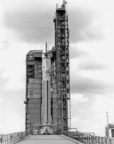
 The first use of the Centaur D-1A and SLV-3D was on the launch of Pioneer 11, which had the same mission as Pioneer 10 plus making detailed observations of Saturn and its rings. As on Pioneer 10, the mission also employed the Star 37 motor in a third stage. Launched on April 5, 1973, Pioneer 11 returned much data about Saturn, including discoveries of Saturn’s 11th moon and two new rings. Between 1973 and May 19, 1983, 32 SLV-3Ds launched with Centaur
 Partway through the history of Centaur and the various Atlas models used to launch it, the air force contracted with General Dynamics, beginning on February 14, 1966, to modify Atlas Es and Fs that had been in storage since their decommissioning as missiles in 1965. The process began with the newer F models. Rocketdyne inspected each of the MA-3 engines and fixed or replaced any part that failed to meet specifications. In 1969, the rocket division started a more extensive program of refurbishment to ensure that the engines in storage would work when called upon. After two launch failures in 1980-81, Rocketdyne rebuilt the engines at its plant, performing static tests before installing them on a launch vehicle.47
 Conceived as a missile, the Atlas became a successful and versatile launch vehicle, mated with a great variety of upper stages. Featuring a controversial but “brilliant, innovative, and yet simple" concept (the steel-balloon tank design), both the Atlas and the Centaur proved to be flexible and effective. With commercialization, the Atlas and the Centaur continued to provide launch-vehicle services beyond the period of this book and into the 21st century. The Centaur proved to be especially difficult to develop because of the peculiar properties of liquid hydrogen. But it was also hampered by initial funding arrangements and other avoidable problems. As with many rocket programs, engineers found that the existing fund of knowledge was inadequate to predict all of the problems that would occur in developing and launching an extraordinarily complex machine. Unforeseen problems continued into the 1990s, and engineers had to relearn the lesson that continual and sophisticated testing was the price of success, even if it did not always preclude unanticipated failures.54
 On July 23, 1963, Aerojet had successfully operated a Transtage engine for 4 minutes, 44 seconds, considered “a long duration firing." During that static test, the engine started and stopped three times, demonstrating the restart capability. However, a more critical test of this crucial capability (which would allow it to place multiple satellites into different orbits on a single launch or to position a single satellite in a final orbit, such as a geostationary orbit, without a need for a separate kick motor) would occur in the simulated-altitude test chamber at Arnold Engineering Development Center in Tullahoma, Tennessee. In August 1963, tests at that center confirmed suspicions from the July 23 test that the combustion chamber would burn through before completing a full-duration firing (undefined). In addition, gimballing of the engine in a cold environment revealed a malfunction of a bipropellant valve (that fed propellants to the combustion chamber) and a weakness in the nozzle extension, made of aluminide-coated columbium and radiation cooled with an expansion ratio of 40:1. Information about how Aerojet solved these problems is not available in any of the sources for this book, with the official history of the Titan III merely stating that “by the close of 1963, an extensive redesign and testing program was underway to eliminate these difficulties so the contractor could make his first delivery of flight engine hardware—due in mid – December 1963." 55
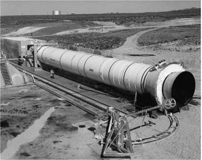
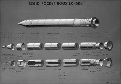
 The nozzle was partially submerged, and for gimballing, it used the Flexseal design Thiokol had scaled up in the 156-inch motor testing from the Lockheed’s Lockseal design. It was capable of eight degrees of deflection, necessitated among other reasons by the shuttle’s now-familiar roll soon after liftoff to achieve its proper trajectory. Having less thrust, the space shuttle main engines were incapable of achieving the necessary amount of roll, and the liquid-injection thrust-vector-control system used on the Titan solid – rocket motors would not have met the more demanding requirements of the shuttle. Hence the importance of the Lockseal-Flexseal development during the Large Segmented Solid Rocket Motor Program supported by both NASA and the air force.28
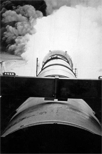
 Even early in launch-vehicle history, some missile programs had already begun to influence solid-propellant developments. In 1956, a creative group of engineers at Langley’s Pilotless Aircraft Research Division (PARD) began formulating ideas that led to the Scout launch vehicles. This group included Maxime A. Faget, later famous for designing spacecraft; Joseph G. Thibodaux Jr., who promoted the spherical design of some rocket and spacecraft motors beginning in 1955; Robert O. Piland, who put together the first multistage rocket to reach the speed of Mach 10; and William E. Stoney Jr., who became the first head of the group responsible for developing the Scout, which he also christened. Wallops, established as a test base for the National Advisory Committee for Aeronautics’ (NACA) Langley Memorial Aeronautical Laboratory in 1945, had a history of using rockets, individually or in stages, to gather data at high speeds on both aircraft models and rocket nose cones. These data made it possible to design supersonic aircraft and hypersonic missiles at a time when ground facilities were not yet capable of providing comparable information. It was a natural step for engineers working in such a program to conceive a multistage, hypersonic, solid-propellant rocket that could reach orbital speeds of Mach 18.32