Category Energiya-Buran

Introducing liquid hydrogen

Glushko’s initial position was to use only hydrocarbon fuels in the RLA family and introduce liquid hydrogen (LH2) at a later stage, when the technology was ripe.

Glushko had always disliked liquid hydrogen. In the 1960s he had opposed the use of liquid hydrogen on the upper stages of the N-1 rocket, arguing that the low density of hydrogen required large tanks and worsened the rocket’s mass characteristics. At an August 1974 meeting where Glushko outlined his plans for the RLA rocket family, several participants urged him to move to liquid hydrogen straightaway, but Glushko remained adamant [38]. At another meeting he reportedly said:

“The person who can find a way of building a rocket suited for the orbiter but

with the use of oxygen-kerosene will become my deputy’’ [39].

However, by the end of the year Glushko had to yield to the pressure. On 30 Novem­ber 1974 MOM minister Sergey Afanasyev signed an order to start the development of powerful cryogenic engines [40].

Despite Glushko’s wariness, Energomash had already performed some initial research on LOX/LH2 engines. In 1967 Glushko had tabled a proposal for a 200 to 250-ton cryogenic engine for the N-1 and a similar proposal had come from the Kuznetsov bureau [41]. Then there were studies at Energomash of two cryogenic engines for the RLA family, namely the RD-130 (200-ton vacuum thrust) in 1973 and the RD-135 (250-ton vacuum thrust) in 1974 [42]. Actually, the original idea was that Energomash would go on to build the engine, but the bureau was too preoccupied with the development of the powerful LOX/kerosene engines. Therefore, the task was entrusted to the Chemical Automatics Design Bureau (KB Khimavtomatiki or KBKhA) in Voronezh (the former “Kosberg bureau’’). The deal was that KBKhA in turn would hand over to Energomash the development of a 85-ton thrust LOX/ kerosene engine for the second stage of the medium-lift 11K77 (“Zenit”) rocket [43].

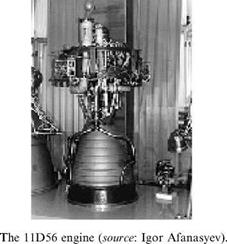
KBKhA was not the most obvious choice. First, the only space-related engines developed by KBKhA before this had been LOX/kerosene upper stages for R-7 derived launch vehicles and engines burning storable propellants for the second and third stages of the Proton rocket. Second, there were two design bureaus in the Soviet Union that had already pushed research on LOX/LH2 engines beyond the drawing board. These were KB Khimmash (the “Isayev bureau’’) and KB Saturn (the “Lyulka bureau’’), both of which had developed cryogenic engines for the upper stages of the N-1 (the 7.5-ton thrust 11D56 of KB Khimmash and the 40-ton thrust 11D54 and 11D57 of KB Saturn). One can only speculate that Glushko had second thoughts about relying on design bureaus that had been involved in the N-1, a rocket he wanted to erase from history.

Not only was KBKhA a newcomer to the field of LOX/LH2, it was now supposed to build from scratch a cryogenic engine several times more powerful than any developed in the Soviet Union before. With an anticipated vacuum thrust of 250 tons, the engine (called RD-0120) would even outperform the Space Shuttle Main Engine, which was related to the fact that the Russians had to compensate for the higher latitude of the Baykonur cosmodrome. Not surprisingly, KBKhA engineers began their work on the RD-0120 by consulting specialists from KB Khimmash and KB Saturn. They also extensively analysed the data available on the Space Shuttle Main Engines [44]. They almost certainly also benefited from the preliminary

image44

research done by Energomash on the RD-135, which had exactly the same perform­ance characteristics as the original version of the RD-0120.

THE RD-0120 ENGINE

The RD-0120 (also labelled 11D122), developed at the Chemical Automatics Design Bureau (KBKhA) in Voronezh, was a LOX/LH2 engine with a vacuum thrust of 190 tons and a vacuum specific impulse of 454 s. It was a staged combustion cycle engine in which the gases from the gas generator are cycled back into the main combustion chamber for complete combustion. The propellants first passed through low-pressure turbopumps (“boost pumps’’) that boosted the pressure significantly to prevent cavitation of the main turbopump assembly. The low-pressure hydrogen pump used a gas turbine driven by gaseous hydrogen from the main chamber cooling loop. The low-pressure oxygen pump had a hydraulic turbine powered by liquid oxygen.

Each RD-0120 had a single-shaft turbopump consisting of a two-stage axial turbine, a three-stage hydrogen pump, and two oxygen pumps. One of the oxidizer pumps was intended to feed the main combustion chamber and the other to feed the gas generator and the hydraulic turbine of the low-pressure oxygen pump. The 32,500 rpm turbopump was driven by a single fuel-rich preburner operating at 530°C.

mi

The RD-0120 engine (source: KBKhA).

During ascent the RD-0120 could be gimbaled plus or minus 11 degrees in pitch and yaw to help steer the rocket. Each engine was gimbaled with the help of two hydraulic servoactuators developed by KB Saturn (the “Lyulka bureau”), with hydraulic pressure being provided by pumps driven by high-pressure hydrogen gas from the engine itself. The engine could be throttled over a range of 45 to 100 percent, a significantly higher throttlability than the Space Shuttle Main Engine (SSME) (67-104%). The pneumatic control system included pressure helium bottles, pneumatic and electro-pneumatic valves, and system piping.

Nominal burn duration was between 450 and 500 seconds, although this could be significantly extended in case one engine had to compensate for the loss of another. The RD-0120 engines for the first three flightworthy Energiya rockets (6SL, 1L, and 2L) were certified for a total burn time of 1,670 seconds (230 seconds for test firings, 480 seconds for the launch, and 960 seconds back-up capability). This was increased to 2,000 seconds for flight vehicle 3L. Theoretically, this meant the engine could be reused for about three to four missions, although they were of course destroyed on re-entry together with the core stage. However, there were plans to certify the engines for 10 to 20 missions for reusable versions of Energiya and for possible use on foreign reusable launch vehicles. It was also planned to gradually uprate the engine, increas­ing the vacuum thrust to 230 tons and the vacuum specific impulse to 460.5 s. One of the modifications would have been the inclusion of an extendable nozzle to prevent loss of specific impulse in vacuum conditions.

Although the RD-0120 was built to the same overall performance specifications as the SSME, it certainly was not a copy of the SSME, differing from it in several important aspects. Also, the Russians could draw on their extensive experience with staged-combustion cycle engines used on the Proton rocket and various inter­continental missiles. While the RD-0120 had a single turbopump assembly both for liquid oxygen and hydrogen, the SSME has separate turbopumps for each propellant. Soviet engineers did consider a similar scheme, but opted for the single turbopump system because it simplified the computer control system and the ignition sequence. The RD-0120 had a channel-wall nozzle with fewer parts and welds than the SSME nozzle and was therefore easier to manufacture. In the late 1990s NASA even considered building a similar nozzle for the SSME, eliminating the tubular construction as a potential source of nozzle leaks. The new nozzle was also expected to have a higher degree of reusability [2].

Thermal control

The Thermal Control System (STR) had two internal and two external loops. Each loop operated completely independently, with pumps circulating cooling agents through it. The cooling agents were substances known as “Antifreeze-20” for the internal loops and “PMS-1.5” for the external loops. The internal loops maintained proper temperature (18-28°C) and humidity (30-70%) in the crew compartment, collected excess heat from equipment inside and just outside the crew compartment, and then transferred that heat to the external loops via liquid-to-liquid heat ex­changers. The external loops removed heat from systems in the unpressurized part of Buran (including the fuel cells, the hydraulic system, the payload, the maneuvering and attitude control engines) and finally delivered the excess heat to three types of

“heat sinks”: the radiator panels on the payload bay doors, flash evaporators, and ammonia boilers.

The eight radiator panels (one on each payload bay door) were the primary means of heat rejection in orbit. Just as on the Shuttle Orbiter, the two forward panels on each side could be unlatched and tilted to allow heat to be radiated from both sides of the panel. The fixed aft panels only dissipated heat from the outer side. When the payload bay doors were closed, heat loads from the external coolant loops were rejected by the flash evaporators or ammonia boilers, which cooled the loops by evaporating water and ammonia, respectively, and venting the resulting gases overboard. Water for this purpose was produced by the fuel cells and stored in the tanks of the Process Water System, whereas the ammonia was loaded in two small tanks prior to launch. The flash evaporators were apparently used during launch and the initial part of re-entry, but since water evaporation becomes ineffec­tive under higher atmospheric pressure, the ammonia boilers took over at an altitude of 35 km [19].

DOCKING AND EXTRAVEHICULAR ACTIVITY (EVA)

For space station missions Buran would have carried a Docking Module (SM) in the forward part of the payload bay. It consisted of a spherical section (2.55 m in diameter) topped by a cylindrical tunnel (2.2 m in diameter) with an APAS-89 androgynous docking port, a modified version of the APAS-75 system developed by NPO Energiya for the 1975 Apollo-Soyuz Test Project. The spherical section, bolted to the floor of the cargo bay, had two side hatches, one connecting it to Buran’s mid-deck and the other providing access to the payload bay for spacewalking cosmonauts or to a Spacelab-type module. The tunnel provided the actual interface between the Docking Module and the target vehicle and would be extended to its full length after opening of the payload bay doors. With the tunnel fully extended, the adapter was 5.7 m high. If the extendible part of the tunnel became stuck in its

Buran’s Docking Module (source: www. buran. ru).

deployed position, it could be pyrotechnically separated to allow the crew to close the payload bay doors.

At least one flightworthy SM was built for the first mission of flight vehicle nr. 2, which would have featured a docking with Mir and a Soyuz TM spacecraft. The Buran Docking Module served as the basis for a small module that was supposed to be attached to the Mir-2 space station to act as a berthing place for Soyuz, Progress, and Buran vehicles and as an airlock for spacewalks. It would be towed to the station by a detachable Progress-M propulsion compartment. The module was eventually launched as Pirs to the International Space Station in September 2001 (see Chapter 8).

During missions not involving dockings, Buran would have flown with an internal airlock in the mid-deck. The EVA spacesuit used by the cosmonauts would have been a modified version of the semi-rigid Orlan spacesuit, originally developed in the 1960s for the Soviet piloted lunar program. Developed by the Zvezda organ­ization in Tumilino, it would have been worn by the cosmonaut who was supposed to stay behind in lunar orbit aboard the LOK mother ship to assist his colleague in spacewalking to the lunar lander before landing and back to the LOK after ascent from the lunar surface. The Orlan was a simplified, lighter version of the moon – walker’s Krechet suit. Unlike the Krechet, it was not completely self-contained (being connected to the spacecraft’s power systems with an umbilical) and designed for relatively short spacewalks.

After cancellation of the lunar program a modified version of the suit known as Orlan-D was developed for EVAs from the Salyut-6 space station, launched in 1977. The modifications were mainly related to the fact that the suit had to remain in orbit for a long time, be serviceable, and be worn by different cosmonauts. In October 1980 NPO Energiya and Zvezda reached agreement on using the same Orlan-D for space­walks from Buran. The suit and airlock could support up to three 5-hour EVAs during a 7-day Buran mission and from six to eight EVAs during a 30-day mission.

In March 1984 Zvezda was ordered by MOM and MAP to start development of a jet-powered backpack, giving cosmonauts more flexibility during spacewalks. Interestingly, the order came just one month after the first use of the analogous Manned Maneuvering Unit (MMU) on Space Shuttle mission 41-B. Called 21KS or SPK (“Cosmonaut Maoeuvering Unit’’), the device was intended for spacewalks both from the Mir space station and Buran. One of the main functions that the Russians had in mind for the unit was to allow spacewalking cosmonauts to inspect Buran’s heat shield in orbit. Two of the units could be installed aboard Buran, one on the starboard side of the cargo bay, the other on the port side.

The development of the 21KS also required Zvezda engineers to design a compatible, fully self-contained spacesuit called Orlan-DMA. This no longer had an electrical umbilical connecting it to on-board systems and was equipped instead with a special unit containing power supply, radio communications, and telemetry systems. In 1987 the final decision was made to use this suit in the Buran program instead of the Orlan-D.

Although the Orlan-DMA saw extensive use by Mir spacewalkers between 1988 and 1997, the 21KS was flown only twice by cosmonaut Aleksandr Serebrov from

Orlan-DMA spacesuit (B. Hendrickx).

Mir in early 1990. Since the station could not maneuver to retrieve him if he became stranded, Serebrov remained attached to the station by a 60 m long safety tether. Untethered spacewalks with the 21KS would probably have been authorized only for the Buran program, with the cosmonaut being able to venture 100 m from the vehicle.

In 1992 Zvezda and the German Dornier company studied the feasibility of jointly developing a European-Russian spacesuit for the European Hermes space – plane, Buran, and the then still planned Mir-2 space station. The work on the joint suit (“EVA Suit 2000”) continued after cancellation of those programs in 1993, but

ESA backed out the following year because of financial constraints. The Russian suit now used on ISS is the Orlan-M, a further modification of the Orlan-DMA [27].

KB Energomash/OZEM

KB Energomash, situated in the Moscow suburb of Khimki, was responsible for the design of the RD-170 engines of the Blok-A strap-on boosters. The bureau originated as OKB-456 in 1946 and was headed from the beginning by Valentin P. Glushko, who had begun his career as a rocket engine designer at the Gas Dynamics Laboratory in Leningrad in 1929. OKB-456 developed all the engines for the Soviet Union’s early ballistic missiles and derived space launch vehicles. In January 1967 OKB-456 was renamed KB Energomash (KBEM). In May 1974 it was united with the old Korolyov bureau (then named TsKBEM) to form the giant conglomerate NPO Energiya. While Glushko became the new head of Korolyov’s former empire, he appointed Viktor P. Radovskiy as chief designer of the Energomash subdivision. On 19 January 1990, one year after Glushko’s death, Energomash again separated from NPO Energiya and

became known as NPO Energomash. The following year Radovskiy was replaced by Boris I. Katorgin, who led the organization until 2005.

KB Energomash had a so-called “Experimental Factory”, originally known as “Experimental Factory 456” and renamed OZEM in 1967. It produced test models and the first flightworthy versions of new rocket engines. However, since the factory’s production capabilities were relatively limited, serial production of engines was usually farmed out to other organizations. Being the most complex engines designed yet, the RD-170 and its Zenit cousin (the RD-171) were no exception. Even for the experimental engines the manufacture of the combustion chamber was entrusted to the “Metallist” factory in Kuybyshev, which had already built combustion chambers for the N-1 rocket. The production of the chambers was overseen by the “Volga Branch’’ of Energomash in Kuybyshev.

In 1978 it was decided that serial production of the RD-170 and RD-171 would eventually be transferred to PO Polyot in the Siberian city of Omsk, which until then had specialized in building small satellites and the 65S3/Kosmos-3M launch vehicle. Polyot’s task was dual. It delivered components to the KB Energomash factory for the engines manufactured there and at the same time produced complete engines itself. PO Polyot’s first RD-170 rolled off the assembly line in 1983 and during that same year KB Energomash set up a branch in Omsk, mainly to produce the blueprints necessary for serial production of the engines. Between 1983 and 1992 PO Polyot manufactured eleven RD-170 and about forty RD-171 engines. While many of those were used in test firings, none of them was ever completely installed on an Energiya or Zenit rocket. However, virtually all individual components of these engines were later used in the assembly of RD-171 engines for the Sea Launch version of Zenit. Energomash’s Experimental Factory produced its last RD-170 in 1990. Its director during the Buran years was Stanislav P. Bogdanovskiy (1968-1992) [4].

BACK-UP LANDING FACILITIES

Buran had two back-up landing sites, an “eastern” site not far from the Soviet Pacific coast and a “western” site in the Crimea. The eastern site was situated south of Lake Khanka very close to the small town of Khorol, a little over 100 km north of Vladivostok. The aerodrome was originally used in the 1960s as a temporary home base for the Tu-95MR bomber and later hosted Tu-95RTs Navy reconnaissance planes, Tu-16 planes belonging to the Pacific fleet, and fighter jets of the Air Defense Forces. In the 1980s it was modified for its role in the Buran program by lengthening the existing runway and installing equipment of the Vympel navigation system. The runway was 3.7 km long and 70 m wide. The western site was located near the town of Simferopol in the Crimea and featured a 3.6 km long and 60 m wide runway. There is conflicting information on whether the two sites were ready in time for Buran’s maiden mission in November 1988, but they should have been available for the first manned missions in the early 1990s [18].

Also considered was the possibility of landing Buran on ordinary runways, not specially adapted for the orbiter and not equipped with the navigation facilities needed to assist in a hands-off landing. A requirement formulated for Buran’s test pilots was to land Buran on such runways at nighttime without any illumination [19].

ENERGIYA COMPONENT TESTING

The lead research institute for aerodynamic, dynamic, and structural testing of launch vehicle components was the Central Scientific Research Institute of Machine Building (TsNIImash) in Kaliningrad. Studies of the aerodynamic behavior of the Energiya-Buran stack during various phases of the launch and also of the strap-ons after separation were conducted in several wind tunnels and saw the use of more than 80 scale models in about 11,000 experiments overall. Dynamic tests involved the use of 1: 10 and 1: 5 scale models of the Energiya-Buran system. Individual RD-0120 and RD-170 engines were subjected to vibration tests.

For structural testing of core stage components, the Russians were forced into a different strategy than NASA. The US space agency built full-size test articles of the External Tank’s LOX tank, LH2 tank, and intertank, which underwent individual structural load tests at the Marshall Space Flight Center in 1977. However, the Russians did not have the facilities to do the same with their core stage elements

Core stage test component being airlifted to Kaliningrad (source: Boris Gubanov).

and therefore elected to do their structural tests (called “21”) using smaller pieces of the tanks. These included top and bottom sections of the LH2 tank joined together, a half-size LOX tank, an intertank section with parts of the LOX and LH2 tanks attached, a tail section with a mock-up LH2 tank bottom section attached, and a shortened LH2 tank. All these sections were manufactured at the Progress plant in Kuybyshev and tested either there or at TsNIImash. For the TsNIImash tests, which also included thermal testing, the sections were transported from Kuybyshev to the Moscow area by barge, the same one used to transport Buran orbiters from Tushino to Zhukovskiy. Subsequently, they were picked up by heavy MI-10 helicopters and airlifted to Kaliningrad.

Another institute playing a key role in Energiya-Buran testing was the Scientific Research Institute of Chemical Machine Building (NIIkhimmash) at Novostroyka near Zagorsk (now Sergiyev Posad), some 100 km north of Moscow. Having origin­ated in 1948 as a branch of the NII-88 rocket research institute and independent since 1956, this remains the largest test facility for rocket engines on Russian territory.

SOM-1 test stand (B. Vis files).

It has over 50 test stands for rocket engines and their components and also several thermal vacuum chambers and other facilities for spacecraft testing. When it came to simulating conditions during launch, one of NIIkhimmash’s main tasks was to study the acoustic environment during lift-off. This was done using a test stand called SOM-1 in which a 1:10 model of Energiya-Buran sat on a simulated launch table and was lifted several meters above the ground by a special hydraulic system. Another facility at Nllkhimmash (“Stand R”) simulated the separation of the Blok-A strap-on boosters from the core stage using full-scale mock-ups of the boosters.

Also involved in simulating the lift-off environment was the Scientific Research Institute of Chemical and Building Machines (NIIKhSM), situated in Zagorsk itself. This had a test stand called SVOD, which featured another 1: 10 model of Energiya – Buran equipped with small solid-fuel rockets to mimic conditions during lift-off. NIIKhSM was also responsible for testing various launch pad systems such as the sound suppression water system and the fueling systems.

The Russians never carried out full-fledged fueling tests of core stage propellant tanks until full-scale models of the Energiya rocket were placed on the launch pad at Baykonur in the mid-1980s. This also differed from the situation in the United States, where NASA did fueling tests of complete External Tanks at the Marshall Space Flight Center in 1977. In order to save costs, the Progress factory only built a test stand designed to fill the tanks with liquid nitrogen at temperatures of —180°/—190°C, which was significantly lower than the —255°C required for liquid hydrogen [1].

THE BOR-4 TEST VEHICLE

Heat shield testing went much further than the experiments with the OK-TVA and OK-TVI models at TsAGI and NIIkhimmash. Smaller pieces of thermal insulation were tested in plasma generators at TsNIIMash in Kaliningrad, the Institute of Mechanical Problems in Moscow (IPMekh), and other test stands at NPO Molniya in Tushino and the Siberian Scientific Research Institute of Aviation (SibNIA) in Novosibirsk. Besides that, Ilyushin-18D and MiG-25 aircraft were used to test tiles and felt reusable surface insulation at subsonic and supersonic speeds. The thermal insulation was installed on areas of the aircraft that were subjected to the highest dynamic pressure and acoustic loads from the engines. NASA similarly tested Shuttle tiles on F-15 Eagle and F-104 Starfighter jets.

Since the US Space Shuttle’s Thermal Protection System was very similar to that of Buran, the Russians probably watched the first Shuttle missions with more than casual interest. In a 1984 National Intelligence Estimate on the potential for the transfer of US space technology to the Soviet Union, the CIA concluded that the Soviets had benefited considerably from surface heating data from the STS-2 and STS-3 missions publicly released by NASA in June 1982. The report quoted NASA officials as estimating that the data could save the Soviets the equivalent of $750 million in R&D cost and considerably reduce development time [16].

Whether that was true or not, it didn’t stop the Russians from pursuing their own test program. Unlike NASA, the Russians had the unique opportunity to test Buran’s heat-resistant materials during actual re-entries from orbit using scale models of the canceled Spiral spaceplane. In the late 1960s and early 1970s they had already flown
scale models known as BOR (Bespilotnyy orbitalnyy raketoplan or “Unmanned Orbital Rocket Plane”) on suborbital trajectories. These were BOR-1 (a wooden mock-up), BOR-2 (a 1:3 scale model), and BOR-3 (a 1: 2 scale model) with ablative heat shields. In 1975 plans were completed at the Flight Research Institute (LII) for an orbital test bed known as BOR-4, which was a 1: 2 scale model of Spiral. Even though the future of the Spiral program was very much in limbo by this time, BOR-4 test flights would also have been applicable to the giant lifting body proposed by NPO Molniya in early 1976. When that was dropped in favor of the delta-wing Buran, it looked as if BOR-4 would remain on the drawing boards forever.

However, the Russians soon realized that in order to test the heat shield they did not necessarily need a vehicle that exactly copied Buran’s outlines. The most impor­tant thing was to ensure that the heat-resistant materials would be exposed to the same type of temperatures for about the same period of time. Moreover, the nose section of the BOR-4 test vehicle did more or less match the contours of Buran’s nose section. Therefore, it was decided in 1977 to develop two types of scale models in support of the Buran program:

– BOR-4, a 1: 2 scale model of the Spiral spaceplane, to test Buran’s heat shield materials.

– BOR-5, a 1: 8 scale model of Buran, to test its aerodynamic characteristics.

Design

Just like the Spiral spaceplane, BOR-4 was a flat-bottomed lifting body with a vertical fin and foldable wings. It was 3.859 m long with a launch mass of about 1,450 kg

and a landing mass of 795 kg. The BOR-4 vehicles made it possible to test the three main types of thermal insulation used on Buran—namely, tiles, felt reusable surface insulation, and reinforced carbon-carbon. Black tiles (using both the TZMK-10 and TZMK-25 substrate) covered the belly, white tiles (with TZMK-10 substrate) were installed on the sides, and ATM-19 felt insulation protected the upper part of the vehicle. Carbon-carbon GRAVIMOL material was used only on the nosecap, since the wing leading edges were too thin for installation of such material.

The tiles were not applied directly to the BOR’s airframe, but to a thin layer of aluminum of the same composition as that used in Buran’s airframe. In between this aluminum layer and the actual airframe was an ablative heat shield material (PKT-FL) that had been planned for the original BOR-4 vehicle to be flown in the framework of the Spiral program. This provided the necessary redundancy in case any of the Buran heat shield material burnt through during re-entry. The area between the nosecap and the airframe was filled with insulating material made of heat-resistant fibers. Since the wings were much thinner than the rest of the airframe, they were filled with a porous felt material impregnated with a water-based substance. Evaporation of that substance provided enough cooling for the wing during re-entry in case the Buran thermal protection material proved ineffective.

BOR-4 was equipped with 150 thermocouples, installed mainly on the airframe and just under the coating of some of the tiles. In addition to that it had acceler­ometers, angular velocity sensors, pressure sensors, and sensors that indicated the position of the wings. Information obtained from the sensors was recorded on board and sent back to earth in “packages” to tracking ships and also to a ground station during re-entry.

THE FIRST LAUNCH ATTEMPT

On 26 October the State Commission in charge of test flights of the Energiya-Buran system met at Baykonur to set a launch date for the mission. Such commissions were set up routinely in the Soviet Union to oversee launch preparations for specific projects. The composition of the Buran State Commission reflected the importance attached to the flight. Established in December 1985, it was headed by none less than the Minister of General Machine Building himself, initially Oleg Baklanov, replaced in April 1988 by Vitaliy Doguzhiyev. In all, the commission numbered 44 people, including 9 ministers, 10 deputy ministers, the President of the Academy of Sciences, leading Ministry of Defense officials, and several general and chief designers (Glushko, Gubanov, Semyonov, Lozino-Lozinskiy, Konopatov, Radovskiy, Barmin, Andryushenko, and Lapygin). The “technical leader” of the State Commission, somewhat comparable with a “launch director” in the US, was NPO Energiya head Valentin Glushko. However, the 80-year old Glushko, who had suffered a stroke only months earlier, was recovering in a Moscow hospital and had to be replaced by his deputy Boris Gubanov. Final preparations at the pad were the responsibility of the military teams of the so-called 6th Test Directorate under the leadership of Major – General Vladimir E. Gudilin.

Despite last-minute concerns over problems with another ODU test firing near Leningrad on 19 October, the commission declared Energiya and Buran ready to go. With meteorologists predicting excellent weather conditions, the commission set the launch for 29 October at 6:23.46 Moscow time (8:23.46 local time at Baykonur, 3: 23.46 gmt), a decision announced by TASS the same day. Lift-off was timed such that the launch could be observed by the orbiting crew of the Mir space station (Vladimir Titov, Musa Manarov, and Valeriy Polyakov). Mir would be a minute or two short of a Baykonur flyover at lift-off time, allowing the crew to watch virtually the entire launch. Mir’s orbit had been adjusted on 16 October to permit close coordination during the brief Buran flight, including launch and retrofire. However, the observations from Mir were not a strict requirement and the launch was not likely to be scrubbed if that objective could not be met. The main constraint for the launch window was to ensure a landing at Baykonur well before local sunset, ideally around noon. Speaking to reporters later that same day, Doguzhiyev did not hide the tension felt around the cosmodrome:

“No one is indifferent or passive at the cosmodrome… Behind outward calm

there is much nervous pressure. Even we [State] Commission members find it

difficult to answer questions’’ [41].

Among the final tasks to be accomplished at the pad in the last three days prior to launch was the retraction of the 145 m high rotating service structure, a relic of the N-1 days, which was now moved back to its parking position, fully exposing Buran to the elements. Strict safety measures were in place to protect personnel against any potential accidents on the pad. The region around the launch complex was divided into four safety zones. Zone 1 (2 km radius around the pad) was completely evacuated 12 hours before launch. By that time any personnel involved in final countdown operations were required to go to hermetically sealed and heavily armored bunkers, from where all final launch preparations (including fueling) were controlled. The bunkers were said to be capable of surviving impacts of rocket debris. Zone 2 (5 km radius) was cleared of personnel at T — 8 hours as final preparations got underway for loading of liquid hydrogen. Zones 3 and 4 (8.5 km and 15 km radius) were evacuated at T — 4 hours and T — 3 hours to ensure safety of people in case of an explosion during engine ignition and during the early stages of ascent. The rules were much stricter than at the Kennedy Space Center, where people are allowed to watch Shuttle launches in open air from a distance of just about 5 km.

Two days before the planned launch, concern arose over some equipment in Buran’s automatic landing system. VNIIRA, the design bureau in charge of the system, requested installing back-up equipment aboard the orbiter and first test that aboard a Tu-134B aircraft. Although this required activation of all the navigation and landing support systems at the Yubileynyy runway, the landing tests were authorized given the potentially catastrophic consequences of a failure in the auto­matic landing system. The back-up equipment was successfully tested during several approaches to the Yubileynyy runway on 28 October.

On the eve of the launch, Soviet officials backed down from their earlier promises to provide live television coverage of the launch and were now planning to show the recorded launch 35 minutes after the event. The landing would not be carried live either. As expected, the planned launch time of 3: 23 gmt went by without any comment from the Soviet media. Anxiety grew as nothing was heard in the following 45 minutes or so. Finally, shortly after 4:00 gmt, TASS broke the silence by issuing a brief two-line statement:

“As has been reported earlier, the launch of… Energiya with the orbital ship Buran had been planned for 6.23 Moscow time on 29 October. During pre­launch preparations a four-hour delay of the launch has been announced.’’

This now theoretically put the launch time at 7: 23 gmt, raising serious doubts among observers that the launch would take place that day at all. According to the original flight plan, landing would have taken place at 6: 49 gmt, but the launch delay would now move this to around 11: 00 gmt (16: 00 local time at Baykonur), close to sunset. At around 7: 30 gmt, shortly after the rescheduled launch time, TASS reported what had been obvious all along:

“During final launch preparations for the rocket carrier Energiya with the orbital ship Buran there was a deviation in one of the launch support systems. As a result of this an automatic command was issued to stop further work. At the present time work is underway to eliminate the problems. A new launch date and time will be announced later.’’

It wasn’t until later in the day and in press interviews the following days that officials began providing details about the exact cause of the scrub. It turned out the countdown had been halted at T — 51 seconds because a platform had failed to properly retract from the rocket. When it came to describing the exact nature of that platform, Soviet space officials, not used to communicating problems to the media, did a poor job. Talking to a Pravda reporter, Vladimir Gudilin, the head of launch pad operations, said:

“51 seconds before the launch one of the servicing platforms did not move away from the rocket. To be more precise, it visually moved away, but the signal confirming this did not reach the computer checking the launch readiness of all systems. Until the last seconds this platform holds an aiming platform, controlling the gyroscopes. The computer [did not receive the retraction signal] and instantaneously stopped the launch program” [42].

Buran’s ISS legacy

Despite the fact that the Soviet orbiters had long been mothballed by the time ISS construction began, one piece of Buran technology does play a vital role in station

APAS-95 docking port (source: NASA).

Russian Pirs module. Central and aft parts are derived from Buran’s Docking Module (source: NASA).

operations. This is the Androgynous Peripheral Docking System (APDS—Russian acronym APAS), a Russian-built docking mechanism that allows Space Shuttles to dock with the US-built Pressurized Mating Adapters (PMAs) on the ISS “node” modules. Built at RKK Energiya under the leadership of Vladimir Syromyatnikov, the first APAS (APAS-75) was developed back in the 1970s for the Apollo-Soyuz Test Project. A modified version (APAS-89) appeared in the 1980s to enable Soviet orbiters to dock with the axial APAS docking port of Mir’s Kristall module. In the end, Buran never flew to Mir and the Kristall APAS docking port was used only once by Soyuz TM-16 in 1993.

In July 1992 NASA initiated the development of the Orbiter Docking System (ODS) to support Shuttle flights to Mir. Mounted in the forward end of the payload bay, the ODS consists of an external airlock, a supporting truss structure, and an APAS docking port. While the first two elements were built by Rockwell, the APAS was manufactured by RKK Energiya. Although Energiya’s internal designator for the Shuttle APAS is APAS-95, it is essentially the same as Buran’s APAS-89. While the ODS was slightly modified for Shuttle missions to ISS, APAS remained unchanged. There was even a suggestion to launch Buran to Mir to test the docking system prior to the beginning of the Shuttle-Mir flights [31].

The APAS consists of a three-petal androgynous capture ring mounted on six interconnected, ball screw shock absorbers that arrest the relative motion of the two vehicles and prevent them from colliding. The APAS-89 differs from APAS-75 in several key respects. It is much more compact (although the inner egress tunnel diameter is more or less the same), has twelve structural latches rather than eight, the guide ring and its extend/retract mechanism are packaged inside rather than outside the egress tunnel, and the three guide petals are pointed inboard rather than outboard [32].

Russian plans to sell their entire Buran Docking Module to NASA fell through, but its design did serve as the basis for the construction of the Russian Pirs airlock module, docked to ISS in September 2001. This retains the central part of the adapter’s spherical section (2.55 m in diameter). Mounted to its aft end is a small section of the Buran airlock’s cylindrical tunnel (without the extendable part) and attached to the front end is the forward part of a Soyuz-TM/Progress-M orbital module. The design was more complex than that of the Docking Module of Mir (316GK), which did not have to be used as an airlock and was merely an extension to the Kristall module to facilitate Shuttle dockings [33].