Category Energiya-Buran

Component tests

One of the main motives for the choice of a four-chamber rather than a single­chamber LOX/kerosene engine in 1973 was the possibility to test major components of the engine (primarily the combustion chamber) individually and only later to assemble them for test firings of the complete engine. This followed from the negative experience with the single-chamber 640-ton thrust hypergolic RD-270 engine for Chelomey’s UR-700 rocket, where engineers had moved to all-up tests straightaway. All the 27 test firings carried out in 1967-1969 had ended in some kind of failure before work on the engine was discontinued.

The component tests were conducted between 1974 and 1980 using test models known as “oxygen installations” (UK). Most of these were built on the basis of blueprints and components developed in the early 1970s for the RD-268, a 100-ton thrust engine burning unsymmetrical dimethyl hydrazine (UDMH) and nitrogen tetroxide (N2O4). This was possible because UDMH/N2O4 engines use virtually the same ratio of propellants as LOX/kerosene engines. It did require the use of new materials compatible with LOX/kerosene and modifications to two test firing stands of Energomash on the banks of the Khimka river in the northwest outskirts of Moscow. These were completed in the first eight months of 1974.

The first two of these test models (1UK and 2UK) were essentially 100-ton thrust experimental model engines to test various aspects of the RD-170, such as the ignition sequence, mixing of the propellants in the combustion chamber and gas generator, cooling of the combustion chamber, and the use of reusable materials. A modified version known as 1UKS burned recycled oxidizer gas produced in a gas generator, as was the case for the RD-170. Between August 1974 and November 1977 as many as 346 test firings of these three types of engines were conducted lasting a total of 19,658 seconds.

The next series of tests involved an installation called 3UK, designed to test the RD-170’s gas generator. This consisted of a full-size gas generator, two turbopumps, and a mock-up combustion chamber, making it possible to simulate the pressure, propellant expenditure, and temperature in the gas generator at levels between 30 and 80 percent of nominal values. The tests were conducted between June 1976 and September 1978. A total of 77 3UK installations underwent 132 test firings lasting a total of 5,193 seconds. About 60 mixing heads were tested, with two being chosen for test firings of complete RD-170 engines.

Also built were experimental engines called 2UKS that closely imitated the operating conditions of the RD-170’s combustion chamber, but inherited their turbopumps from earlier designs. Therefore, the chamber developed only 80 percent of the nominal thrust at a pressure of 200 rather than 250 atmospheres. Also tested was the gimbaling system and several of the engine’s automatic systems. A total of 42 2UKS engines accumulated about 6,000 seconds of burn time in 68 tests from May 1977 until June 1978. Interestingly, the 2UKS served as the basis for the development of the 85-ton thrust RD-120, which would later power the second stage of the Zenit rocket.

Finally, Energomash engineers built the 6UK, which essentially was a real RD-170 without a combustion chamber, the main purpose being to test the turbopump assembly. The installation underwent 31 tests between June 1978 and December 1980. The tests revealed that the turbopump was susceptible to burn – throughs and vibrations. Although as many as 23 6UK installations were used, they accumulated just 280 seconds of testing time. Since the 6UK was nearly as expensive as a complete RD-170/171, the test program was limited and the problems with the turbopump assembly were not debugged by the time the full-scale RD-170 test firings got underway. Therefore, the 6UK was much less effective in paving the way to those test firings than the other UK installations, setting the stage for a major crisis in the Energiya program in the early 1980s.

THE BOR-5 TEST VEHICLE

The aerodynamic behavior of Buran was studied using 85 different scale models (ranging from 1: 3 to 1: 550) in 25 wind tunnels simulating Mach 0.1 to 2.0. These wind tunnels were situated at TsAGI in Zhukovskiy, and at SibNIA and the Institute of Theoretical and Applied Mechanics (ITPM), both in Novosibirsk. A total of 36,630 wind tunnel tests were conducted prior to the maiden flight of Buran.

The Russians also developed 1: 8 scale models of Buran called BOR-5 to study the vehicle’s behavior at re-entry speeds. Unlike BOR-4, they simulated the shape of Buran itself and were launched on suborbital trajectories. The purpose of these flights was:

– to determine major aerodynamic characteristics in real flight conditions at high velocities;

– to determine aerodynamic coefficients, the lift-to-drag ratio, balancing characteristics, roll and pitch stability and to compare them with calculated characteristics;

– to investigate pressure distribution along the vehicle’s surface;

– to determine heat and acoustic loads;

– to check the adequacy of the techniques used to calculate aerodynamic characteristics.

The BOR-5 models weighed 1,450 kg and were 3.856 m long. Because of their small size and the specifics of their trajectory, they were exposed to much higher tempera­tures than Buran and therefore were covered with an ablative heat shield rather than

Wind tunnel model of Buran (source: www. buran. ru).

tiles. The nosecap was made of a tungsten-molybdenum alloy. Just like the BOR-4 vehicles, they were equipped with a wide range of sensors to measure temperatures, aerodynamic characteristics, and orientation. The data obtained by these sensors were sent back in real time via telemetry.

The BOR-5 models were launched from Kapustin Yar by the Kosmos-3M-RB5 rocket and launched in the direction of Lake Balkhash, covering a distance of about 2,000 km. Having reached a maximum altitude of 210 km, the second stage of the Kosmos booster pitched down to accelerate the model to Mach 18.5 at 45 degrees before separation. After separation from the second stage, the model used small gas thrusters for orientation, switching to aerodynamic surfaces as it entered the denser layers of the atmosphere. Beginning at an altitude of 50 km, it followed the same changes in bank angle and angle of attack as Buran, albeit at much higher speeds than the full-scale orbiter. At an altitude of 7 km a parachute was deployed to reduce the vertical landing speed to 7-8 m/s.

The BOR-5 vehicles were built at NPO Molniya’s EMZ factory with the assis­tance of specialists from other divisions of NPO Molniya and also from the Flight Research Institute. Like the BOR-4 missions, the test flights were supervised by a State Commission headed by Gherman Titov.

The first BOR-5 (serial nr. 501) was launched on 6 July 1984, but was lost when it failed to separate from the second stage due to an electric fault. The first successful mission took place with vehicle nr. 502 on 17 April 1985. Post-flight analysis did

Final BOR-5 vehicle in Florida (source: Rudolf van Beest).

reveal significant damage to the nosecap and leading edges of the wings, which altered the vehicle’s aerodynamic characteristics. Therefore, on subsequent missions those areas were protected with a special molybdenum alloy and a special anti-oxidation coating. Three more successful missions (using models nr. 503, 504, 505) were con­ducted on 27 December 1986, 27 August 1987, and 22 June 1988. Models 501 to 504 were outfitted with small mock-up turbojet engines on either side of the vertical stabilizer, but these were no longer mounted on the final BOR-5 vehicle because by then it had been decided to fly Buran without turbojet engines.

Vehicle 505 was unsuccessfully put up for auction in the United States in 1991 and was stored in the Mojave Desert for about four years before being put on display at the Santa Barbara Museum of Flight. In 1997 it was purchased by a person in Merritt Island, Florida, who still owns the vehicle [19].

Flight control and соттипісагіо^

Buran’s mission was controlled from the Mission Control Centre (TsUP) in Kalinin­grad near Moscow, the same facility from where Soviet manned space missions had been monitored ever since the joint US-Soviet Apollo-Soyuz mission in 1975. For the Buran mission a new big control room with modernized computer systems was inaugurated. It had the same layout as the neighboring space station control room, with several rows of consoles and a “balcony” where invited guests and media representatives could follow events. Later the Buran control room was modified for controlling the Russian segment of the International Space Station, while the Mir control room was closed down after the space station’s re-entry in 2001. Flight

Four Soviet tracking ships {Belyayev, Volkov, Patsayev, Dobrovolskiy) moored side by side in Leningrad (source: Simon Vaughan).

director for the Buran mission was V. G. Kravets, although overall supervision was in the hands of former cosmonaut Valeriy Ryumin, who also served as flight director for Mir at the time. Working in conjunction with TsUP during the approach and landing phase was the command and control building (OKPD), located right next to the Yubileynyy runway at Baykonur.

TsUP received and relayed information via an elaborate communication network consisting of six ground stations on Soviet territory, four vessels of the Soviet space communications fleet, and several communications satellites in geostationary and highly elliptical orbits. Combined, these facilities provided about 40 minutes of coverage during a single 90-minute orbit.

The ground stations, part of the so-called Command and Measurement Complex (KIK), were situated in Yevpatoriya (Crimea), Shcholkovo (near Moscow), Dzhusaly (near Baykonur), Ulan-Ude, Ussuriysk, and Yelizovo (near Petrapavlovsk – Kamchatskiy). All received broadband information (television and telemetry) from Buran and relayed that real-time to TsUP via Molniya-1 satellites and/or ground lines.

The communication vessels were the Kosmonavt Georgiy Dobrovolskiy and the Marshal Nedelin in the South Pacific and the Kosmonavt Vladislav Volkov and Kosmonavt Pavel Belyayev in the South Atlantic.

The Dobrovolskiy had moved to the South Pacific (45° southern latitude, 133° western longitude) from its usual location in the South Atlantic. Just like the KIK ground stations, it relayed broadband information from Buran real-time to TsUP. The signal traveled more than 120,000 km to reach Mission Control. First, the received data were relayed from the Dobrovolskiy to the geostationary Gorizont-6 satellite, which had been relocated from 140°E to 190°E between July and September in support of the mission. From Gorizont the data went to a ground station of the Orbita network in Petropavlovsk-Kamchatskiy, from there to the neighboring KIK station in Yelizovo, subsequently to an orbiting Molniya satellite, and from there to a station near Moscow, which finally transmitted the data to TsUP.

The Nedelin had left the port of Petropavlovsk-Kamchatskiy on 5 October, reaching its final location (same coordinates as the Dobrovolskiy) on 25 October. It served in a back-up role to the Dobrovolskiy, being capable of receiving only telemetry. The telemetry was processed on board and then relayed to the Raduga – 16 communications satellite, stationed at 190°E right next to Gorizont-6. From there it went to the ground station in Petropavlovsk-Kamchatskiy, which relayed it to TsUP via ground lines.

Just like the Nedelin, the Volkov (5° northern latitude, 30° western longitude) and the Belyayev (16° northern latitude, 21° western longtitude) received only telemetry from Buran, relaying that to TsUP via Raduga satellites.

A crucial link in the network was Kosmos-1897, the second satellite in the Luch/ Altair series, the Soviet equivalent of the US Tracking Data and Relay Satellites. After its launch in November 1986 the satellite had been stationed at 95°E to support Mir operations, but on 26 July 1988 it began moving westward in preparation for the Buran launch, reaching its ultimate destination of 12°E on 26 August. Its footprint stretched from the middle of the Atlantic Ocean to the central Soviet Union. Unlike the Molniya, Raduga, and Gorizont satellites, it was used for direct two-way com­munications between TsUP and Buran via a station near Moscow. The satellite had three antennas, one for the link with the ground and two for direct line-of-sight communications with Buran (one in the centimeter waveband, the other in the decimeter waveband). However, the centimeter waveband system, mainly needed for television, was not activated for the mission, because Buran was not equipped with parabolic narrow-beam ONA antennas. Television images from a camera installed in the cockpit were relayed directly to ground stations when the vehicle passed over Soviet territory. Although only one Luch/Altair was available during Buran’s mission, plans were to deploy two more for 100 percent coverage of future Buran flights [50].

FATE OF THE SOVIET ORBITERS BTS-002

After the completion of the Horizontal Flight Test program in December 1989, BTS – 002 was kept in storage at the Flight Research Institute in Zhukovskiy, where it was put on display during the biennial MAKS aerospace shows in 1997 and 1999.

In 1999 the vehicle was leased to an Australian company called Buran Space Corporation. Chaired by Australian-born astronaut Paul Scully-Power, it planned to put the vehicle on display during the 2000 Summer Olympic Games in Sydney. Since the VM-T and Mriya carrier aircraft were no longer available, BTS-002 had to be transported to Australia by water. In order to ease the transport, the vehicle was stripped of its landing gear, vertical stabilizer, wings, and the two side-mounted AL-31F turbojet engines, which would then later be reassembled after arrival in Sydney.

The first leg of the cumbersome journey took BTS-002 from Zhukovskiy to St. Petersburg. The vehicle left Zhukovskiy on 30 October 1999 on a submersible flat pontoon owned by the British company Brambles Project Services. Later that day Muscovites were treated to the unusual view of two orbiters side by side, when

BTS-002 arrives in Sydney (source: www. buran. ru).

BTS-002 sailed past a full-scale Buran test model serving as an attraction in Gorkiy Park on the banks of the Moscow River. After arriving in St. Petersburg, it took BTS-002 two weeks to be cleared by customs and continue its journey to Goteborg in Sweden, where it remained stuck for another six weeks until an appro­priate container ship (the Tampa) was found for the long trip to Australia. The atmospheric shuttle made a stop in New Brunswick, Canada, before proceeding through the Panama Canal on to its final destination “down under”. BTS-002 arrived at Darling Harbor on 9 February 2000, where it was welcomed with much fanfare in a ceremony broadcast live by several Australian television stations and attended among others by Andrew Thomas, another Australian-born NASA astronaut.

BTS-002 was on display in Sydney under a temporary structure for several months. BSC, which had taken out a nine-year lease on the vehicle, had ambitious plans to take the BTS-002 on an extensive tour of cities throughout Australia and Southeast Asia, but poor ticket sales forced the company into bankruptcy. BTS-002 then spent the following months in a fenced-in parking lot in Sydney, protected by nothing more than a large tarp. It was subject to repeated vandalism, with some sections becoming covered in graffiti.

With Buran Space Corporation unable to complete its payments, ownership of the vehicle reverted back to NPO Molniya, which then sought a new owner because it lacked the resources to bring the craft back home. NPO Molniya approached an American company called First FX that arranged for the auction of BTS-002 through a radio station in Los Angeles in May 2002, but the $6 million minimum asking price turned out to be too high. Somewhat later NPO Molniya did find a buyer for the vehicle, a Singapore-based company called Space Shuttle World Tours (SSWT), which shipped it to Bahrain to be displayed at the 2002 Summer Festival. With that exhibition not successful either, SSWT planned to move the vehicle to Thailand as a tourist attraction. However, the company had apparently defaulted on its payments to Molniya, which then brought a lawsuit against SSWT to prevent the transfer to Thailand. Pending the outcome of the legal dispute, SSWT negotiated to place BTS-002 at a junkyard in Bahrain.

BTS-002 finally seemed to have a lucky break in 2004, when a group of German journalists stumbled on it while covering a Formula-1 Grand Prix race in Bahrain. Their articles generated quite some interest back in Germany, where the Auto & Technik Museum in Sinsheim offered a large sum to NPO Molniya to add the vehicle to its collection. Unfortunately, ongoing legal battles between Molniya and SSWT have so far blocked the potential deal and BTS-002 remains stuck in Bahrain [44].

11K77/Zenit

The final version of the 11K77 was approved by a government decree released on 16 March 1976, which set the maiden launch for the second quarter of 1979.

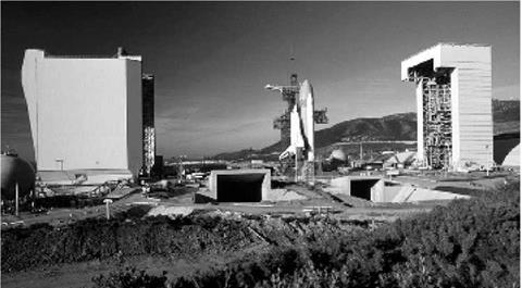
Zenit on the pad at Baykonur. Crew access tower is still in place (source: Russian Space Agency).

However, the project soon ran into substantial delays, mainly due to development problems with the RD-170/171 engines, highlighted by the explosion of a Zenit first stage at the test stand of NHkhimmash in June 1982. The switch to the single-chamber MD-185 engines considered for Energiya was also weighed for Zenit. Eventually, Zenit made its maiden flight on 13 April 1985, almost six years later than originally planned (see Chapter 6).

Original specifications for the 11K77 were to launch payloads into orbits with inclinations between 46° and 98° from both Baykonur and Plesetsk. The Zenit used highly automated launch facilities developed by the Design Bureau of Transport Machine Building (KBTM). These enabled several rockets to be placed on stand­by and be launched in quick succession. The idea was that the Zenit could swiftly replenish constellations of military satellites in case of an impending conflict or if some of them were knocked out by the enemy. Two launch pads were built at Baykonur. Construction of a Zenit pad at Plesetsk got underway in 1986, but the work was suspended in 1994 and the pad is being rebuilt for the Angara rocket family.

The vast majority of Zenit launches have carried KB Yuzhnoye’s Tselina-2 electronic intelligence satellites, placed into 850 km circular orbits inclined 71° to the equator. Actually, the Tselina-2 satellites are far underweight for Zenit, having been originally developed for launch by the lighter Tsiklon-3 rocket and then reoriented to Zenit because of slight increases in dimensions and mass. This was also the case for the Resurs-O1 and Meteor-3M satellites, originally built for launch by the Soyuz and Tsiklon-3 rockets. Most of the payloads really tailored for Zenit never flew as a result of the break-up of the Soviet Union in 1991, which not only led to a major economic crisis but also turned Zenit into a Ukrainian booster. Exceptions were two heavy photoreconnaissance satellites launched in 1994 and 2000 and the Okean-O ocean-monitoring satellite orbited in 1999.

From the outset Zenit was also developed as a man-rated launch vehicle with the necessary built-in redundancy and safety features. In the late 1980s NPO Energiya designed a Zenit-launched vehicle called Zarya (“Dawn”), which outwardly re­sembled an enlarged Soyuz descent capsule. A relic of those plans is a crew access tower still in place at the Baykonur Zenit pad. Zenit was also supposed to launch a variety of cargo ships and modules to Mir-2 and later to the International Space Station, but those plans were abandoned in 1996.

Compounding the problems for Zenit were three back-to-back launch failures that the rocket suffered in the 1990-1992 timeframe. The first of these resulted in the rocket crashing back seconds after lift-off, completely devastating one of the two Baykonur Zenit pads, which still lies in ruins today. But, while the end of the Cold War spelled bad news for Zenit as a domestic launch vehicle, it opened up new frontiers for its use in international programs. The first such opportunity arose in 1989, when Glavkosmos signed a deal to launch Zenits with Blok-DM upper stages from Cape York in Australia. Located on the east coast of Australia’s northernmost peninsula just 12 degrees south of the equator, Cape York was ideal for due east launches over the Pacific Ocean to place communications satellites into geostationary orbits.

Zenit-3SL lifts off from its ocean launch pad (source: Sea Launch).

A three-stage version of the 11K77 had already been envisaged for Soviet domes­tic missions by the original March 1976 government decree on Zenit. Although the Blok-DM had been considered from the outset, KB Yuzhnoye had preferred an upper stage with storable propellants (nitric acid and dimethyl hydrazine) plus an additional solid-fuel apogee kick motor, together capable of placing 1.3-ton payloads into geostationary orbit from Baykonur (compared with 1 ton for the Blok-DM). However, the use of the toxic storable propellants was considered unacceptable for launches from Australian territory, leaving Yuzhnoye no choice but to revert to NPO Energiya’s Blok-DM. Eventually, the Cape York plan fell through because of a lack of investor support.

The big break for the Zenit came in May 1995 with the official establishment of Sea Launch, a joint venture between KB Yuzhnoye, RKK Energiya, Boeing, and Kvaerner to launch three-stage Zenit rockets (Zenit-3SL) with Blok-DM upper stages on commercial satellite deployment missions from a converted Norwegian oil rig near the equator. Initial studies of sea-launched versions of Energiya, Energiya-M, and Zenit had been conducted at NPO Energiya in November 1991-December 1992 because of uncertainty over the future use of the Baykonur cosmodrome and rocket stage impact zones in independent Kazakhstan. Realizing that such a venture would require foreign investors, NPO Energiya officials pitched the idea of a sea-launched Zenit or Energiya-M to Boeing during a visit to the company’s Seattle headquarters in March 1993, with the final choice falling on Zenit in July 1993. Unknown to most of the parties involved (even Energiya), KB Yuzhnoye itself had studied sea-launched versions of Zenit together with KBTM in 1976-1980 under a research program known as Plavuchest (“Buoyancy’’). This would have seen the use of two catamaran-type vehicles, one acting as a launch pad and the other as a command center and storage facility for as many as five Zenit rockets with hypergolic upper stages. Many of the ideas worked out under Plavuchest were later incorporated into Sea Launch.

Sea Launch saw its inaugural mission on 27 March 1999 and has since averaged three launches per year, securing a solid place in the international commercial launch market. The company did suffer a significant setback on 31 January 2007, when one of its rockets exploded during lift-off. Although the launch platform escaped rela­tively unscathed, the commercial implications of this accident are as of yet unclear.

Significant differences between the heritage Zenit and the Sea Launch version were a new navigation system, a next-generation flight computer, and increased performance by mass reductions. The propulsion system remained essentially unchanged. Originally, the hope was to use an improved first-stage engine called RD-173 on which Energomash had begun work in the second half of the 1980s. This engine delivered 5 percent more thrust than the RD-171, had an improved turbo­pump assembly, and a modernized guidance and control system. Experimental versions of the engine underwent static test firings between 1990 and 1996, but further testing was suspended for financial reasons.

With the production line for the standard RD-171 closed due to a lack of state orders, Energomash had no other option but to modify existing RD-170 Energiya engines for use in the Sea Launch program. In 1996-1997 a total of fourteen RD-170 engines were “cannibalized” from mothballed Energiya strap-on boosters and shipped back to Energomash for modification. This batch was enough to ensure several years of Sea Launch operations, but eventually Energomash returned to its RD-173 plans. The modified engine, now redesignated RD-171M, has the same thrust as the RD-171, but is 200 kg lighter and has an improved guidance and control system. Testing started in 2004 and the engine made its debut in February 2006. In May 2004 Sea Launch also introduced a slightly improved RD-120 engine for the second stage (93 tons of thrust vs. 85 tons for the earlier version). Further perform­ance improvements may be achieved by adding suspended propellant tanks to the first stage.

In late 2003 the Sea Launch Board of Directors resolved to go forward with plans to offer launch services from Baykonur in Kazakhstan, in addition to its sea-based launches at the equator. An earlier attempt by Yuzhnoye to commercialize the two-stage Zenit from Baykonur had ended with an embarrassing launch failure in 1998 in which 12 Globalstar satellites came tumbling back to Earth minutes after lift­off. The new offering, Land Launch, is based on the collaboration of the Sea Launch Company and Space International Services (SIS) of Russia to meet the launch needs of commercial customers with medium-weight satellites. The Land Launch Zenits will have the same modifications as the Sea Launch version and can fly in a two-stage configuration for launches to low and elliptical orbits and with three stages to geostationary orbits [68].

RKK ENERGIYA’S KLIPER Original plans

For most of the 1990s the hard economic times forced RKK Energiya to limit manned spacecraft development to upgrading the existing Soyuz spacecraft. Work on a Soyuz successor didn’t resume in earnest until the turn of the century. By 2002 Energiya designers had settled on a lifting body borrowing technology from Soyuz and Buran. This was publicly announced as Kliper (“Clipper”) in February 2004 and described as a 12-14 ton spacecraft with a reusable return capsule. However, in November 2004 company officials revealed an alternative winged design for Kliper that was ultimately preferred over the lifting body.

In the 2004 plans Kliper had a reusable “Return Vehicle’’ (VA), made up of a crew cabin embedded in an unpressurized fuselage which could be either a lifting

Exploded view of Kliper: 1, fuselage shaped as lifting body; 2, winged fuselage; 3, crew cabin; 4, ABO body; 5, ABO Habitation Compartment; 6, launch vehicle adapter with emergency escape rockets (source: RKK Energiya).

body or a winged design. Attached to the aft of that was an expendable “Aggregate/ Habitation Compartment” (ABO), consisting of a Soyuz orbital module surrounded by a torus-shaped body. About half of the habitation compartment protruded from the aft of the body and had a docking port to link up with the ISS or other spacecraft.

The Return Vehicle’s blunt-shaped crew cabin offered 20 m3 of working space (five times as much as Soyuz) and could house a maximum crew of six (minimum crew of two). The independently developed fuselage would protect the front and lower part of the crew cabin during re-entry, descent, and touchdown. The fuselage and the upper part of the crew cabin had a heat shield consisting of 60 x 60 cm thermal covers made from the same material as Buran’s tiles. Also installed in the fuselage were LOX/ethanol attitude control thrusters and electricity-producing fuel cells derived from those developed for Buran.

The lifting-body configuration was probably inherited from so-called Recover­able Maneuverable Capsules (VMK) studied by Energiya in the early 1990s as return capsules for a series of vehicles intended for autonomous microgravity missions or space station servicing missions. The lifting-body fuselage was fitted with two rudders and two body flaps and would have a cross-range capability of up to 500 km (10 times more than Soyuz). Kliper would descend on parachutes, stowed in a container in the top section of the crew cabin, with pneumatic shock absorbers and small solid-fuel engines softening the touchdown.

For the winged version of the fuselage, RKK Energiya teamed up with the Sukhoy aviation design bureau, bypassing NPO Molniya, its former partner in the Buran program. The winged Kliper would make a classical horizontal runway landing using a conventional landing gear. This design would increase cross-range capability to 1,200 km and lower the deceleration forces for the crew during re-entry. Moreover, in the absence of parachutes, shock absorbers, and soft-landing engines, all of which are expendable systems, the degree of reusability would be higher.

The ABO’s Habitation Compartment performed the same functions as the Soyuz orbital module, providing 8 m3 of extra living space for the crew. Mounted on the aft end would be an active Soyuz-TM type docking port and a series of LOX/ethanol attitude control thrusters and maneuvering engines. The torus-shaped body sur­rounding the Habitation Compartment would among other things carry a thermal control radiator and propellant tanks for the aft engines and thrusters. The ABO would be jettisoned from the rest of Kliper after the deorbit burn and burn up on re-entry.

The launch vehicle originally considered for Kliper was Onega, a much upgraded Soyuz rocket with an increased propellant load and different engines that had evolved from two earlier proposals called Yamal and Avrora. Next, RKK Energiya set its sights on the already existing Zenit rocket, but the political problems stemming from the use of a Ukrainian launch vehicle eventually led Energiya back to upgraded Soyuz rockets, with Khrunichev’s Angara-A3 seen as a possible alternative. In the original Onega configuration Kliper had a launch escape tower mounted on its nose section, but in the later configurations this was replaced by eight solid-fuel rocket motors installed on an adapter between the launch vehicle and the spacecraft. As in

the earlier Zenit/OK-M and Energiya-M/OK-M2 plans, these motors could be used either in abort scenarios or to augment thrust in a nominal launch [16].

Mikoyan’s Spiral

Despite Dyna-Soar’s cancellation in December 1963, interest in spaceplanes did not abate. Although virtually all proposals adhered to the Dyna-Soar type boost-glide principle, the Soviet Air Force displayed increasing interest in the early 1960s in air – launched spaceplanes. Unlike the rocket-launched spaceplanes, these would not be

image29

Artyom Mikoyan.

tied to specific launch sites and could be launched from virtually any place in the world into a wide variety of orbital inclinations. This made the system less vulnerable to attack and gave it far more flexibility in fulfilling key military objectives such as timely reconnaissance of ground-based enemy targets and inspection and neutraliza­tion of enemy satellites. Air-launched systems were promoted at an Air Force conference at the Monino Air Force Academy in January 1962 [24]. Studies con­ducted in 1964-1965 by the Soviet Air Force research institute TsNII-30 also con­cluded that an air-launched vehicle would best meet the military requirements formulated for spaceplanes.

On 30 July 1965 the Ministry of the Aviation Industry (MAP) assigned the task of building such a system to the OKB-155 design bureau of Artyom Mikoyan. Renamed MMZ Zenit in 1966, the bureau was most renowned for its MiG fighter jets, but at the same time was no stranger to air-launched systems. Back in the 1950s Mikoyan had been involved in the development of the air-launched Kometa anti-ship cruise missile and in the early 1960s he had briefly worked on an air-to-space missile to be launched from a MiG-25 to destroy enemy missiles in flight [25]. In a newspaper article in January 1962, coinciding with the Air Force conference in Monino, Miko­yan had even publicly proclaimed the need for what he called a kosmolyot (a compound of kosmicheskiy samolyot, “spaceplane”) to provide the Soviet Air Force with an operational capability in space [26].

Mikoyan’s team wasted no time in getting down to business and by July 1966 had completed a preliminary design for the air-launched spaceplane system, called Spiral. Placed in charge of the project was 55-year-old Gleb Yevgenyevich Lozino-Lozins – kiy, a deputy of Mikoyan who had worked at the bureau since 1941 and had played a crucial role in the development of propulsion systems (especially afterburners) for numerous MiG jets. As a sign of his dedication to Spiral, Mikoyan set up a special space branch of his design bureau in the town of Dubna in April 1967. This was located on the same premises where Pavel Tsybin’s OKB-256 had worked on the PKA spaceplane a decade earlier. The chief of the branch was Pyotr A. Shuster and

Подпись: The Spiral system (source: www.buran.ru).

the head of its design bureau Yuriy D. Blokhin. Lozino-Lozinskiy’s deputy was Gennadiy P. Dementyev, the son of Minister of the Aviation Industry Pyotr Dementyev.

Spiral was a 115-ton system consisting of a Hypersonic Boost Aircraft (GSR or “Product 50-50’’), an Orbital Plane (OS), and a two-stage rocket to place the OS into orbit. The GSR, probably supposed to be built by the Tupolev bureau, was a 38 m long aircraft with a wingspan of 16.5 m and four air-breathing turbojet engines fixed under the main fuselage. An early version would burn kerosene and the final one hydrogen, with hydrogen gas being used to drive the turbine that in turn rotated the turbojet compressor. The two-stage rocket mounted on the back of the GSR was to be propelled by liquid oxygen/liquid hydrogen engines, but the designers ultimately wanted to replace the oxygen by fluorine. Although this is a highly toxic substance, it provided a higher specific impulse and would require smaller tanks than the LOX version. The hydrogen/fluorine engines were to be developed by Glushko’s Energomash design bureau, which by that time had already acquired extensive experience with testing fluorine-based engines.

When picking the shape of the spaceplane, Mikoyan’s engineers may at least partially have been inspired by flight tests of suborbital and atmospheric lifting bodies in the United States in the early 1960s, but in the end they came up with their own, unique design. The spaceplane proper was an 8 m long flat-bottomed lifting body with a large upturned nose and wings that could be rotated to vertical position during launch and the initial portion of re-entry. The vehicle’s aerodynamic design was such that thermal stresses during re-entry were minimized. The space­craft’s reusable heat shield was not solid, but was composed of a set of sheets, much like a fish’s scales. Suspended on ceramic bearings, these sheets could move relative to the vehicle’s body as the temperatures on various parts of the ships changed during re-entry. The plates were made of a niobium alloy with a molybdenum disilicide coating and could withstand temperatures up to about +1,500°C.

Situated in the front was the single pilot’s cockpit, which in case of an emergency could be ejected from the spaceplane and land by parachute. The headlight-shaped

image31

Spiral spaceplane in orbit (source: www. buran. ru).

capsule even had a small engine and a heat shield to deorbit and re-enter indepen­dently if an emergency arose in orbit. The power plant, located in the back, consisted of a single main engine for changing orbital inclination and deorbiting, two back-up deorbit engines, 16 attitude control thrusters, and a turbojet engine for subsonic propulsion and landing. The landing gear was made up of four skids mounted on the sides of the spaceplane.

In between the cockpit and the engine compartment was a 2 m3 payload section stowed full with reconnaissance equipment or weapons, depending on the mission. There were two reconnaissance versions of the spaceplane, one with optical cameras with a resolution of up to 1.2 m for detailed photography and another with an externally mounted radar antenna with a resolution of 20-30 m for spotting large objects such as aircraft carriers. An attack version of the OS was designed to destroy sea-based targets with a 1,700 kg nuclear-tipped space-to-surface missile, which required an additional 2m3 of volume in the mid-section of the spaceplane (at the expense of fuel).

Finally, there were two interceptor versions of the spaceplane. One was supposed to catch up with targets in orbit for close inspection and had six 25 kg homing missiles on board for destroying them (if necessary) from a maximum range of 30 km. The other was a long-range interceptor outfitted with 170 kg homing missiles to neutralize targets from a maximum distance of 350 km. Both interceptor versions had enough fuel on board to destroy two targets orbiting at altitudes of up to 1,000 km. The OS weighed 8.8 tons in all configurations, carrying 500 kg of payload for reconnaissance and interception missions, and 2,000 kg in its attack configuration.

A typical Spiral mission would begin with the GSR taking off at a speed of 380­400 km/h using a “launch truck”. Having accelerated the system to a hypersonic speed of Mach 6, the carrier aircraft would release the OS/booster combination at an altitude of 28-30 km and return to its home base. Subsequently, the two-stage rocket would place the spaceplane into a low orbit of approximately 130 x 150 km with inclinations varying between 45 and 135° (if launched from the territory of the USSR). If equipped with a main engine burning liquid fluorine (F2) and amidol (50% N204, 50% BH3N2H4), the reconnaissance and interception versions could change their inclination by 17° for a second target run and the attack version by 7-8°. The interception version could also simultaneously change inclination by 12° and ascend to an altitude of up to 1,000 km.

After a mission of maximum three orbits, the spaceplane would fire its deorbit engine and dive into the atmosphere at a 45-60° angle of attack with the wings folded to near-vertical position, allowing the air stream to flow from the body down to the wings, rather than to the wing leading edges. Cross-range capability was between 1,100 and 1,500 km, offering the pilot much flexibility in choosing landing sites. After unfolding the wings to a near-horizontal position and igniting the turbojet engine, the pilot would land the spaceplane on a dirt runway at a speed of no more than 250 km/h.

According to plans formulated in the preliminary design in 1966 the Spiral program was to be conducted in four stages. The first step was to build three suborbital prototypes and launch them from the back of a Tu-95KM aircraft, the same type of plane Tupolev had intended to use for his own spaceplane tests. Subsonic flights were to begin in 1967, followed by X-15 type supersonic and hypersonic flights in 1968 to altitudes of 120 km and speeds of Mach 6-8. In the second stage Soyuz rockets would be used to launch full-scale versions of the 0S (“EPOS”) into orbit on both unmanned and manned missions in 1969 and 1970, with one of the mission objectives being to perform an 8° plane-changing burn. Stage 3 would see test flights of a kerosene-fueled version of the GSR in 1970, with the hydrogen-fueled version being introduced in 1972. That same year the fourth stage was to begin with an all-up test of the Spiral complex using a kerosene-fueled GSR and a LOX/liquid hydrogen rocket booster. In 1973 the hydrogen-fueled GSR would be used for a manned test of the Spiral system. Later steps were the introduction of fluorine-based engines for both the rocket and the spaceplane and the replacement of the expendable rocket by a reusable rocket with hypersonic scramjet engines burning liquid hydrogen.

Spiral was by far the largest-scale Soviet spaceplane program of the 1960s, although the amount of money invested in it must still have been dwarfed by what the US Air Force spent on Dyna-Soar. It was also the first for which cosmonauts began training. A Spiral training group was set up at Star City in 1966 and existed until 1973. The Air Force cosmonauts known to have been involved in Spiral at one time or another are Gherman Titov, Anatoliy Kuklin, Vasiliy Lazarev, Anatoliy Filipchenko, Leonid Kizim, Anatoliy Berezovoy, Vladimir Dzhanibekov, Vladimir Kozelskiy, Vladimir Lyakhov, Yuriy Malyshev, Aleksandr Petrushenko, and Yuriy Romanenko. The training mainly involved flying a variety of aircraft from an Air Force test site in Akhtubinsk (Volgograd region) to acquire the status of test pilot.

By the end of the 1960s the Spiral project had still not been officially sanctioned by a party/government decree. One man who tried to change that situation was

Nikolay Kamanin, the Air Force Commander-in-chief’s Aide for Space Matters, who had been pushing for spaceplanes since the early 1960s, seeing them as a logical extension of military aircraft. Sometime in late 1969 Kamanin and his entourage worked out a draft for such a decree to be sent to the Council of Ministers and the Central Committee. The draft was supposed to be signed by seven ministers and high – ranking military officials, but, as Kamanin recounts in his diaries, by April 1970 only four had done so. The delay was caused at least partly by a conflict that had arisen over the missions of future spaceplanes between Sergey Afanasyev, who headed the Ministry of General Machine Building (MOM, the “space and missile ministry’’), and Minister of the Aviation Industry Pyotr Dementyev. Afanasyev had signed the draft with the remark that besides military spaceplanes there should also be winged space­craft adapted as transportation systems. Subsequently, Dementyev refused to put his signature under it, fearing that the organizations under his ministry would become overloaded with space-related work, which was not their primary line of business.

In the middle of 1970 Defense Minister Andrey Grechko sent a letter to Central Committee Secretary for Defense Matters Dmitriy Ustinov, in which he justified the need to build spaceplanes and asked him to order several ministries to reach a consensus on a draft government decree on Spiral. Three months later that was apparently achieved, but by that time Grechko, who was not at all space-minded, seems to have had a change of heart on the issue. When the moment came for him to sign the draft himself, he vetoed it, writing on the document in question that Spiral was “a fantasy’’ and that money should be spent on more realistic things. Grechko’s rejection of the draft sounded the death knell for Spiral. Kamanin asked Air Force Commander-in-Chief Pavel S. Kutakhov (assigned to the post in March 1969) to try and change Grechko’s mind, but Kutakhov himself seems to have shown little enthusiasm for the project [27]. To make matters even worse, Mikoyan, backing the program with his authority, died in December 1970, and Lozino-Lozinskiy was forced to divert his attention from space matters after having been assigned chief designer of the new MiG-31 interceptor in 1971.

All this meant that by the turn of the decade the prospects for Spiral were very bleak indeed. Aside from interdepartmental squabbling and budgetary issues, other reasons for the lukewarm interest in Spiral may have been the challenges involved in mastering advanced technologies such as the hypersonic carrier aircraft and the reusable heat shield. In addition to that, it was probably realized by now that at least some of the missions planned for Spiral could just as well be performed by unmanned satellites.

Remarkably enough, the program continued on what appears to have been a semi-legal basis and eventually did see some hardware make it off the ground, even after the Buran program was approved in 1976. Why Spiral wasn’t canceled outright is a fact that remains to be satisfactorily explained. In the mid-1970s designers looked at enlarged versions of the Spiral spaceplane to be launched by the Proton rocket or the massive Energiya booster (see Chapter 2), but these appear to have been short­lived paper studies not enough to justify the continuation of a test flight program.

Recent evidence indicates MAP may eventually have seen Spiral as no more than a trump card in a seemingly mundane tug-of-war with MOM over subordinate organizations. One source of acrimony between the two ministries was that many factories and research institutes of MAP had been transferred to MOM after the latter’s establishment in 1965. Around the mid-1970s Lozino-Lozinskiy and MAP deputy minister Aleksey Minayev reportedly convinced MAP minister Dementyev that by demonstrating its ability to fly Spiral hardware, MAP would eventually muster the political support required to have some of those organizations transferred back to its ranks. Another factor enabling the continuation of Spiral may have been the death in April 1976 of Defense Minister Grechko, one of the program’s most vigorous opponents [28].

Whatever the real motives for keeping Spiral alive, several test flights were conducted in support of the program between 1969 and 1978. The Gromov Flight Research Institute (LII) built several scale models of the spaceplane known as BOR-1, 2 and 3 (“Unmanned Orbital Rocket Plane’’). These were launched on suborbital trajectories by R-12 missiles from Kapustin Yar between 1969 and 1974. A full-scale prototype for subsonic flights (105.11, nicknamed “Lapot” or “Bast Shoe’’ and sometimes also called EPOS, like the orbital test bed) was ready for test flights by the mid-1970s. Staged from the Air Force site in Akhtubinsk, they began in December 1975 with a series of taxi runs and brief flights (first in June 1976) in which the plane took off on its own power. At the helm for those tests were civilian test pilots Aviard Fastovets, Valeriy Menitskiy, Vasiliy Uryadov, Igor Volk, and Aleksandr Fedotov. After a number of “captive-carry’’ tests, the 105.11, piloted by Fastovets, was dropped from the belly of a Tu-95K from an altitude of 5 km for the

image32

The 105.11 atmospheric test bed (B. Hendrickx).

first time in October 1977. Five more drop tests followed the following months, three performed by Fastovets, one by Pyotr Ostapenko, and one by Uryadov. The final one in September 1978 ended with the plane making a hard landing to the right of the runway, causing some damage to the landing gear. The 105.11 was never refurbished for another flight. It can still be seen today at the Monino Air Force museum outside Moscow. A model for supersonic tests (105.12) was built but never flown and a model for hypersonic tests (105.13) was partially built.

Apparently, Spiral died a silent death in the late 1970s as work on Buran got underway in earnest. It did have at least one important legacy for the Buran program. A subscale model (BOR-4) originally intended for orbital test flights of the Spiral spaceplane was eventually launched on single-orbit missions in 1982-1984 to test materials for Buran’s thermal protection system (see Chapter 6). The work on Spiral also served as the basis for studies of new air-launched spaceplanes in the 1980s and 1990s, particularly the MAKS project (see Chapter 9) [29].

The MTKVP lifting body

Called the Reusable Vertical Landing Transport Ship (MTKVP), the lifting body was a 34 m long vehicle consisting of three main sections: a front section with the crew cabin, a mid-section containing a huge payload bay, and an aft section with orbital maneuvering engines. After using its limited aerodynamic characteristics during the hypersonic stage of re-entry, the vehicle would deploy a series of parachutes at an

image45

The MTKVP lifting body (source: www. buran. ru).

image46

The MTKVP sitting atop the RLA-130V launch vehicle (source: www. buran. ru).

altitude of 12 km and a speed of 250 m/s. Vertical landing speed would be dampened with small soft-landing engines and horizontal speed with a ski landing gear.

One of the big advantages of this design was that the ship did not need expensive runways, although some of the plans did envisage landing on a prepared dirt surface. The absence of wings, which are dead weight for most of the flight anyway, also saved a lot of mass. The MTKVP would weigh 88 tons and have a payload capacity of 30 tons to a low 50.7° inclination orbit and a return capacity of 20 tons. Moreover, the MTKVP could rely on proven technologies such as other aerodynamically shaped objects (in particular, the Soyuz descent capsule and nuclear warheads) and parachute and soft-landing systems that had been used for some years by airborne troops to safely land heavy cargos. The idea also was to retrieve the RLA strap-on boosters in a similar fashion, leading to additional cost savings.

However, a major disadvantage of the MTKVP was its low cross-range cap­ability. This was particularly important for the Russian orbiter, because unlike its American counterpart, it could land only on Soviet territory. At a later stage in the design process an attempt was made to improve the vehicle’s cross-range capability from about 800 km to 1,800 km by giving the fuselage a slightly triangular shape. Another problem was that a vehicle of this type would be exposed to extremely high temperatures (about 1,900°C), placing high demands on the heat shield and requiring long turnaround times for repair work. Many doubted if it would be reusable at all. Moreover, since the vehicle was supposed to land in the steppes, it would have been a cumbersome process to recover it and transport it back to the launch site.

The launch vehicle for the MTKVP was known as RLA-130V. It consisted of a 37.4m high core stage powered by two 250-ton thrust LOX/LH2 RD-0120 engines and six 25.7 m high strap-on rockets with 600-ton LOX/kerosene RD-123 engines [54].

THE BURAN AIRFRAME

Buran was a double-delta winged spacecraft capable of putting people and cargo into low Earth orbits and returning them to a controlled gliding landing. Aerodynamic­ally, it was a near-copy of the US Space Shuttle Orbiter. The Soviet orbiter was 36.37m long and had a maximum diameter of 5.50 m. Buran’s airframe consisted of the crew module shell, the forward fuselage, the mid fuselage, the aft fuselage, a body flap, delta wings with elevons, and a vertical tail. The airframe was largely made of aluminum alloys such as D16 (also widely used in aircraft) and 1201 (specifically developed for Buran), designed to withstand temperatures between about — 130°C and +150° C. Other materials used were various titanium alloys for areas experiencing higher stresses as well as a variety of high-temperature and tensile steels. Playing a key role in the development of these materials was the All-Union Institute of Aviation Materials (VIAM). All elements of the airframe were covered by reusable thermal insulation to protect the structure against the wide range of temperatures experienced during ascent, in orbit, and during re-entry.

The forward fuselage (Russian acronym NChF) was 9 m long, 5.5 m wide, and 6 m high. It housed the pressurized crew module and forward reaction control system thrusters. Structurally, it consisted of the nosecap, the forward thruster module, and an upper and lower section. The latter two were manufactured separately to allow the pressurized crew module to be inserted during final assembly.

The mid fuselage (SChF) was 18.5 m long, 6 m wide and 5.5 m high and contained the payload bay, the nose landing gear, the electricity-generating fuel cells, and their fuel tanks, wiring for the power system and flight control system, various tanks for the environmental control system and thermal control system, and also propellant lines connecting the forward and aft thruster sections. Twenty-six frame assemblies provided stabilization of the mid fuselage structure. Longerons on either side absorbed the bending loads of the vehicle and contained the hinges of the payload bay doors. Mounted in the side walls were several doors to vent the vehicle’s unpressurized compartments and to service the fuel cells. The front part of the mid fuselage housed the nose gear wheel well, nose landing gear, and nose gear

The Buran airframe 105

Mam elements of Buran’s airframe: 1, nosecap; 2, forward fuselage; 3, forward thrusters; 4, crew module; 5, wing; 6, reinforced carbon-carbon panels; 7, elevons; 8, elevon hinges; 9, mid fuselage; 10, tail; 11, rudder/speed brake; 12, aft fuselage; 13, body flap; 14, payload bay doors with radiators; 15, main landing gear door; 16, main landing gear; 17, nose gear door; 18, nose gear; 19, entry hatch (source: Yuriy Semyonov/Mashinostroyeniye).

doors. The nose gear was situated farther to the back than the Orbiter’s, where it is part of the forward fuselage.

The payload bay doors consisted of port and starboard doors hinged at each side of the mid fuselage. They were 18.5m long and had a gross area of 144 m2. Each door was made up of four segments, each of them resting on 12 hinges. The doors were held closed by a total of 33 latches, consisting of 16 bulkhead latches (eight forward and eight aft) and 17 payload bay door centerline latches. The doors were composed of a lightweight graphite-epoxy composite material (KMU-4E) that was much lighter than the D-16 aluminum alloy used in most of Buran’s airframe. At a later stage it was supposed to have been replaced by an even lighter material called KMU-8. The total mass of Buran’s doors was 1,625 kg, which was 620 kg lighter than the mock-up aluminum doors built for the BTS-002 vehicle that flew the atmospheric approach and landing tests. The doors also served as a strongback for the radiator panels that allowed heat rejection in orbit.

The aft fuselage (KhChF) was 3.6 m long, 5.5 m wide, and 6 m high. It housed the Combined Engine Installation with its orbital maneuvering engines and steering

thrusters, the Auxiliary Power Units, the hydraulic system, and a pressurized equip­ment bay. On the outside were attach points for the tail, the body flap, the wings, and the brake chute.

Buran’s double-delta wings provided aerodynamic lift and control of the vehicle during atmospheric flight. The vehicle’s lift-to-drag ratio was 1.3 during the hyper­sonic phase of re-entry and 5.6 at subsonic speeds. Wingspan was 23.92 m and total area 250 m2 (virtually identical to the values for the Space Shuttle Orbiter). The wings had a 45° degree sweep on the inner leading edge and a 79° sweep on the outer (vs. 45° and 81° on the Shuttle Orbiter). The wings were positioned slightly more forward on the fuselage than those of the Space Shuttle, helping to adjust the vehicle’s center of gravity in the absence of heavy, aft-mounted main engines.

Elevons provided pitch and roll control during atmospheric flight. They were divided into two segments for each wing, with each segment being supported by three hinges. Pitch control was achieved by deflecting all elevons in the same direction (elevator function) and roll control by deflecting the left-wing and right-wing elevons in opposite directions (aileron function). Each elevon traveled 35 degrees up and 20 degrees down (compared with 40° and 25° for the Space Shuttle Orbiter).

The tail (or “vertical stabilizer’’) consisted of a structural fin surface and a two-part rudder/speed brake. Its total area was 39 m2 and that of the rudder/speed brake 10.5 m2. As on a conventional airplane, the rudder provided yaw control when both panels were deflected left or right, but by splitting each of its two panels into two halves it also acted as a speed brake, a feature unique to rapidly descending gliders such as Buran and the Shuttle. The segments could be deflected in the same direction for rudder control of plus or minus 23° (27° on the Orbiter) and the halves could be moved in opposite directions for speed brake control for a maximum of about 43.5° each (49.3° on the Orbiter).

An aerodynamic surface not seen on conventional airplanes is the body flap, attached to the bottom rear of the aft fuselage. With a maximum deflection angle of 30°, it provided pitch control trim to reduce elevon deflections [10].

Thrusters and verniers

Buran had 38 primary thrusters (“Control Engines’’ or UD) (exactly the same number as on the Space Shuttle Orbiter) and eight verniers (“Orientation Engines’’ or DO) (two more than on the Orbiter). Together the primary thrusters and verniers formed the Reaction Control System (RSU). The primary thrusters provided both attitude control and three-axis translation, and the verniers only attitude control. They were used for these functions during the launch, separation from the core stage, on-orbit, and re-entry phases of the flight (up to an altitude of 10 km). If needed, some of the UD thrusters could also act as a back-up for the DOM engines.

Orbital maneuvering engines (B. Vis).

The UD thrusters (17D15), built in-house at NPO Energiya, had a thrust of 390 kg and a specific impulse between 275 and 295 s. Unlike the DOM engines, they used gaseous rather than liquid oxygen as an oxidizer. This was obtained with a small turbopump assembly mounted on the ODU LOX tank. First, liquid oxygen from the LOX tank passed through the pump, where its pressure was increased to 78.4 MPa. Then it entered a gas generator where it was ignited with a minute amount of sintin fuel (ratio of 100: 1) to form a mix of gaseous oxygen, carbon dioxide, water vapor, and droplets with a temperature of 60°C. After any residual liquids had been dumped

Aft thrusters (B. Vis).

overboard, the gaseous oxygen was used to drive the turbine and was then stored in separate tanks at pressures ranging from 2.45 to 4.9 MPa. From there it was delivered to the combustion chamber to react with liquid sintin through electrical ignition. Each UD thruster could be fired for a duration of anywhere between 0.06 and 1,200 seconds and be ignited up to 2,000 times during a single mission. The thrusters were designed to sustain 26,000 starts and 3 hours of cumulative firing.

The DO verniers (17D16 or RDMT-200K) provided 20 kg of thrust and had a specific impulse of 265 s. They were developed by the Scientific Research Institute of

Machine Building (Nil Mashinostroyeniya) in Nizhnyaya Saida, which had been a branch of the Scientific Research institute of Thermal Processes (Nil TP) until 1981 and specialized in small thrusters for spacecraft. The RDMT-200K was probably a cryogenic version of the RDMT-200, a thruster with similar capabilities built for the Almaz space station but burning storable propellants. The verniers were similar in design and operation to the UD thrusters, but used liquid oxygen and a different cooling system. They were intended for short-duration burns with an impulse time between 0.06 and 0.12 seconds and could be ignited up to 5,000 times during a single mission. Thrusters based on the RDMT-200K were supposed to fly on the upper stage of the Yedinstvo/ULV-22 rocket, a launch vehicle studied by the Makeyev bureau in the late 1990s to fly from Australian territory.

Aside from the ODU engines and thrusters, Buran had four small solid-fuel motors (thrust 2.85 tons each) to instantly separate the vehicle from the Energiya core stage in case of a multiple engine or other catastrophic launch vehicle failure. Presumably developed by NPO iskra, they were situated in the nose section of the vehicle and should have given Buran enough speed to stay clear of the out-of-control rocket after separation. They were not supposed to be used in a standard separation from the core stage after main engine cutoff. The solid-fuel motors were apparently not installed on the first flight vehicle that made the one and only Buran mission in 1988.