Campaign objectives:
The contrast between the Soviet space program in the mid-1970s and the mid-1980s was stark. In the mid-1970s the Soviets were in the deep shadow of the Americans. They had convincingly lost the race to land a man on the Moon. The Mars lleets of 1971 and 1973 were failures, whereas the Mariner 9 and Viking missions were total successes. In the 1970s the Americans launched inward lo Mercury and outward to Jupiter, Saturn, Uranus, and Neptune. The Soviets were confined Lo Venus. But in just 10 years all this was turned on its head. By the mid-1980s the US launch rate lor planetary missions had fallen to zero and their ambitious plans for Venus, Mars and Jupiter orbiters were troubled with delays and funding problems. By failing to fund a spacecraft for the Halley armada, the US had yielded the leadership it had worked so hard to achieve to Europe and Russia.
While the American program was struggling in the 1980s, the Soviet program was flourishing. Since 1975 they had achieved a string of unbroken successes at Venus with ever more complex spacecraft. They had taken the international lead from the US by opening the Vega missions to international participation on an unprecedented scale. Their Proton-launched spacecraft could carry a large, comprehensive payload of sophisticated and complex instruments. With landers and balloons at Venus and a gravity-assist to Halley the Vega mission had demonstrated boldness, ambition and success on a grand scale that silenced Western criticism of the quality of the Soviet program. The USSR was launching a space station. Mir, launching the largest rocket ever built, Energiya, developing a competitor to the US Space Shuttle, Buran, and launching almost 100 spacecraft per year. The National Geographic magazine gave a profile on the massive Soviet space industry and its successes, and Time magazine ran a cover story ‘Surging ahead Soviets overtake the US as the No. l spacefaring nation’. By the mid-1980s, therefore, Soviet confidence and optimism were running high.
After the Vega missions there was a consensus that the Venera series had run its course, having accomplished about all that it could. Of course there were ideas for long – lived landers and aerostats, but these were for the future. As the Vega missions were underway, the ‘Martians’ at IK I were insistent that it was now time to revive interest in Mars. The early proposals for a Mars sample return mission had fallen by the wayside, with even the plan designed to use the Proton launeher being discarded in 1977. Since then, however, the ‘Martians’ had been investigating more practical missions and had revived interest in a proposal to investigate Phobos. the larger of the planet’s two small moons. Strategic planning at IK I was still to seek to outdo the Americans, and since the US had not considered Phobos as a target there was scope for another Soviet showplace. They would not be repeating or competing with the US. After the Viking landers did not find any strong evidence for life on the surface of Mars the Americans had all but abandoned the planet. In addition, the continuing development of the Mars 2 to 7. Venera 9 to 16. and Vega 1 and 2 lines of heavy Proton-launched spacecraft provided the technology to undertake very capable Mars missions on a scale that the US was no longer able to fund. The lack of immediately compelling Venus missions, the lack of US interest in Mars, and the availability of proven technology, were compelling reasons to mount another campaign at Mars. So Soviet engineers decided to develop a new-gcncraiion planetary spacecraft based on the Venera-Vega heritage and to switch their attention from Venus to Mars. It was expected that the new spacecraft would serve as the baseline for the next 20 years of Soviet planetary exploration. The three Vega spacecraft spares were refurbished for astronomy missions in Earth orbit, two of which flew as Astron in 1983 and Granat in 1989.
|
Spacecraft launched
|
|
|
First spacecraft:
|
Phobos 1 (IF No. 101)
|
|
Mission Type:
|
Mars Orbitcr. Phobos Flyby/Landers
|
|
Country’; Builder:
|
USSR NPO-Lavochkin
|
|
Launch Vehicle:
|
Proton-K
|
|
Launch Date; Time:
|
July 7, 1988 at 17:38:04 UT (Baikonur)
|
|
Mission End:
|
September 2, 1988
|
|
Outcome:
|
Failed in transit due to command error.
|
|
Second spacecraft:
|
Phobos 2 (IF No. 102)
|
|
Mission Type:
|
Mars Orbiter, Phobos Flyby/Landers
|
|
Country/Builder:
|
USSR, NPO-Lavochkin ”
|
|
Launch Vehicle:
|
Proton-K
|
|
Launch Date: Time:
|
July 12, 1988 at 17:01:43 UT (Baikonur)
|
|
Encounter Date/ Time:
|
January 29, 1989
|
|
Mission End:
|
March 27, 1989
|
|
Outcome:
|
Lost in Mars orbit prior to Phobos encounter.
|
The concept of a mission to Phobos actually preceded the Vega missions, but the latter had priority because their launches were dictated by the apparition of Comet Halley. The intention to send spacecraft to Phobos was first announced in November 1984, a month before the launch of the Vega missions. At that time the schedule was to launch in 1986. but this was slipped to 1988. Several mission scenarios had been considered including a Phobos landing, an outpost on Phobos for remote sensing of Mars, and a Phobos landing with sample return. The mission design selected was no less audacious, but less risky to arrange. The plan was to hover a large spacecraft about 50 meters above Phobos and conduct both passive and active remote sensing using lasers and particle guns. Later the mission expanded to include deploying two small landers for Phobos, one built by IKI and the other by the Vernadsky Institute. This campaign was to be the first in a Mars-focused exploration program which the Soviets expected to be every bit as successful as their exploration of Venus.
The objectives of the Phobos missions were to:
1. Conduct studies of the interplanetary environment
2. Perform observations of the Sun
3. Characterize the plasma environment in the Martian vicinity
4. Conduct surface and atmospheric studies of Mars
5. Study the surface composition and environment of the moon Phobos.
Having reaped major scientific and political results by the internationalization of the Vega missions, this policy was repeated for the Phobos campaign. This time the involvement of the US and Western countries was even more extensive. Many of the investigations and instruments were supplied by European countries; not only Soviet Bloc but also Western Europe. Given its history of cooperation in Soviet missions starting with the 1971 Mars missions. France was the primary Western contributor. The fact that the IJS supplied one instrument, a number of science co-investigators, and tracking support, was a major breakthrough initiated by the Soviet Union as the Cold War thawed. As a result, each spacecraft had a record number of instruments with which to perform a comprehensive scientific investigation of Mars and Phobos. In fact, each spacecraft carried twenty-four experiments provided by the USSR, the European Space Agency, and thirteen other countries including the IJS. The Phobos missions constituted an aggressive, innovative, and very impressive scientific attack on both Mars and Phobos, especially when compared to the modest orbiter that the IJS was then planning to send to Mars in 1990.
Spacecraft:
Orbiter:
The spacecraft was similar to the Vega design but represented a new generation in technology, and was the first major design change in Soviet planetary missions since Mars 2 and 3. It was the heaviest planetary spacecraft yet devised, with a total mass over 6,200 kg including 3,600 kg for the separable ADU propulsion system. The scientific payload capacity was an incredible 500 kg. It was constructed around a pressurized toroidal compartment for electronics, with four spherical outrigger tanks containing hydrazine monopropellant for the onboard propulsion system. The solar panels were mounted with their flat planes parallel to the toroid, perpendicular to the earlier Mars and Venus spacecraft. Attached to the outrigger tanks were twenty-four
|
|
|
Cyftndncal instrument module
|
|
|
Toroidal instrument module
|
|
|
|
|
|
|
МоЫг Under Stationary Under
|
|
|
|
|
|
|
Autonomous Propulsion System
|
|
|
Figure 19.1 Phobos spacecraft (courtesy NPO-Lavochkin).
|
|
|
Instrument Electronics Boxes
|
|
|
|
|
|
|
|
|
|
|
Figure 19.2 Phobos spacecraft and instruments, after the ADU propulsion system has been jettisoned (courtesy NPO-Lavochkin).
|
|
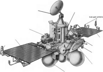
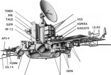
engines rated at 50 N of thrust and four engines rated at 10 N for maneuvering, and a do/cn thrusters rated at 0.5 N for attitude control; and there were additional thrusters on the body and the solar panels. Two basic attitude control modes were provided: 3- axis control, and ‘drift mode’ control with the solar panels facing the Sun and the vehicle spin stabilized. The attitude control avionics consisted of Sun sensors, star sensors, gyroscope and accelerometer platforms, and a triply-redundant computer.
f or the Phobos mission this basic spacecraft had a cylindrical pressurized module mounted above the toroid. This module contained spacecraft control avionics, radio systems, and science experiments. It had a 2-axis 1.65 meter diameter parabolic high gain antenna on top. A 30 megabit data recorder was provided as a buffer. With the upgraded ground systems, the new 50 W transmitter was capable of 65 to 131 kbits/s from Mars. The old Venera control system was abandoned and a new dual-processor computer that incorporated a 4.8 gigabyte memory developed jointly with Hungary was to perform the complex maneuvers to match orbits with the target moon and make the flyby during which the spacecraft would undertake its closest observations and release its landers. Payload modules were mounted both inside and outside the cylinder. Unlike Vega, there was no scan platform; to make planetary observations the spacecraft had to be reoriented away from Earth-pointing. While cruising it would employ the drift mode in which it spun slowly with its solar panels pointed at the Sun.
Another innovation was the Autonomous Propulsion System (ADU) for the final escape burn, midcourse corrections, and orbit insertion. It was to be discarded after completing the major orbital maneuvers. This large assembly was carried below the toroidal section. It comprised eight tanks, four 1.02 meters in diameter and four 0.73 meters in diameter, nested around a single К I DIJ-425A restartable engine that could be throttled between 9.8 and 18.6 kN, burning UDMH and nitrogen tetroxide. It had a total burn time of 560 seconds. The ADU weighed 600 kg dry and was capable of carrying 3,000 kg of propellants. It w^as an extensive redesign of the main propulsion stage of the old Ye-8 lunar spacecraft. Part of the strategy was that the ADU would serve as a fifth stage of the launcher to achieve the desired interplanetary trajectory, and then perform the most energy intensive maneuvers at the target planet. It would eventually become the ‘Fregaf stage and be extensively used to augment the Soyuz launcher.
The Phobos mission strategy was to place the spacecraft into an initial elliptical near-equatorial orbit that maneuvers over several weeks would eireularize very close to that of Phobos. The ADU w ould be jettisoned, and from this intermediate orbit the moon would be approached several times at low velocity over a period of w eeks at distances varying from several hundred kilometers to 35 km. Observations of the moon would be used to refine knowledge of its orbital parameters sufficiently for a maneuver to be calculated which the onboard propulsion system would perform to produce the desired close flyby. The radar would be activated at a range of 2 km and the spacecraft w ould be controlled using the radar to perform a 20 minute pass at an altitude of about 50 meters at a relative velocity of 2 to 5 m/s. Considering the large topographic variation, this low’ altitude flyby would need a very robust and complex automated control system. Two types of lander w ere to be deployed, one of which
would be stationary and the other capable of‘hopping’ around in the weak gravity. Two active remote sensing experiments would be attempted using laser and ion guns in a manner that would enable the spacecraft to fly through the material evaporated off the surface for analysis with mass spectrometers. An active radar system would map the regolith material down to 2 meters depth. Passive remote sensing included both imaging and spectrometry. After the low pass over Phobos, the spacecraft was to adjust its orbit and spend its remaining time observing Mars. If the Phobos flyby were a success, there was the possibility of maneuvering the spacecraft to make a similar flyby of Dcinios.
 Launch mass:
AD U propulsion system (Arbiter wet mass:
Instrument payload:
Mobile lander:
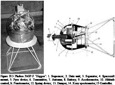
The PrOP-F hopper (‘Frog’) resembled a small, flattened ball consisting of a 50 cm diameter hemisphere on top of a semi-cylindrical base. It would be ejected from the side of the spacecraft at the time of closest approach, and fall to the surface in the moon’s weak gravity – some 2,000 times weaker than that of Earth. It was designed
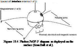
to survive contact at a horizontal speed of.3 m/s and a vertical speed of 0.45 m/s. A damper truss would reduce the time taken to settle on the surface after initial impact. This would be ejected after settling, and a set of four long levers (‘whiskers’) on the base, two of which could be rotated, would deploy in order to orient the ball flat-side down. After about 20 minutes of sensing and the transmission of results, the hopper would flex its levers to propel itself to another location about 20 meters away. Each such hop would peak at a height of about 20 meters. The levers would right the ball after each landing. Ten hops were planned. The hopper was powered by a 20 amp – hour battery, and a 0.3 W transmitter would send to the spacecraft at 224 bits/s. Operations would begin immediately upon landing, and run for the 4 hour battery lifetime, by which time the spacecraft would have traveled about 300 km from the moon. Due to mass limitations the hopper was assigned only to Phobos 2.
Mobile lander mass: 50 kg
Payload: 7 kg
Stationary lander (DAS):
The stationary lander was carried on top of the spacecraft and was to be deployed at 2.2 m/s by a pair of arms. Once free, it would use cold gas thrusters to spin itself for stability at about 2 radians per second and also to propel itself towards the surface. It was designed to survive contact at a vertical speed of 4 m/s and a horizontal speed of at most 2 m/s. Contact probes underneath the lander were to ignite hold-down solid rockets, and simultaneously fire a harpoon on the underside down into the surface. The harpoon was tethered and nesting motors would wind up the tension to hold the lander firmly in place on the surface. After allowing the dust to settle for 10 minutes, the lander would extend three legs to raise its instrument platform 80 cm above the surface while maintaining the tension in the harpoon tether, and deploy and point its solar panels and antenna. Because Phobos rotates relative to the Sun, the orientation of the solar panels would be controlled by Sun sensors.
The lander was to undertake science investigations for 3 months, communicating directly with Earth by a transmitter and receiver at 1,672 MHz using antennas on the
|
Antenna
Solar panel (1 of 3)
|
|
|
|
|
|
|
—– Contact probe (1 of 3)
|
|
|
ALPHA-X X-ray fluorescence ——
spectrometer
|
|
|
___ ALPHA-X alpha-proton
spectrometer
|
|
|
Figure 19.5 Phobos DAS stationary lander diagram as deployed on the surface (from Ball et пі.).
|
|
|
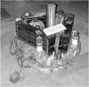
Figure 19.6 DAS stationary lander folded for attachment to the Phobos spacecraft (courtesy NrO-Lavochkin).
|
|
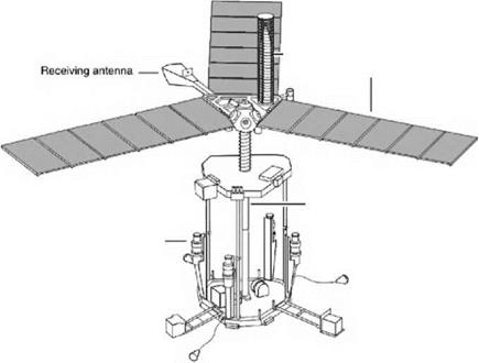
instrument platform. It was realized that there might be shadowing problems on the solar panels, but there was insufficient time to develop mitigation options even using a secondary battery. Also, the Soviets and French developed different algorithms for data compression and because of insufficient capacity in the computer to implement both, the landers on the two spacecraft had different algorithms. The dual-processor computer was supplied by Hungary under the supervision of IKI. At a data rate that varied from 4 to 16 bits/s. three or four communication sessions would be needed to transmit a single image frame.
Stationary lander mass: 67 kg
Payload: 20.6 kg
The number of science instruments and the complexity of the spacecraft and its operations was unprecedented. A special MORION central interface was provided to handle the complexities. In the end, the mass budget was exceeded and some of the instruments had to be deleted from each spacecraft. The PrOP-F hopper was deleted from Phobos 1, as were the TERMOSKAN and ISM infrared instruments. Phobos 2 lost the RLK radar, the TEREK solar telescope, and the 1PNM neutron detector. The complexity of the mission was daunting, both to develop with all of its international interfaces and to operate with all of its instruments competing for operational time including spacecraft targeting and data transmission.
Payload:
Ovhiter:
Phobos active remote sensing:
1. Laser mass spectrometer for elemental surface composition (LIMA-D. USSR-Bulgaria-Finland-FRC-DDR-Czechoslovakia)
2. Ion gun mass spectrometer for elemental surface composition (DION, USSR-Austria-Finland-France)
3. Radar system for subsurface structure and mapping (RLK, USSR), Phobos 1 only
The 80 kg laser mass spectrometer was to conduct active remote sensing. It would lire 150 laser pulses, each of 10 nanoseconds, to evaporate material in the uppermost 1 mm of the surface of Phobos. The mass spectrometer would analyze the ions in the resulting plasma cloud to provide an elemental analysis for ranges up to 100 meters. The 24 kg ion gun mass spectrometer was to lire krypton ions at the moon and then measure the ions scattered back from its surface. Between them the two instruments were to measure about 100 sites on Phobos. The 41 kg radar system was to operate after the landers had been deployed and after the remote sensing at closest approach was done. When the spacecraft had opened the range to 2 km, the radar would map the surface of the moon and sound its subsurface to a depth of 2 meters.
Photos and Mars passive remote sensing:
1. CCD camera and spectrometer for surface mapping at three wavelengths (VSK, USSR-Bulgaria-GDR)
2. Thermal infrared radiometer and ultraviolet-visible spectrometer for surface temperature, thermal inertia, stratospheric temperature and aerosol characteristics (KRFM, USSR-France)
3. Near-infrared mapping spectrometer for mineralogy and atmospheric structure (ISM, IJSSR-France); Phobos 2 only
4. Thermal infrared mapping radiometer for surface temperature mapping
(TERMOSKAN, USSR); Phobos 2 only "
5. Gamma-ray spectrometer for surface radioactive element content (CS-14, USSR)
6. Neutron spectrometer to search for water in surface layers (IPN M-3, USSR); Phobos 1 only
7. Solar oeeultation ultraviolet and near-infrared spectrometer for distribution of minor constituents and aerosols (AUGUSTE, USSR-France)
The 52 kg VSK imaging system comprised a spectrometer and three cameras with 288 x 505 pixel CCD arrays. There was a narrow angle camera with a clear filter across the range 400 to 1,100 nm, a wide angle camera with a blue-green filter (400 to 600 nm), and a wide angle camera with a near-infrared filter (800 to 1,100 nm). The solid-state memory supplied by East Germany could store over 1,000 images. Bulgaria provided the electronics and full assembly and test with the help of France, Finland and the US. The KRFM multi-wavelength instrument would measure the reflectivity and thermal properties of the regolith, optical properties of atmospheric aerosols, and temperature of the Martian stratosphere using ultraviolet, visible and thermal infrared wavelengths. The ISM near-infrared mapping spectrometer would obtain spectra in a single pixel of the surface, providing data on mineralogy and, for Mars, the column depth of carbon dioxide w hich w as related to the elevation of the surface. The pixel was scanned across-track, and along-track scan was by spacecraft motion. It would provide a 1,600 km ship map of the planet’s surface at a resolution of 5 km during early Mars operations and a resolution of 30 km later in the orbit for the Phobos encounter.
The 28 kg TERMOSKAN infrared multispectral imager was a new line-scanning photometer camera w ith better detectors than on the Venera 9 and Mars 5 missions, one of them cryogenic ally cooled with liquid nitrogen from a Stirling refrigerator for thermal wavelengths between 8.0 and 12.5 microns. The other detector was for the red and near-infrared between 600 and 950 nm. TERMOSKAN recorded thermal emission (essentially the temperature) of the surface in 512 x 3,100 pixel panoramas at a resolution of about 2 km. Only 384 of the 512 pixels were image data, the rest provided calibration information. The image width w as about 650 km and the length was on the order of 1,600 km at a resolution of about 1.8 km/pixel. Images could be presented as surface temperature, thermal inertia, and texture. The 18 kg AUGUSTE experiment used a combination of two spectrometers and an interferometer to obtain vertical profiles for o/onc, carbon dioxide, w-ater, and oxygen by observing the limb of the planet at orbital sunrise and sunset and measuring atmospheric absorption in the solar spectrum. The IPNM gas scintilla lion neutron detector would identify areas on Mars (or indeed Phobos) that had hydrogen atoms in the regolith that were almost certainly due to water. T his eould provide evidence of habitable areas on Mars. The CS-14 gamma-ray spectrometer was mounted 3 meters away from the spacecraft on the edge of one of the solar panels and was to measure the elemental composition of the surfaces of both Mars and Phobos.
Solar wind and the plasma environment of Mars:
1. Plasma scanning analyzer for ion composition and direction, electron distribution, magnetosphere structure and dynamics (ASPERA, Sweden – IJSSR-Finland)
2. Plasma wave analyzer for plasma density and frequency spectrum of plasma waves (APV-F. ESA-Poland-Czechoslovakia-IJSSR)
3. Flux gate magnetometer for Martian magnetic field (FCMM, USSR-GDR)
4. Flux gate magnetometer for Martian magnetic field (MAGMA. USSR – Austria)
5. Electrostatic analyzer for energy and angular distribution of ions and electrons (HARP, Austria-Hungary)
6. Electrostatic and magnetic analyzer for direction and velocity of protons, alpha-particles and heavy ions (TAUS. Austria-Hungary)
7. Energy, mass, and charge spectrometer for ion composition, energy
distribution and plasma structure (SOVIKOMS, USSR-Austria-IIungary – FRG) "
8. Low energy telescope for solar wind and cosmic rays (LET, USSR-IIungary-
ESA-FRG) ‘
9. Energetic charged particle spectrometer for low-energy cosmic rays (SLED. USSR-IIungary-Ireland-FRG)
Of the two llux gate magnetometers, MAGMA was derived from the instruments used by the Venera and Vega missions and FGMM was a new one from a IJSSR – Germany collaboration. Both were mounted on a 3.5 meter boom, MAGMA at the tip and FGMM a meter from the tip. The APV-F plasma wave instrument included a dipole antenna and Langmuir probe for electron fluxes, and two 10 cm spheres at a separation of 1.45 meters to measure electromagnetic waves and plasma instabilities. The ASPERA instrument had two spectrometers on a scanning platform to measure plasma properties around the entire spacecraft. LET could measure the flux, energy spectrum, and composition of the solar wand and cosmic rays from atomic hydrogen up to iron. It was to complement measurements from a similar instrument on ESA’s Ulysses mission, but that launch w? a$ delayed when the Space Shuttle w? as grounded after the Challenger accident. TAIJS was to measure the energy and distribution of ions in the environment of Mars. HARP would measure electrons and ions from eight different directions.
Solar physics and astrophysics:
1. Solar telescope to observe the solar corona in x-ray and visible light (TEREK, l J S S R – Czech oslo v a к і a); Phobos 1 only
2. Solar high precision photometer for solar oscillations (IFIR, Switzerland – Francc – ES A -1J SS R)
3. Ultraviolet photometer for solar extreme-ultraviolet monitoring (SUFR. USSR)
4. Solar x-ray and gamma-ray analyzer (RF-15, IJSSR-C/echoslovakia)
5. Gamma-ray burst monitor for high energy solar and galactic bursts. 100 keV to 10 MeV (VGS APEX, USSR-France)
6. Gamma-ray burst monitor for low energy solar and galactic bursts, 3 keV to 1 MeV (LILAS, USSR-France)
The 36 kg TEREK solar telescope had three sets of optics, one a coronagraph to view the corona in the visible and the others the whole Sun in different x-ray bands using CCD detectors. The plan was to make observations in conjunction with Earth – based telescopes in order to compose a 360 degree view of the Sun. A three-channel photometer was to precisely measure solar irradiance in order to detect oscillations. The SUFR photometer was to monitor the ultraviolet flux of solar irradiation. The RF-15 instrument was similar to those of the geostationary meteorological satellites operated by America, and would be able to view different hemispheres of the Sun simultaneously. The two gamma-ray burst monitors were on the tip of one of the solar panels. The high energy instrument would have some utility for measuring the composition of the surface of Mars.
DAS small stationary Phobos lander:
1. CCD camera for surface imaging and microstructure (France)
2. Alpha, proton and x-ray spectrometer for surface elemental composition (FRC)
3. Harpoon anchor penetrometer with accelerometer and temperature sensor
4. Seismometer for internal activity and structure
5. Sun angle position sensor for determination of libration (France)
6. VLB! celestial mechanics experiment for orbital motion (IJSA-IJSSR – France)
The French were major partners in providing instruments and operational support for the DAS. They supplied the CCD camera and the optical sensor for tracking the Sun in order to determine the libration motions of the moon, and were participants in the VLBI experiment. The harpoon was instrumented with a temperature sensor and accelerometer to serve as a penetrometer to determine surface properties during the anchoring operation. The seismometer on the first DAS to land on the moon would have the opportunity to record the arrival of its partner. Its sensitivity was sufficient to detect the hopping activities of the PrOP-F.
PrOP-F small mobile Phobos lander, Phobos 2 only:
1. X-ray fluorescence spectrometer for surface elemental composition
2. Magnetic susceptibility and electric resistance probes for surfaee properties
3. Dynamic penetrometer for surface mechanical properties
4. Temperature sensors for measurement of surface layers
5. Radiometer for surface thermal flux
6. Magnetometer for surface magnetic field and permeability
7. Gravimeter (pendulum) to determining gravity field during descent
8. Accelerometer for surface properties
Mission description:
Phobos 1
Phobos 1 was launched on July 7, 1988. Another precedent was set when the launch was attended by the press, the international group of scientists participating in the mission, and even a delegation of US military. The rocket was also adorned with advertising for Italian and Austrian steel companies! The spacecraft used its ADU to achieve interplanetary injection for Mars, and again on July 16 for its first midcourse maneuver. However, on September 2 the spacecraft failed to respond to a scheduled communications session. Attempts to re-establish contact in September and October were unsuccessful and Phobos 1 was abandoned on November 3. Prior to its loss, it had returned data from its solar physics, plasma, and cosmic radiation instruments.
An investigation followed immediately. The communications failure w7as traced to a software upload made on August 29. An error was discovered in a command that w7a$ intended to turn on the gamma-ray spectrometer. An omitted hyphen created an unintended command to deactivate the attitude thrusters. The loss of Sun-pointing left the vehicle free to tumble and it depleted its batteries. The erroneous command w7as part of a test program that w as encoded in software PROMs which had not been removed and replaced prior to launch owing to time pressure. This was extremely humiliating. For a spacecraft this complex, expensive, and international in scope it w7as unimaginable that there would not be sufficient operational checks in place to prevent something as simple as a human coding error. Adding to the embarrassment w7as a battle that summer between the Moscow7 and Yevpatoria control centers over responsibility. Moscow’ had been given responsibility, and Yevpatoria was to cheek everything for transmission. When Moscow provided this command on August 29 the Yevpatoria checking equipment w as out of order and so the command w as sent to the spacecraft unchecked. Compounding the problem was that the spacecraft had not been programmed to undertake its own checks and reject fatal commands. In the midst of the operations team’s fear of reprisal and anxiety over the loss of Phobos 1 and additional problems on Phobos 2, no one was shot as might have been the case in earlier times but the Yevpatoria commander lost his job.
Photos 2
Phobos 2 was dispatched towards Mars on July 12, 1988, and performed midcourse maneuvers on July 21 and January 23, 1989; the latier occurring six days from Mars and on the same day as its silent partner passed the planet. During the interplanetary cruise Phobos 2 experienced serious problems. Its primary transmitter failed, and it continued on a less powerful backup transmitter that reduced the data rate. Also, one of three independent attitude control processors in the onboard computer failed and a second was occasionally giving spurious results. The three-fold redundancy of the computer system required two of the three processors to function properly. If two failed, the remaining functional processor could be outvoted by the failed ones! This was a serious design Haw, and it would ultimately decide the fate of the mission. In spite of its mishaps, controllers had been able to operate the spacecraft nominally. The solar telescope instrument had pointing problems but nevertheless returned a fair amount of good data. The gamma-ray instruments detected hundreds of bursts and measured their fine structure. The various other solar plasma, solar physics, and astrophysics instruments all operated well.
The spacecraft fired its ADU near Mars at 12:55 UT on January 29, 1989, and successfully entered into orbit. This initial orbit was 876 x 80,170 km inclined at an angle of 0.87 degrees to the equator with a period of 77.91 hours. Observations of the plasma environment were made during this time. A burn on February 12 raised the periapsis to 6,400 km and increased the period to 86.5 hours. There was some anxiety when the spacecraft temporarily fell silent on February 14. The apoapsis was gradually reduced until the final ADU maneuver on February 18 almost circularized the orbit near 6,270 km, several hundred kilometers above the orbit of Phobos. This maneuver also reduced the inclination to 0.5 degree and trimmed the period to 7.66 hours, a few minutes longer than that of its target. The ADU was then jettisoned. All future maneuvers were to be made by the onboard propulsion system. Observations of both Mars and Phobos were made from this orbit while the final maneuvers were being planned to produce the Phobos encounter in early April.
High resolution images were taken during two relatively close passes of Phobos on February 23 at 860 km range and on February 28 at 320 km range. These enabled the orbit of the moon to be refined to an accuracy of 5 km. On March 7, the plane of the orbit was aligned to precisely 0 degrees. The orbit was trimmed twice more on March 15 and March 21 into a 5,692 x 6,276 km path that was nearly synchronous with the moon, with the separation varying periodically between 200 and 600 km. A third close pass at 191 km was made on March 25 with all passive remote sensing instruments operating to identify landing points for the two DAS landers. Sufficient data having been gained to design the maneuver that would produce a low pass over the surface of the moon, the encounter was scheduled for April 9.
In the meantime Phobos 2 was suffering additional degradation. Both the backup transmitter and another attitude control processor were experiencing malfunctions. Pictures and thermal images were taken of Phobos on March 26. The following day additional navigation images were returned during communications sessions at 8:25 and 12:59 UT. Each such session required the spacecraft to turn towards Phobos for
imaging and then to turn the high gain antenna back to Earth for transmission. At the next scheduled communication session (15:58) the spacecraft failed to respond. A weak signal, perhaps from the omnidirectional antenna, was detected between 17:51 and 18:03 but no telemetry was received. Analysis of the signals indicated that the vehicle had lost attitude control and started to tumble. Deprived of solar power, the spacecraft would die after 5 hours when its batteries drained. Efforts to re-establish contact were futile and the mission was officially declared lost on April 1 5.
A board of inquiry was established on March 31. The cause of the failure was attributed to the omission of fail-safe software capable of automatically dealing with onboard emergencies, most notably to orient the spacecraft to the Sun in the event of a critical power shortage. The most likely immediate cause was failure of the second attitude control processor. Other design failures cited included the failure to enable the surviving good processor to outvote two failed ones, and the failure to undertake command uplink checks. It was evident that the systems and software for this new UMVL spacecraft had not been developed to maturity prior to launch. In the view of some, a contributing factor was that IKI scientists had not been able to participate at the top level of project management with the engineers at NPO-Lavochkin who were charged with building the spacecraft, as they had in past missions. The Ministry of General Machine Building had deleted the ‘supervising science team" and assigned management of the mission exclusively to the manufacturer. It is interesting to note that in the US. scientists were generally excluded from critical project management decisions and often still are today Гог major missions.
These lost spacecraft were the first after an unbroken string of successes for the Soviet program starting with Venera 9 in 1975 and culminating with the fabulously successful Vega investigation of Comet Halley in 1986. It was a shock, and set off an acrimonious debate of blame between Soviet scientists and engineers in the full light of international attention. The team of international scientists was summoned to Moscow in May 1989 for a post-mortem in which the Deputy Director of Lavochkin delivered a fog of excuses unrelated to the spacecraft that fooled no one and angered everyone. He could not resort to the old Soviet habit of concealment, not admitting a fault with the system. However his colleagues and the scientists at IKI. including its Director, Sagdeev. were more forthcoming about the faults with the systems on the spacecraft and the reasons for their failures. The questions from the audience were angry and pointed, something to which the Soviets were wholly unaccustomed. The dejected community of scientists that departed Moscow left behind a demoralized Soviet project team.
The loss of these complex spacecraft, especially Phobos 2 shortly prior to the culmination of its mission, was a staggering disappointment for the Soviet side and a great loss to the international community of planetary scientists eager for the results. After two decades of near secrecy in pursuing their planetary exploration program, the Soviets had opened it up for the Vega campaign, complete with international participation and coordination with missions by other nations. The Vega experience was a watershed for the Soviet program and brought positive results and widespread recognition. Built on the same implementation model, the Phobos campaign had the potential to propel the Soviets to an insurmountable lead in international planetary exploration. The abrupt and humiliating end of the missions brought a major crisis in confidence both internally and externally and presaged a swift decline in the Soviet planetary exploration program as the Soviet Empire came to an end in 1991.
Results:
Despite its premature loss, Phobos 2 provided a significant scientific return both on Mars and on Phobos. The mission failed to meet its primary objectives at Phobos, but during its 2 month lifetime as an orbitcr the spacecraft returned more data than all previous Soviet Mars missions combined. Furthermore, this data was of a quality never before obtained for the planet.
|
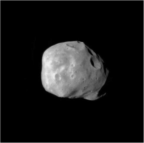
Figure 19.7 Phobos image from Phobos 2 (processing by Ted Stryk).
|
|
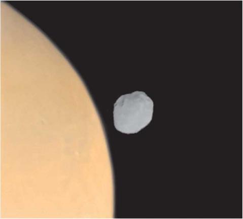
Figure 19.8 Phobos over Mars from the Phobos 2 spacecraft (processing by Ted Slrykl. Phobos:
|
Thirty-seven images of Phobos were obtained with a coverage and resolution that complemented the Mariner 9 and Viking results. About 80% of the surface of the moon was documented. Thermal inertia values for the surface were determined from the thermal emission spectrum, highlighting some inhomogeneities. The reflectance from the ultraviolet through the near-infrared (i. e. 0.3 to 0.6 and 0.8 to 3.2 microns) at a spatial resolution of 1 km appeared to indicate a more carbonaceous chondrile composition than a water-rich chondrile, and also indicated strong inhomogeneities on the surface. Perturbations of the spacecraft’s orbit by Phobos provided a value for the mass of the moon which, together with a volume derived from imagery, gave a density in the range 1.85 to 2.05 g/cc. This was a low value even for a primitive volatile-rich meteorite, and suggested that Phobos might be more porous, or contain more ice, than expected. The temperature of the sunlit surface was 27°C. There were enticing indications from the magnetometer during close passes that the moon might possess a weak magnetic field.
|
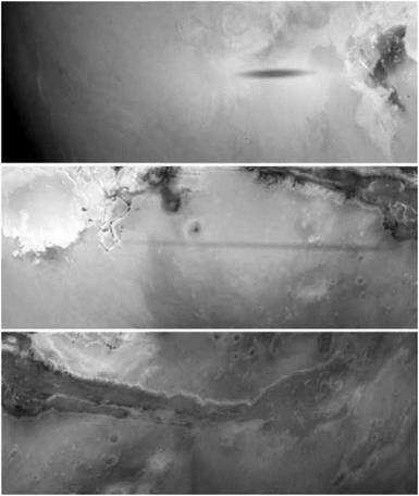
Figure 19.9 TERMOSKAN panorama of the Martian equatorial region front Olympus Mons to Valles Marineris through the red filter. Note the ‘trailed’ shadow of Phohos as it moves across the surface during the exposure.
|
Mars:
Phobos 2 had an array of instruments for multispectral investigations. Limb-to-limb photometric profiles were obtained using a prism spectrometer in the visible at about 25 km resolution, with matching profiles in the thermal infrared (5 to 60 microns) at about 50 km resolution. The data from these two instruments provided information on clouds and aerosols in the atmosphere and temperature profiles at altitudes in the 10 to 30 km range. Information was gained on optical depths, the sizes of particles, and the vertical distribution of aerosols. The occultation spectrometer saw a day-today variability in the atmospheric ozone profile, and a large altitude variation in the water vapor mixing ratio. Water vapor vertical profiles between 20 and 60 km were measured for the first time. The vapor content of the atmosphere was only 0.005%. Mars appeared to be losing its atmosphere at a rate of 2 to 5 kg per second, which
|
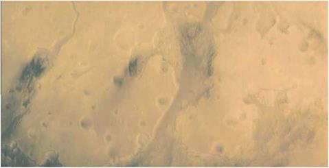
Figure 19.10 Detail from a TCRMOSKAN image in the far-infrared (courtesy Ted Strylt).
|
was fairly significant given the low atmospheric mass; this was equivalent to losing a global ocean to a depth of 1 to 2 meters.
Imaging of the surface of Mars was conducted at thermal wavelengths (8 to 12 microns) with about 2 km resolution using pixel-by-pixel coincident visible-infrared (0.5 to 0.95 micron) images, and the near-infrared mapping spectrometer provided multispectral images at spatial resolutions between 5 km at the low periapsis of the initial orbit and 30 km at the higher altitude of the circular orbit. The thermal data covered most of the equatorial region. The thermal imagery was less sensitive to the atmospheric haze, and showed the same surface features as in the visible range but with sharper contrast, emphasizing the pervasiveness of atmospheric haze on Mars. The measured surface temperatures ranged from -93°C to + 30′ C. Surface thermal inertia from the passage of the shadow of Phobos indicated that there must be a good insulating material down to a depth of 50 microns and poorer insulation below. The near-infrared mapping spectrometer provided data for most of the major geological formations on Mars except the polar regions. Data on the mineralogy of the surface and its local variations revealed a more pronounced variability than was apparent in Earth-based studies. Two bands were of particular interest, the 3.1 micron band of hydrated minerals and the 2 micron band of carbon dioxide, and some contour maps were derived from carbon dioxide measurements.
Gamma-ray spectroscopy conducted during the first four low periapsis passages in the initial orbit provided data on bulk elemental abundances that were consistent with results from Mars 5 and also the x-ray fluorescence measurements made by the Viking landers. Due to its extensive instrumentation, Phobos 2 was able to make a detailed survey of the plasma environment around Mars and how this interacted with the solar wind. No permanent intrinsic planetary magnetic field was measured, even at the low periapsis of the initial orbit. The SLED detector showed levels of radiation in orbit around Mars to be less than limits that would be dangerous to humans.


 Launch mass: