Category Paving the Way for Apollo 11

THE SOUTHERN HIGHLANDS

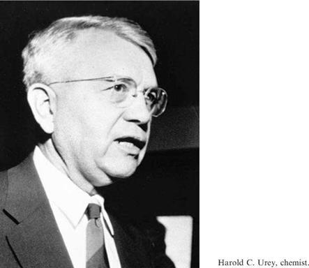
The successful mission of Surveyor 6 completed all requirements established for the project in direct support of Apollo landing site selection. Nevertheless, the Office of Space Sciences and Applications decided to fly the final mission. The target was hotly contested. It was decided that the most important objective was to investigate a site as different as possible from the maria already visited, and preferably a site that offered the greatest likelihood of being different in terms of geology and chemistry. Harold Urey had proposed that the Moon was ‘pristine’ material condensed from the solar nebula and therefore must have an ultrabasic composition, but several lines of evidence implied that the maria were volcanic lava of a basaltic composition. H. H. Nininger proposed in 1936 that ‘tektites’ were ejected by impacts on the Moon and had acquired their aerodynamic shape and a glassy skin during hypersonic entry into the Earth’s atmosphere. But their acidic composition posed a problem. The viscosity of an acidic magma such as granite is several orders of magnitude greater than that of basalt. If the tektites originated from the Moon, they must therefore represent the highlands.[39]

The 85-km-diameter crater Tycho in the southern highlands was widely believed to be the result of a hypervelocity impact but Jack Green thought it was a volcanic caldera, and there were a variety of intermediate theories speculating that an impact promoted volcanism. Because the prominent system of bright rays indicated it to be the youngest crater of its size on the near-side of the Moon, it ought to be relatively uncontaminated by ejecta from elsewhere. Infrared observations made during a lunar eclipse on 19 December 1964 had shown Tycho to be one of the most striking of the thermal ‘anomalies’, implying that there would be lots of rocks on the surface out to a distance of one crater’s diameter beyond the rim crest. It was also bright at radar wavelengths, which also implied rockiness. Lunar Orbiters 4 and 5 had photographed the crater and its immediate environs from an overhead perspective at high resolution. It was decided to aim for a point 30 km north of the rim crest. But a

‘target’ was a circle within which the vehicle had a given probability of landing, and in such rough terrain it proved necessary to trim the diameter of the circle from 60 km to 20 km, which offered barely 10 per cent of the area and would require an extremely accurate trajectory.

It was decided to select a backup target at a similar longitude in order to have the same illumination for surface operations, and make the choice of which target to aim for in-flight by the accuracy of the translunar injection. If the trajectory was unlikely to yield the accuracy required for Tycho, the spacecraft would be diverted to a site in the Fra Mauro Formation. Although this blanket of ejecta lying peripheral to the Imbrium basin would be hummocky and heavily cratered, it ought to be much less demanding than Tycho, and a landing there offered the prospect of determining the composition of material excavated from many tens of kilometres beneath the surface – perhaps even subcrustal material whose chemistry would provide valuable insight into the interior of the Moon. But because the Fra Mauro Formation was ‘ancient’, it was probably contaminated by ejecta from elsewhere. The target was at 13°W, 5°S, just northeast of the 95-km-diameter crater Fra Mauro, and the target circle was the usual 60 km in diameter.

Surveyor 7 was launched at 06:30:01 GMT from Pad 36A on 7 January 1968. For the first time in the series, Gene Shoemaker went to watch the launch. The Centaur achieved orbit at 06:39:54. Owing to the predawn launch, the vehicle emerged from the Earth’s shadow at 06:50:19. It reignited at 07:02:15, shut down at 07:04:15, and released the spacecraft at 07:05:16. Because the decision about the target was to be delayed until after the performance of the Centaur had been ascertained, the nominal aim point for the translunar injection was Hipparchus, near the centre of the disk. It was decided to aim for Tycho. The midcourse manoeuvre at 23:30:09 on 7 January lasted 11.4 seconds, and the change in velocity of 36.4 ft/sec placed the interception point within the target circle. The trajectory was so accurate that an optional second refinement was cancelled.

A study of Tycho and its immediate environs had been made using the medium – resolution pictures taken by Lunar Orbiter 5. On average the rim crest stood 2.5 km above the surrounding highlands, but this was difficult to specify since there was no level plain for reference. The floor of the crater was 4.5 km below the rim crest. The prominent central peak rose over 2 km above the floor, and had hills nestled close alongside it. The theory of impact crater formation implied the central peak complex was a mass of rock thrust up from a great depth by the ‘rebound’ in the final stage of the process. The interior wall was a series of terraces produced when large blocks of material slumped on steeply inclined concentric faults. The high-resolution pictures from Lunar Orbiter 5 revealed the presence of flow features in low-lying areas of the wall terracing, and on the crater’s floor. The exterior was an annular belt 80-100 km wide that could readily be subdivided by albedo and texture into several geological facies.[40]

The innermost of the concentric rings extended from near the crest of the rim out to about 10-15 km, was asymmetric, widest on the northern side of the crater, and comprised irregular hills and intervening depressions which presented a hummocky texture. It contained many well-developed flow features, some as long as 8 km. The second ring, extending from 15 km out to 35-40 km, comprised subradial ridges and valleys, with the ridges typically 2-5 km in length and 0.5-1 km in width, etched on broad undulations 5-20 km across that were recognisable as craters swamped by the ejecta from Tycho. The inner ring had an albedo of 16-17 per cent, and the second was darker at 13-14 per cent.5 Most parts of the rim and the inner two rings were broken by closely spaced radial, arcuate and circumferential faults. Displacements on the radial faults had produced many small radial ridges and troughs interpreted as horsts and grabens respectively. Next was a ring of closely spaced craters ranging from one to several kilometres in diameter that were made by the fall of individual blocks of ejecta from Tycho. Beyond, out about as far as 100 km – a little over one crater’s diameter – the ejecta was discontinuous and transitioned into the system of rays composed of smaller craters which were much less closely spaced. The pictures from Ranger 7 showed a ray from Tycho crossing Mare Nubium to comprise craters ranging in size from 100 metres to 1 km. The thickness of the ejecta was expected to range from several hundred metres near the rim crest, where the ‘hinge flap’ placed the material excavated from the deepest point, to only a few metres in the peripheral zone. At Surveyor 7’s target, on the second ring, the ejecta was expected to average several tens of metres in thickness.

The pre-retro manoeuvre in which the spacecraft departed from its cruise attitude involved starting a roll of +80.5 degrees at 00:27:17 on 10 January, a yaw of +96.1 degrees at 00:35:52 and a roll of-16.5 degrees at 00:41:09. The initial approach was at 34.8 degrees to the local vertical. The altitude marking radar was enabled at 01:00:33.7, and it issued its 100-km slant-range mark at 01:02:11.892. The delay to the initiation of the braking manoeuvre was specified as 2.775 seconds.

The verniers ignited precisely on time, and the retro-rocket 1.1 seconds later. At that time the vehicle was travelling at 8,580 ft/sec. The RADVS was activated at 01:02:15.752. The acceleration switch noted the peak thrust of 9,200 pounds fall to 3,500 pounds at 01:02:58.973, giving a burn duration of 42.9 seconds. The verniers were throttled up to their maximum thrust at 01:03:09.250 for 2 seconds while the motor was jettisoned. At burnout, the angle between the vehicle’s thrust vector and velocity vector was 19 degrees. The RADVS-controlled phase of the flight began at 01:03:13.090, when the slant range was 51,259 feet (and because the velocity vector at burnout was offset to vertical, the altitude was 41,510 feet) and the total velocity was 452 ft/sec (and since the vehicle had maintained its thrust along the velocity vector extant at the time of retro ignition, the longitudinal rate was 428 ft/sec). The vehicle immediately aligned the thrust axis along the velocity vector extant at retro burnout

The descent of the Surveyor 7 spacecraft depicted in two sections, one for slant ranges above 1,000 feet and the other below 1,000 feet.

and flew with the verniers at 0.9 lunar gravity, very slowly accelerating as it descended. When the altimeter locked on at 01:03:17.649, at a slant range of 41,673 feet, attitude control was switched from inertial to radar and the thrust axis was swung in line with the instantaneous velocity vector to initiate the gravity turn. On intercepting the ‘descent contour’ at 01:04:03.018, the slant range was 20,246 feet and the speed was 464 ft/sec. By the 1,000-foot mark at 01:05:13.285, the vehicle was descending very nearly vertically at 102.5 ft/sec. The 10-ft/sec mark was issued at 01:05:30.184 at a height of 46 feet.

The verniers were cut off at 01:05:36.284, and after falling freely the vehicle touched down at 01:05:37.620 with a vertical rate of 12.5 ft/sec and a lateral rate of 0.3 ft/sec. Leg no. 1 was the first to make contact, followed rapidly by legs no. 2 and 3 in that order. There had been a fair chance that the vehicle would be disabled on trying to land in such rough terrain, so its survival gave rise to wild applause in the Space Flight Operations Facility.

The camera was of the type introduced by Surveyor 6 – the hood was of the boxy configuration, the elevation range of the mirror was 70 degrees, and it had polarising filters. The first 200-line picture was sent at 01:47. After 15 pictures had been taken for a preliminary study, the solar panel and high-gain antenna scanned for the Sun and Earth respectively, locking on by 03:21. The first 600-line picture was taken at 03:42. The foot pads had displaced as the legs rebounded on contact, but overlapped their original imprints. Pad no. 2 had nudged aside a rock that was about 18 cm long and at least 10 cm high. Pad no. 3 landed partially on top of a semi-buried rock, and in the process suffered localised deformation and tearing. The pads had penetrated to a depth of 4 cm and displaced clods to a radius of about 40 cm, but there was barely any lunar material on their upper surfaces. As on the maria, the disturbed material was darker than the undisturbed surface. The orientation of the lander put the camera on the north-facing side. To the east, south and west the horizon was less than 200 metres away, but because the local surface sloped down to the north the view in that direction was spectacular, with a succession of ridges on the horizon. Despite being the roughest-looking target to date, the landscape still bore little resemblance to the depictions of the lunar surface in contemporary popular fiction. The slope on which the lander stood was about 3 degrees. Most of the landscape on view was no steeper than 10 degrees. The steepest flank of a ridge on the horizon was 34 degrees, and the summit was rounded.

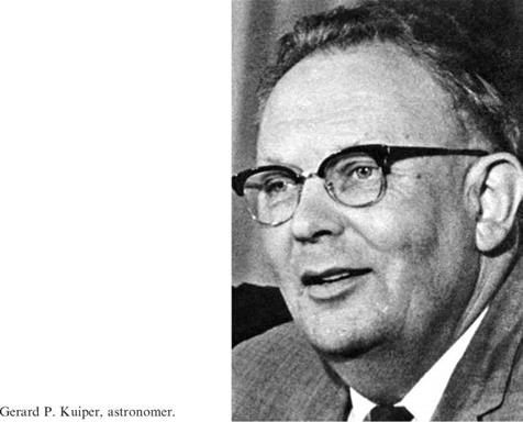
It turned out that Surveyor 7’s trajectory was very accurate and it landed a mere 2.5 km from the aim point. The coordinates were difficult to determine because the selenographic grid presumed the Moon to be spherical, which was not the case. For points above the mean sphere and situated some distance from the centre of the lunar disk, the measured coordinates were greater than the actual coordinates. Also, at this location the latitudinal circles were significantly curved. This complicated the drawing of a local grid. Instead, features on frame M-128 from Lunar Orbiter 5 were identified on a picture taken in 1919 by the 100-inch telescope at the Mount Wilson Observatory, and the site pin-pointed on M-128 was transferred first to the telescopic picture and then to the coordinate system of the relevant sheet of the Orthographic Atlas of the Moon (based on that picture) which had been issued by D. W.G. Arthur and E. A. Whitaker in 1961 as a supplement to the Photographic Lunar Atlas produced by Gerard Kuiper.

A number of geological units were identified in the high-resolution pictures taken by Lunar Orbiter 5. The most widespread unit was described as ‘patterned debris’. This was the major unit of the second ring of ejecta deposits. The size-frequency distribution of craters exceeding 8 metres in diameter was the highest of all the units in the ejecta debris.

To the lander, the patterned debris extended several tens of kilometres to the west, north and northeast, and the large craters had raised rims which, in many cases, were relatively smooth. This was well demonstrated by a crater about 650 metres to the north that was 60 metres in diameter. Although it was 10 metres deep, its rim was smooth. It was apparent that the patterned debris was a blanket of unconsolidated material. The crater contained a few large blocks, but they were no more numerous than were lying around between the craters. The absence of strewn fields associated with craters on the patterned debris indicated it to be at least 20 metres thick, which

The northward-looking portion of a panorama taken by Surveyor 7. The outline shows the area covered by the next illustration. (Courtesy of Philip J. Stooke, adapted from International Atlas of Lunar Exploration, 2007)

Three ridges at successively greater distances to the north of the Surveyor 7 lander. The letters are explained in a subsequent Lunar Orbiter illustration. (Courtesy of Philip J. Stooke, adapted from International Atlas of Lunar Exploration, 2007)

A portion of frame H-128 by Lunar Orbiter 5 showing where Surveyor 7 landed.

A preliminary geological map of the immediate vicinity of the Surveyor 7 landing site, produced by E. M. Shoemaker and E. C. Morris of the US Geological Survey.

was consistent with expectation. Surveyor 7 actually set down about 50 metres from the western margin of a ‘patterned flow’, beyond which was the dominant patterned debris. There was no relief at the contact between the two – the difference evident in overhead imagery was only a distinction in the surface texture. The patterned flow extended to the north and east, but most of it was to the south of the lander and hence beyond the near horizon, which was only a few hundred metres off. In the Lunar Orbiter pictures, the surface of the flow comprised low hills and depressions ranging up to several hundred metres across. But superimposed on these broad irregularities was a pattern of north-trending low ridges and grooves similar to those on the patterned debris (but less well defined) with swarms of fissures running along the ridges which suggested they had undergone slumping. There were a great variety of rock fragments in the vicinity of the lander, ranging up to 1 metre in size. Two craters to the southwest of the lander – one 20 metres in diameter and the other 30 metres – had rims littered by coarse blocks up to 75 cm in size. They were on the patterned flow, and had excavated these rocks. There was an irregular crater about 3 metres in diameter 5 metres north of the lander that contained coarse blocks up to 60 cm in size and issued a strewn field extending to the northwest, but this crater

was undoubtedly made by the fall of ejecta from another event, and the blocks were the debris of the secondary projectile.

The lander could also observe an area of‘smooth patch material’ to the northeast. Such units occurred in enclosed depressions several hundred metres across and – in addition to being smooth – were relatively dark. The fact that the smallest crater on this material to have a blocky rim was only 5 metres in diameter indicated a source of rocks at a depth of about 2 metres. As this particular smooth patch material was superimposed on the patterned flow, the craters had undoubtedly punched through to the patterned flow. This in turn indicated that this particular spot of smooth patch material was a thin veneer. On all three types of terrain, most of the craters with diameters in the range 8 to 16 metres were elongated with their major axes radial to Tycho.

The principal difference between the patterned debris and the patterned flow appeared to be that whereas the patterned debris material rapidly settled on being ballistically deposited, the patterned flow gained its distinctive texture by flowing for distances ranging between several tens and several hundreds of metres.

In the immediate vicinity of Surveyor 7, small craters were as abundant as on the maria, but the size-frequency distribution of those exceeding 10 metres across was significantly less. There was a greater variety of rock types than at any of the maria sites, and they varied in albedo up to 22 per cent. Some blocks were plain, but others were spotted. The spots were of various sizes, had irregular margins, and appeared to be surface protrusions. One particularly striking rock 2 metres away had spots that ranged in size from less than 1 mm to about 30 mm and covered about 30 per cent of the visible face. It was speculated that the spots were fragments of light-toned rock assimilated into a dark matrix – a mechanically assembled conglomerate known as a breccia. Some rocks had well-developed linear structures, and others appeared to be vesicular – both of which were suggestive of lava.

The maria were lava flows that solidified as coherent rock and were subsequently progressively pulverised by meteoroid bombardment to accumulate a regolith which matured over time into ever finer fragments. Although the excavation of Tycho laid down a blanket of ejecta, it did so essentially instantaneously. Such material would contain blocks of all sizes with a size-frequency distribution different to a regolith. Some blocks would have come to rest on the surface as the ejecta was laid down, but most would have been buried. Some would later be excavated and tossed around. If (as the superposition relationships indicated) Tycho was formed recently, then there could not have been much time for the rain of meteoroids to produce a true regolith on top of the ejecta blanket. A theoretical study which incorporated all that had been learned to date about the rates of small impactors, predicted that the regolith at this site ought to be about 10 cm thick on average.

In early 1967 the plan was to fly the soil mechanics surface sampler on Surveyors 3 and 4, and then the alpha-scattering instrument on the remaining missions. But it had been decided that Surveyor 7 should have both. The intention was to conduct an elemental analysis of undisturbed surface, then activate the sampler and use this to reposition the sensor head to analyse subsurface material excavated by the arm. The alpha-scattering instrument was powered up at 09:28 on 10 January. The

MAGNET AND CONTROL BAR

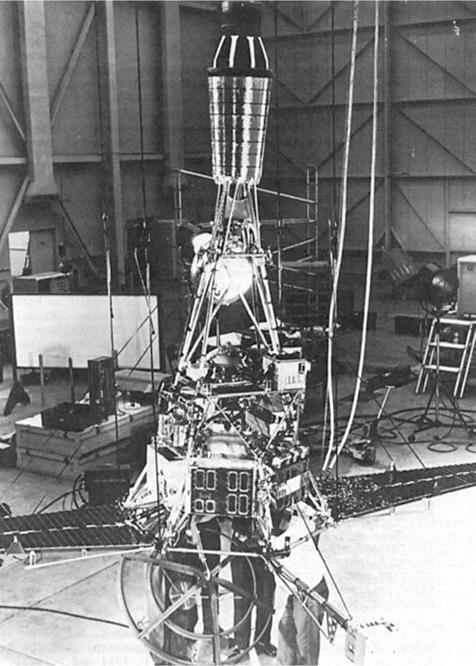
The configuration of the Surveyor 7 lander.

standard sample was measured between 09:28 and 15:29, yielding 5.2 hours of data. At 15:49 the standard sample was removed to enable the head to measure the background, and 4.8 hours of data was obtained between 16:13 and 21:59. The auxiliary mirror on leg no. 1 orientated to provide the camera with a line of sight beneath the vehicle in order to investigate where the head of the alpha-scattering instrument would take its first sample showed a uniform grey; evidently during the landing it had been completely coated with fine-grained material! There was a partial coating on the mirror for viewing crushable block no. 2, but it was still possible to establish that there was an imprint. The area beneath block no. 3 was in the lander’s shadow for most of the time. The command to release the head was issued at 22:01 on 10 January. The instrument’s counts were monitored in real-time for 6 minutes, awaiting the increase that would confirm that the head was on the surface; but there was no change. The command was reissued at 22:09 and the counts monitored for 10 minutes – again with no increase. A series of pictures taken between 22:41 and 23:44 of the head and the deployment mechanism showed that the squib had fired, the pin had been pulled and the door of the cable compartment was open. However, the head had not moved. It was concluded that the escapement mechanism for the nylon cord had either failed to function or the cord had become stuck in the mechanism. It was decided to activate the arm and try to use this to lower the sensor head.

The soil mechanics surface sampler was powered up at 01:00 on 11 January, then exercised to verify its functionality. To enable the arm to manipulate the head of the alpha-scattering instrument, its mounting structure had been redesigned to draw the arc of its azimuth range to the left; but this was at the expense of the other end of its range, with the result that it could no longer reach foot pad no. 2. On Surveyor 3, an

attempt had been made to measure the force that was applied by the arm but the time-resolution of the motor current telemetry had been insufficient to provide an accurate measure. Originally, the motor current readout had allowed a maximum of eight current samples for a 2-second motor actuation. The upgraded system provided samples at 50-millisecond intervals. In a static bearing test the arm would lower the flat face of the scoop’s door over the selected spot using a series of either 0.5 or 2.0- second commands until the elevation motor stalled, indicating the force against the surface. When driving the scoop into the surface with its door open for trenching, it would be possible to measure bearing strength as a function of depth.

After the arm had made two bearing tests well clear of where the alpha-scattering instrument was to sample – in the process obtaining readings very similar to those at the Surveyor 3 site, where an identical test had been made – the arm began its efforts to deploy the balky instrument. Between 07:23 and 08:09 the arm was manipulated until it rested its scoop on the base plate of the head, and then from 08:15 to 08:50 it applied a series of light taps to the plate. It had been hoped that this would cause the head to unreel all the way down to the surface, but TV pictures showed that it swayed on its cable without unreeling. It had not, in fact, been possible to impart much downward force because with the head dangling freely on its cord a force applied to one side of the plate simply caused the head to tilt and swing away. Further pictures were taken between 23:14 and 23:41 to inspect the escapement mechanism.

On 12 January the arm began its day with another three bearing tests, and then manoeuvred to pick up a rounded rock (Rock ‘A’) that was about 5 cm in size, with

the motor current being monitored to estimate the mass of the rock. Between 05:48 and 07:33 the arm was first positioned alongside the right-hand side of the head and then manipulated using a procedure that had been tested on an engineering model to jam the head against the helium tank to the left, to prevent it from swinging when a downward force was then applied. In driving the head down by several centimetres, sufficient room was gained to position the scoop directly above the head, near the eye-bolt to which the cable was attached. This was achieved by 08:01, and between 09:11 and 10:05 a downward force was applied to drive the head against the tension of the fouled cord all the way down to the surface. During the hiatus, the instrument had obtained an additional 7.2 hours of background data. There were a number of fairly large fragments on the surface close to where the head deployed, and in fact not only was there a rock some 4 cm in size under the inboard side of the base plate that was tilting the head, there was also a fragment of about 1.5 cm in the aperture at the centre. The analysis of sample 1 started at 16:42 on 12 January, and 6.2 hours of data had been acquired by the end of the day.

On 13 January the arm made an attempt to lift Rock ‘B’, but this proved to be just out of reach. Instead, Rock ‘C’ was scooped up, but when the arm was elevated to weigh the rock it fell out of the scoop. Trench 1 was made at the extreme right of the arm’s operating area. This was foiled by a subsurface obstacle at a depth of 2.5 cm which proved able to resist the retraction motor on two scrapes, with the result that the penetration was limited to 5 cm. This obstacle proved to be a buried rock with an irregular upper surface. The alpha-scattering instrument had to be switched off early on 13 January when the head exceeded its maximum operating temperature of 50°C, but data-taking resumed at 10:55 after the arm positioned its scoop to shade the head and allow it to cool off. There was a hiatus between 20:21 and 22:36 while the scoop again provided shade, and operations ended at 23:33. The arm devoted the whole of 14 January to Rock ‘D’. At first sight this appeared as a rounded knob poking out of the surface and sufficiently small to fit into the scoop for weighing, but when it was excavated it proved to be too large. The angular shape of the buried portion of the rock was an indication of the efficiency of the erosional process that had rounded off its exposed face.

Some alpha-scattering data was obtained on 14 January, but for most of the time the head exceeded its maximum operating temperature. When the lander arrived, 30 hours after sunrise, the Sun was at an elevation of 13 degrees. At the equatorial sites visited by previous missions the Sun passed close to the zenith at noon, but at this site its maximum elevation was 48 degrees above the northern horizon. A pre-flight study indicated that the surface temperature at noon would be approximately 100°C, as opposed to 127°C on the equator, but the analysis presumed a smooth surface and did not take account of local influences such as slopes, craters and blocks that could not be predicted in detail. Although the incident heat would be less harsh at this site, the fact that the Sun did not pass near the zenith meant that the shadow of the mast – mounted panels never fell on the vehicle. As a result, the scientific payload, which faced north, grew hotter during the mid-morning, noon and mid-afternoon than at any previous site, and both the head of the alpha-scattering instrument and the electronics of the sampling arm exceeded their maximum operating temperatures.

scattering instrument and the soil mechanics surface sampler were all exposed to the Sun

as it tracked across the northern sky.

For the three days during the mid-day period, therefore, the arm only manoeuvred to maintain the shadow of its scoop on the head in an effort to keep this below its ‘survival limit’ of 75°C – which was only just achieved. The thermal stress on the camera was worse than on earlier missions, as at noon the Sun shone on the side of the cylinder rather than down upon its top. It was rotated in azimuth away from the Sun to minimise the solar absorption by the black interior of the hood. During the 5- day period near local noon its use was severely restricted – at worst to only 5 minutes per hour.

Arm work resumed on 19 January by re-weighing Rock ‘A’. A flat 22×60-cm mirror just below the upper collar of the mast allowed the camera to view a roughly triangular area of about 0.25 square metres lying between 1.7 and 3 metres from the camera, a portion of which was accessible to the sampling arm. Carrying the rock, the arm swung into the field of view of the mirror and stereoscopic pictures were taken to enable the volume of the rock to be estimated and, in turn, the density. With a density in the range 2.4 to 3.1 g/cm3 – the most likely value being in the range 2.8 to 2.9 g/cm3 – the rock could not be very porous. The arm was then elevated to drop the rock from a height of about 60 cm – after making a small indent in the surface, it bounced or rolled about 12 cm. The strength of this rock was tested by having the scoop squeeze it, but it did not break. The arm then retrieved the rock and deposited it closer to the head of the alpha-scattering instrument – in preparation for possibly placing the head on top of the rock to determine its elemental abundance and further characterise it.

camera and indirectly from a position corresponding to the virtual image of the camera in the mirror mounted on the mast.

On 20 January the arm made trench 2 using four scrapes. A buried obstacle near the start of the trench deflected the scoop to the left. Once finished, the trench was 75 cm long and varied in depth between 15 and 18 centimetres. Trench 3 was placed close alongside as a single scrape. In scraping trench 4, the scoop’s door was kept closed in order to measure the ability of the surface to resist lateral force. In addition to having magnets on both foot pads no. 2 and 3, Surveyor 7 had a pair of horseshoe magnets embedded in the door of the scoop. In fact, the pads penetrated only 6 cm, which was insufficient to bring the magnets on their sides into contact with the lunar material. However, the magnets on the arm were able to test selected spots. As these magnets repeatedly came into contact with the lunar surface they attracted material with a granularity finer than the resolution of the camera, which was about 1 mm at that distance. As an experiment, the scoop was nudged against a chip of rock about

1.2 cm in size that had a smooth shape, a low albedo and a lustre. When the scoop was raised, the rock clung to the magnets on the door. Prior to being disturbed, this rock was partially embedded, with no evidence on the surface of it having landed or rolled into position. The fact that its exposed surface was much darker than most of the rocks in the arm’s operating area implied that it was atypical. Its strong magnetic susceptibility would have been consistent with a nickel-iron meteorite or a material rich in magnetite – it was not possible to say which (if either). Unfortunately, as the arm was manoeuvred to facilitate stereoscopic photography the acceleration caused the fragment to fall off.

The alpha-scattering instrument was reactivated at 21:14 on 20 January and found to have cooled down to 40°C, so data-taking was resumed. By 07:21 on 21 January it had accumulated a total 27.3 hours of data for its first sample. With two days remaining to sunset, it was decided to reposition the head. On previous missions the cord was attached to an eye-bolt installed directly on the head’s upper surface, but this time it was attached to a knob that had been designed to enable the arm to grasp the head. On 21 January, the scoop lifted the head. The motor current was monitored in order to provide a calibration check of this method of weighing rocks. The plan to analyse Rock ‘A’ had been rejected in favour of an undisturbed rock – the one selected was adjacent to Rock ‘D’. It was lighter in tone than its surroundings and about 5 x 7 cm in size. In manoeuvring the head the arm caused the rock to shake, which indicated that it was sitting on the surface rather than embedded in it. The arm engineers were delighted with the precision of its movements. At 12:30 the head was left perched on the rock. In fact, part of the rock protruded through the aperture into the cavity of the head. The instrument analysed the ‘exposed’ upper surface of the rock for 10 hours. Meanwhile, the arm scraped first trench 5 with the door open and then trench 6 with the door closed. On 22 January the arm excavated trench 7 in between the trenches scraped the previous day – again with the door closed. With three trenches in close proximity, there was a significant amount of debris piled up at their inner ends. The alpha-scattering instrument was moved onto this disturbed material and 6.7 hours of data was obtained between 12:06 on 22 January and 14:40 on 23 January, which was some 8.5 hours after sunset, and by the time it was switched off at 15:36 the head of the instrument had chilled down to -20°C and the associated electronics to -50°C.

While the alpha-scattering instrument was performing its third analysis, the arm made a series of bearing tests – one of which was adjacent to trench 2, with pictures being taken to look for any evidence of the wall of the trench collapsing in response to the pressure. Then it was decided to attempt to crack open a rock to obtain a fresh surface which could be photographed using the polarising filters to seek insight into its structure. The arm positioned the scoop directly above Rock ‘E’, raised the scoop to a height of about 35 centimetres and let it fall with its door open on the rock. The rock was about 5 cm in size, and the impact broke off a small piece – either because it was intrinsically weak or because it contained a fracture. While scraping trench 1, the arm had been fouled by a buried rock, so as a finale the scoop was lowered back into this trench and the arm retracted to re-engage the obstacle. Then after sunset on

A picture taken at 11:21 GMT on 22 January 1968 showing Surveyor 7’s sampler repositioning the alpha-scattering instrument in preparation for its third sample.

23 January, exploiting the increased torque of the retraction motor as a result of it having chilled to -110°C, the arm tried to dislodge the rock. However, the fact that the applied force partially compressed the shock absorber on leg no. 2 indicated the rock to be firmly embedded! This final experiment over, the arm was switched off at 08:41 that same day.

Over a total of 36.3 hours of operation the arm made 4,397 mechanical motions. It made two impact tests, seven trenches, two of which used more than one scrape, and sixteen bearing tests, five of which were with the scoop door open. One of the trenches was directed by a command tape which took a picture between each action, and the frames were later compiled into a movie. There were fragments up to 10 cm

in size within the arm’s reach, most of which seemed to be dense coherent rock. The subsurface was predominantly fine-grained granular material but, as was revealed by the trenching, there were fairly large rocks at a shallow depth. As on the maria, the fine-grained material was slightly cohesive, partially compressible and consolidated with depth. The fact that the undisturbed surface was brighter than the subsurface on both the maria and in the highlands indicated that this was not simply a property of the maria but a universal weathering process. Whereas on the maria the albedo of the undisturbed surface was 7.2 to 8.2 per cent and the subsurface was 5.5 to 6.1 per cent, in this case the undisturbed surface was 13.4 per cent and the subsurface was 9.6 per cent. The fact that at this site the subsurface was slightly brighter than the undisturbed surface of the maria was probably a consequence of the highlands being generally brighter than the maria.

From the point of view of the alpha-scattering investigation, Surveyor 7 was the most productive mission, with the increase in yield being derived from collaboration with the sampler. In fact, fully 8.75 hours of the arm’s operating time was devoted to deploying and subsequently tending to the alpha-scattering instrument.

The high latitude and the increased elevation range of the camera’s mirror enabled narrow-angle pictures to be taken of Earth. On its first day of operation, the lander photographed Earth through polarising filters – the first time this had been done, and the highly polarised component was inferred to be specular reflection of sunlight by the ocean.

An experiment assigned to the first Apollo lunar landing mission was to emplace on the lunar surface an instrument that comprised an array of corner-cube reflectors designed to reflect a laser beam fired from Earth back towards its source, so that the intervening distance could be precisely measured to analyse the secular components of the Moon’s motion.6 To test the first stage in this process, Surveyor 7 was to take pictures of Earth while laser beams were being fired. Six sites were established, each with a laser directed through a telescope to reduce the divergence of the beam during its transit to the Moon. The first test on 14 January was a failure. After a pause while Earth and the Sun were close together in the lunar sky, the experiment resumed on 19, 20 and 21 January. The first clear detection was on 20 January, with the pictures simultaneously capturing the beams from the 60-inch McMath solar telescope of the Kitt Peak National Observatory, Tucson, Arizona, and the 24-inch telescope of the Table Mountain Observatory – the latter operated by JPL in Wrightwood, near Los Angeles, California. Although the power of the lasers was just 1 to 2 watts and they illuminated a footprint on the lunar surface that was about 3 km in diameter, which had the effect of diluting the energy across a wide area, to the lander’s camera they appeared against the dark part of the crescent Earth as points of light rivalling Sirius, the brightest star in the sky.

Because the Moon rotates once in the same time as it takes to pursue one orbit of

А З-second exposure taken by Surveyor 7’s camera at 09:06 GMT on 20 January 1968 recorded laser beams fired at it by two telescopes on Earth. The lasers were fired by the Kitt Peak National Observatory near Tucson, Arizona, and the Table Mountain Observatory near Los Angeles, California. They are indicated by black circles on the globe (left). Owing to the long-exposure required to detect the laser beams, the illuminated part of Earth is washed out.

Earth, our own globe remains more or less stationary in the lunar sky, rotating on its axis on a 24 hourly basis and waxing and waning in illumination over the period of a month. Starting at 17:11 on 22 January, the lander took sets of pictures of Earth through polarising filters at 2-3-hour intervals over a period of 26 hours. The goal was simply to determine what such observations could discern, starting with how the reflectance of the atmosphere varied as a function of the changing cloud distribution over one diurnal period.

It had been hoped to make at least one ‘hop’, and the predicted windows for this were when the elevation of the Sun was climbing between 23 and 31 degrees in the morning and falling between 23 and 16 degrees in the afternoon, but even at these times parts of the vernier propulsion system were too hot. Because leg no. 2 was on the north side of the vehicle, it suffered the longest period of direct illumination. The thrust chamber assembly of vernier no. 2 exceeded its pre-ignition temperature limit in the morning – in fact, it grew hotter than any engine on any previous vehicle. And before this engine could cool in the afternoon, vernier no. 3 had grown too hot. Only vernier no. 1, on the south side, remained usable in this respect. Furthermore, the temperature of the shock absorber on leg no. 1 plummetted to -53°C, well below the minimum temperature at which it could be expected to work properly during a hop. With leg no. 2 cooling in the afternoon, at 23:55 on 20 January the temperature of vernier no. 2 sharply dropped from 31°C to -18°C. At the same time there was an increase in the temperature of the fuel line indicating a flow from the tank, which was at 70°C. The engine was being chilled by the vaporisation of fuel leaking from the shutoff valve poppet. At 17:21 on 22 January the helium regulator automatically opened in a fruitless effort to re-establish the fuel pressure. The shock absorbers of the legs had not been locked following landing, but at 15:32 on 21 January, with no prospect of attempting a hop, they were commanded to lock. The squibs fired, but at sunset leg no. 2 deflected 2.4 degrees, indicating that it had failed to lock.

Sunset occurred at 06:06 on 23 January. Over the next 15 hours the camera took further pictures of the Earth, stars and the solar corona. Exposures of 20-30 minutes detected the corona out as far as 50 solar radii, which was about five times further out than was feasible for a solar eclipse viewed from Earth – sufficiently far, in fact, to study the hitherto unobservable transition zone between the solar corona and the inner zodiacal light zone. The pictures taken during the first 90 minutes after sunset provided further evidence of the ‘horizon glow’ discovered by Surveyor 6. When viewed from the equator the glow had remained due west, but for Surveyor 7, some 40 degrees south, the axis of the glow tended to migrate northward along the horizon with time. As for the cause of this phenomenon, it was concluded that electrostatic levitation of fine dust, if it occurred at all, would be minimal with insolation at a grazing angle. This left diffraction of the last rays from the upper limb of the solar disk approximating a point source on the horizon – as this geometry migrated beyond the local horizon the glow would persist for a time, with the pattern of the gaps in the line changing according to how the lunar surface features lying beyond the horizon cast their shadows onto the local horizon. Camera operations ceased at 21:10, having taken a total of 20,993 pictures.

Less post-sunset temperature data was obtained than hoped, once again owing to problems involving the bimetallically activated switches in the thermally controlled compartments, and the hibernation command was enacted at 14:12 on 26 January, 80 hours after sunset.

Surveyor 7 was reactivated at 19:01 on 12 February, some 120 hours after sunrise on its second lunar day. The shock absorber on leg no. 1 had compressed during the night, causing a deflection of 23.5 degrees – in effect completely collapsing the leg. Leg no. 2 had also compressed at sunset, but the fact that it recovered meant that its deflection had merely been the result of fluid contraction. In the case of leg no. 1, however, it appeared that high-pressure gas had leaked from the shock absorber. The alpha-scattering instrument resumed taking data on 13 February. The following day the arm was sent a single-step extension command, simply to verify that it was still operational. When the camera was activated, it proved unable to scan pictures in the 600-line mode due to an electrical fault. It was still functional in the 200-line mode, but a problem with the rechargeable battery limited its use. Indeed, after 45 frames the rate at which the camera could take pictures had decreased to one per hour and it was decided to cancel further operations. The arm test was successfully repeated on 20 February. By that time the power supply was so critical that the alpha-scattering instrument had to be switched off. The final communication from Surveyor 7 was at 00:24 on 21 February 1968 – there would not be another NASA transmission from the lunar surface until the first landing by an Apollo crew.

During the first lunar day the alpha-scattering instrument was operated for a total of 136.5 hours. This included 310 minutes of calibration using the standard sample, 727 minutes measuring the background (longer than planned, owing to the difficulty in deploying the sensor head) and 64 hours of science data – of which 44 hours was of sample material: 27.3 hours on the undisturbed surface, 10 hours on the rock and 6.7 hours on the subsurface that had been exposed by the arm. On the second lunar day the instrument provided another 34 hours of data for the third sample area over a 35-hour period, but only 20 hours of this were deemed to be usable owing to a low signal-to-noise ratio in the transmission. The total usable surface data was therefore 64 hours.

The main results of the alpha-scattering instrument were that for the fine-grained material the aluminium abundance was higher than measured at the maria sites, and the ‘iron group’ with atomic masses ranging from titanium to nickel were a factor of two less abundant. In the case of the relatively light-toned rock that was analysed the iron content was lower still. On seeing the elemental abundances, some people inferred that the lunar highlands must be an alumina-rich form of basalt, but Gene Shoemaker countered that the dominant rock in the Tycho ejecta – which was drawn from deep within the crust – was anorthositic gabbro. Such a feldspathic rock was a further indication that the Moon had undergone thermal differentiation. The lower iron content suggested that the highlands had a significantly lower density than the mare material. Later, John A. Wood would pick up on this and argue that the Moon had been so hot in the final stage of its accretion as to be molten to a considerable depth. In this ‘magma ocean’, the heavier elements sank to create a magnesium and iron silicate mantle whilst the lighter elements floated to the surface and cooled to create a crust. There was no evidence of the acidic rocks that would be required to
account for the tektites. Overall, the elemental analyses performed by the Surveyors strongly indicated that the Moon was not a pristine body of ultrabasic composition, and this, in turn, ruled against the hypothesis that the most abundant meteorites on Earth – known as chondrites – originated from the Moon.

The Surveyor project achieved its primary objective of yielding sufficient insight into the nature of the lunar surface to allow Apollo to proceed in confidence, free of concern that the lander might sink into a sea of dust or fall through a brittle surface into a subterranean cavity.

Table 14.1: Surveyor sites – selenographic coordinates

Spacecraft Longitude Latitude Description

As derived from Orthographic Atlas of the Moon issued by D. W.G. Arthur and E. A. Whitaker in 1961 as Supplement 1 to the Photographic Lunar Atlas.

Table 14.2: Surveyor landing times and lighting

Spacecraft

Landing time (GMT)

Sun angle (degrees)

Surveyor 1

06:17:36

2 June 1966

28

Surveyor 3

00:04:17

20 April 1967

11

Surveyor 5

00:46:42

11 September 1967

17

Surveyor 6

01:01:04

10 November 1967

3

Surveyor 7

01:05:36

10 January 1968

13

Table 14.3:

Surveyor photography

Spacecraft

1st day

2nd day

4th day

Total

Surveyor 1

10,341

899

11,240

Surveyor 3

6,326

6,326

Surveyor 5

18,006

1,048

64

19,118

Surveyor 6

29,952

29,952

Surveyor 7

20,993

45

21,038

87,674

Note – these are finalised figures from the Surveyor Program Results, SP-184, 1969, which states that it corrects figures in the individual mission reports.

All but one of the successful Surveyor landers examined sites in the Apollo zone.

ROVING PLANS

It had been hoped that Surveyor would advance beyond the Block I engineering model. Planning for the Block II was terminated on 13 December 1966. Each would have weighed about 100 kg more than the original model, and have carried a greater scientific payload. In April 1964 Bendix submitted to JPL the outcome of a 6-month study to assess the feasibility of having a Block III deliver a 45-kg Surveyor Lunar Roving Vehicle. The plan was for the rover to be remotely controlled from Earth as it conducted a systematic study of a site which had been short-listed on the basis of Lunar Orbiter imagery as an Apollo target, to provide the ‘ground truth’ required to inform a final decision. It would be equipped with a scanning and digitising camera

RF RANGING ANTENNA

OMNI ANTENNA

DIRECTIONAL ANTENNA

TRACTION DRIVE ASSEMBLY

Detail of the Surveyor Lunar Roving Vehicle proposed by the Bendix Corporation.

for stereoscopic imagery from which the local relief could be mapped on the scale of interest to the site selectors seeking ‘clear’ areas large enough to accommodate an Apollo lander. The rover would also have a penetrometer with which to measure the roughness and bearing strength of the surface along its route – something that could not be done from orbit. One survey method would involve an ever-widening spiral. It might make several such spirals, driving some distance cross-country in between, in total driving up to 25 km over an interval of several months – working during the lunar day and hibernating at night. There would be a trade-off between conducting a wide-area survey and certifying a given site for an advanced Apollo landing.7 It had been hoped to launch five such missions in the 1970s, but the development funding was never forthcoming.

Note that the plan presumed that an Apollo spacecraft would be able to set down precisely at a preselected point.

THE RENAISSANCE IN ASTRONOMY

In 1330 AD the Italian scholar Francesco Petrarca coined the term ‘dark ages’ for the centuries of cultural decline in Europe after the fall of Rome in the fifth century. Intellectual development did not resume until the start of the Italian Renaissance in the fourteenth century. During this interregnum, the works of classical Greece and Rome were available only in Arabic translation. On being ‘rediscovered’, they were translated from Arabic into Latin.

In 1505 Leonardo da Vinci, who had exceptional eyesight, drew an impression of the face of the Moon. He interpreted the brighter part to be water, the dark areas as land, and believed that there were clouds. He was the first to explain the old-Moon-in-the-new-Moon’s-arms effect that occurs when the Moon is a narrow crescent. At such times the majority of the Earth’s disk in the lunar sky must be illuminated, and the dark part of the remainder of the lunar disk is dimly lit by sunlight reflecting off Earth. Late in the 13th century, it had been realised that light was bent by passing through a glass lens. The term ‘refraction’ was not invented until some time later. In 1490 da Vinci had speculated upon whether lenses could be used in combination to make an enlarged view of a distant object. In 1504 he conducted experiments, and by 1510 had the optical principle of the telescope.

After further experiments, three years later he described how a concave mirror could produce a magnified image.

As the Renaissance progressed, some of the ancient beliefs were questioned. By the Ptolemaic system, all celestial bodies travelled around Earth on a daily basis, but Nicolaus Copernicus, a Polish canon, realised that this was not entirely true. In his book De Revolutionibus Orbium Coelestium he revived the heliocentric system of Aristarchus of Samos. Copernicus said only the Moon travels around Earth, but he retained circular orbits, deferents and epicycles. The planets, including Earth, are in orbit of the Sun. But knowing that the Church of Rome would construe this to be heresy, he kept silent, and his book was not released until after he died in 1543. His caution was justified, as in 1600 Giordano Bruno was burned at the stake in Rome for arguing in favour of the heliocentric hypothesis.

Johann Kepler was born near Stuttgart in Germany in 1571. He went to Prague in 1600 to assist the Danish astronomer Tycho Brahe, who held the title of Imperial Mathematician to the Holy Roman Emperor Rudolph II. Over a period of 20 years Brahe had compiled a highly accurate catalogue of planetary motions. When Brahe died in 1601, Kepler inherited the title of Imperial Mathematician, together with the archive of observations, which he set about analysing – something that Brahe had never attempted. Brahe was convinced of the view that Earth was central, but Kepler found otherwise. In his book Astronomica Nova, published in 1609, he announced that a planet pursues an ellipse with the Sun at one focus and the other focus vacant. The same applies to the Moon, but with Earth at one of the foci instead of the Sun. Whilst this rendered obsolete the Ptolemaic system with its circular orbits, deferents and epicycles, the Church was reluctant to concede the point.

In fact, Kepler also realised that the speed of a body in its orbit is proportional to its distance from its primary. In the case of the Moon, with Earth at one focus of its orbit, it travels more rapidly at perigee than at apogee. As a result, whilst the rate at which the Moon turns on its axis is fixed and is synchronised with its orbital period, the Moon is sometimes leading and sometimes trailing the mean position of its orbit, at which times we can see a portion of the otherwise hidden hemisphere around first one equatorial limb and then the other. Similarly since the Moon’s orbit is inclined to the Earth’s equator, when the Moon is in the southern sky we can observe slightly beyond its north pole at a time when that is illuminated, and when the Moon is in the northern sky we can see beyond its south pole when that is illuminated. This effect is known as libration. As for the Moon as a body, Kepler introduced the terms ‘terrae’ and ‘maria’ to describe the light and dark areas respectively.

DEEP-SPACE TRACKING

When the Advanced Research Projects Agency decided in 1958 that a series of probes should be launched towards the Moon, Eberhardt Rechtin led a team at JPL in the development of radio tracking, telemetry and command facilities. When W. H. Pickering created the Telecommunications Division, he made Rechtin its chief. JPL recognised early on that it would need a world-wide network of antennas to maintain contact with deep-space missions. In late 1958 NASA approved the proposal by JPL to develop the Deep Space Instrumentation Facility. To oversee this activity, Abe

Подпись: 6Note that Kuiper, Shoemaker and Urey did not actually originate the experiment.

image31

The Deep Space Instrumentation Facility had large antennas in California, Spain, South Africa and Australia to provide continuous communication with lunar and interplanetary missions.

Silverstein appointed his assistant for Space Flight Operations, Edmond C. Buckley, who had experience of tracking and instrumentation at the rocket range on Wallops Island.7

As the Ranger project geared up in I960, Rechtin was given the additional role of Program Director for the Deep Space Instrumentation Facility. It was decided to build three stations located approximately 120 degrees apart in longitude to provide a continuous line of sight to a spacecraft in deep space. The main station was built near the Goldstone Dry Lake in the Mojave Desert of California, 160 km east of JPL and on the far side of a range of mountains which would shield the antenna from the ‘noise’ of the coastal cities. The other stations were at the Woomera Test Range in Australia and near Johannesburg in South Africa. Later, a fourth station was added near Madrid in Spain.

Because the antennas had to be both large and fully steerable, it was decided to adapt a radio-telescope design. Although the dish was mounted like a telescope, the steering system was designed to hold the antenna pointing precisely at a spacecraft travelling against the background of stars, rather than to maintain sidereal rate. This

In November 1961, James Webb introduced the Office of Tracking and Data Acquisition at NASA headquarters and made Buckley its Director.

was to be done by having the antenna lock onto the spacecraft’s radio transmission and maximise the received signal strength. A 26-metre-diameter dish was required to track the 3-watt transmitter of the Ranger spacecraft. In addition, a system was installed to enable the antenna to simultaneously send ‘uplink’ at one frequency and to receive ‘downlink’ at another. This allowed not only the position of the spacecraft in the sky to be determined, but also both its range and radial velocity along the line of sight. This data would enable the vehicle’s location and motion in space, together known as its state vector, to be monitored continuously in real-time.

Planning for the Space Flight Operations Centre at JPL began in May I960 and was finished in November I960. As it fell within the remit of the Systems Division, Harris Schurmeier appointed Marshall S. Johnson to supervise its construction in Building 125 of the campus. The Space Flight Operations Centre, together with the terrestrial communications network (initially by voice lines and teletype) to link it to the Deep Space Instrumentation Facility, were declared operational on 4 July 1961.

In February 1961 W. H. Pickering ordered a study of future requirements for flight operations, and the recommendation was to construct a new building specifically for this role. In July, NASA gave the go-ahead. This Space Flight Operations Facility entered service in the summer of 1964. Meanwhile, on 24 December 1963 the Deep Space Instrumentation Facility, the terrestrial commu­nications network and the JPL control centre were integrated under the umbrella of the Deep Space Network.8

Note that the Deep Space Network comprised the Deep Space Instrumentation Facility and Space Flight Operations Facility, it did not supersede them.

ON THE SURFACE

The Soviet effort to deliver a capsule to the lunar surface using the rough landing technique finally succeeded with Luna 9. This was launched at 11:42 GMT on 31 January 1966. Its mass was 1,538 kg, including the surface capsule. The midcourse manoeuvre was made at 19:29 on 1 February. As with the Block II Ranger, the inability to deal with a lateral velocity component in the descent limited targets to longitudes of about 64°W and fairly near the equator. In this case, the target was in Oceanus Procellarum, near Hevelius. At an altitude of 8,300 km, with about half an hour to go, the spacecraft aligned its main axis to local vertical. The radar altimeter initiated the retro manoeuvre at 18:44:42 on 3 February, at an altitude of 75 km. At 18:45:30, after slowing by 2.6 km/sec, the engine was cut off when a 5-metre-long probe made contact with the surface, and simultaneously the payload was ejected upward and to the side. The bus hit the ground at 6 m/s and its transmission ceased.

The 250-foot-diameter radio dish at Jodrell Bank in England was the largest fully steerable antenna in the world, and it was monitoring the transmission. When the signal ceased, Bernard Lovell, the head of the facility, wrote it off as another failed landing. But the shock-proof 58-cm-diameter spheroidal capsule rolled to a halt and, some 250 seconds after being released, initiated its own transmission. Four petals opened to right and stabilise the capsule and to expose its contents, which comprised a radiation detector and a line-scan TV camera that pointed upward and viewed the landscape using a nodding mirror that could rotate in azimuth.

Between 01:50 and 03:37 on 4 February a panoramic picture was built up line by line and the data transmitted in real-time. Jodrell Bank recorded the transmission. On a hunch, Bernard Lovell asked the local office of the Daily Express to provide a commercial wire-facsimile machine, and the signal was fed into it. Even before the Soviets announced their probe had transmitted a picture, the ‘scoop’ was published in Britain with the headline: From Luna 9 to Manchester – The Express Catches the Moon. Unfortunately, not knowing how to extract the aspect ratio of the image from the telemetry, they had guessed, and caused the horizontal scale to be compressed by a factor of 2.5, and since it was consistent with the popular expectation of the lunar surface, the resulting jagged landscape seemed ‘right’. The ruggedness was further emphasised by the fact that the Sun was just 7 degrees above the horizon and cast very long, very dark shadows. The surface looked like glassy scoriaceous lava that would be very treacherous for an astronaut to walk on – much like the ‘aa’ lava in Hawaii, so named because a person walking on it tends to cry that sound!

When the official version was issued later using the true aspect ratio, the jagged ‘spikes’ were seen to be just rocks resting on the surface, and the scene was rather less dramatic. The capsule had come to rest oriented 16.5 degrees off vertical. The field of view spanned 11 degrees above and 18 degrees below the perpendicular to the capsule’s axis, with a series of 6,000 vertical lines spanning a full 360 degrees of

image66

A model of the Luna 9 spacecraft showing the spheroidal surface capsule attached to the bus, and (right) the capsule in its deployed configuration. The camera is the cylindrical unit on the axis.

image67

Two sections of a panoramic image transmitted by Luna 9. (Courtesy of Philip J. Stooke, adapted from International Atlas of Lunar Exploration, 2007)

azimuth. As the mirror was only 60 cm off the ground, the perspective was very low, with objects in the foreground appearing larger than they were, and the horizon was very close as a result of the capsule having landed in a shallow 25-metre-diameter crater. There was no sign of the bus.

Gerard Kuiper claimed that there were vesicles in the rocks, which supported his idea that the maria were volcanic. As meteors were particles of dust that penetrated

the Earth’s atmosphere, it seemed only reasonable that the airless Moon would have accumulated a blanket of such material, but this did not seem to be the case. Thomas Gold responded to the evident absence of dust (on this patch of mare, where it could reasonably have been expected to be very thick) by suggesting that the ‘rocks’ were not fragments of lava but fine powder which had adhered to form clods. The surface clearly had sufficient bearing strength to support the capsule’s 100-kg mass – but in the weak lunar gravity its weight was one sixth of this value. To the Apollo planners, this was the most significant result of the mission. Gold argued that the capsule was spreading this load across the four deployed panels, and in time it would sink from sight. The geologists of the Branch of Astrogeology inferred that the surface was (to use Harold Urey’s term) gardened by impacts. The site was on a dark geological unit that Jack McCauley, in making the Lunar Astronautical Chart for this area, had interpreted as a pyroclastic blanket with lava flows. Although there was nothing in the image to suggest pyroclastic, it did indeed look like a lava flow, and judging by the sharpness of the rocks and the absence of dust it was relatively young in terms of lunar history.

A second panorama was taken between 14:00 and 16:54 on 4 February, and this showed that the capsule had increased its tilt to an angle of 22.5 degrees, altering the angle of the horizon. Gold claimed this was evidence of the capsule sinking into the dust. The offset had the benefit of facilitating limited stereoscopic analysis. Before the battery expired on 6 February, further partial pans were made to observe how the illumination changed as the elevation of the Sun in the lunar sky increased, thereby demonstrating the value of repeatedly imaging a scene from a fixed vantage point.

Apollo development

ORGANISATION

On 15 January 1962 the Manned Spacecraft Center reorganised the Apollo Project Office as the Apollo Spacecraft Project Office (ASPO) and appointed Charles W. Frick as Manager, with Robert O. Piland, head of the extinct Apollo Project Office, as Deputy Manager. In recognition of the scale of the project, on 13 February 1963 Piland’s responsibility was narrowed to the LEM and James L. Decker was assigned as Deputy Manager for the CSM.

James Webb again reorganised NASA’s top management on 30 October 1962. In addition to being Director of the Office of Manned Space Flight, Brainerd Holmes became a Deputy Associate Administrator and as such took direct responsibility for the field centres primarily engaged in manned space projects (i. e. the Marshall Space Flight Center, Manned Spacecraft Center and Launch Operations Center) which had previously reported to Robert Seamans. On 20 February 1963, Holmes made George M. Low his Deputy Director for Programs and Joseph F. Shea his Deputy Director for Systems in order to increase their authority over the Directorates of the Office of Manned Space Flight. On 10 May 1963 the Manned Spacecraft Center separated development from operations – as Deputy Director for Development and Programs, James C. Elms was to manage manned space flight projects and plan, organise and direct all administrative and technical support; and as Deputy Director for Mission Requirements and Flight Operations, Walter C. Williams was to manage the writing of mission plans and rules, the training of crews, and the provision of all ground support and mission control facilities. On 9 October 1963 James Webb announced a reorganisation of headquarters to become effective on 1 November. This introduced three Associate Administrators under Robert Seamans. Thus, George Mueller, who on 1 September had replaced Holmes by taking the post of Director of the Office of Manned Space Flight, now also became the Associate Administrator for Manned Space Flight with responsibility for the three field centres most directly involved in manned programs. The Goddard Space Flight Center, JPL and related facilities were assigned to the newly merged Office of Space Sciences and Applications headed by

Associate Administrator Homer Newell. Other facilities were assigned to the Office of Advanced Research and Technology under Associate Administrator Raymond L. Bisplinghoff.

On 22 October 1963 Joseph Shea was reassigned to Houston as Apollo Spacecraft Program Manager. George Low expanded his duties in the Office of Manned Space Flight to include Shea’s post. On 27 August the Manned Space Flight Management Council at headquarters had decided to create a Deputy Associate Administrator for Manned Space Flight Operations so that the Director of the Office of Manned Space Flight could divest himself of this subsidiary role, and on 22 October Mueller drew Walter Williams from Houston for the job.