Category NASA’S CONTRIBUTIONS TO AERONAUTICS

On TARGIT: Civil Aviation Crash Testing in the

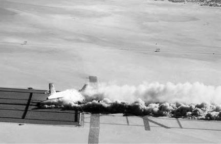
On December 1, 1984, a Boeing 720B airliner crashed near the east shore of Rogers Dry Lake. Although none of the 73 passengers walked away from the flaming wreckage, there were no fatalities. The occu­pants were plastic, anthropomorphic dummies, some of them instrumented to collect research data. There was no flight crew on board; the pilot was seated in a ground-based cockpit 6 miles away at NASA Dryden.

As early as 1980, Federal Aviation Administration (FAA) and NASA officials had been planning a full-scale transport aircraft crash dem­onstration to study impact dynamics and new safety technologies to improve aircraft crashworthiness. Initially dubbed the Transport Crash Test, the project was later renamed Transport Aircraft Remotely Piloted Ground Impact Test (TARGIT). In August 1983, planners set­tled on the name Controlled Impact Demonstration (CID). Some wags immediately twisted the acronym to stand for "Crash in the Desert” or "Cremating Innocent Dummies.”[954] In point of fact, no fireball was expected. One of the primary test objectives included demonstration of anti-misting kerosene (AMK) fuel, which was designed to prevent for­mation of a postimpact fireball. While many airplane crashes are surviv – able, most victims perish in postcrash fire resulting from the release of fuel from shattered tanks in the wings and fuselage. In 1977, FAA offi­cials looked into the possibility of using an additive called Avgard FM-9 to reduce the volatility of kerosene fuel released during catastrophic crash events. Ground-impact studies using surplus Lockheed SP-2H airplanes

showed great promise, because the FM-9 prevented the kerosene from forming a highly volatile mist as the airframe broke apart.[955] As a result of these early successes, the FAA planned to implement the require­ment that airlines add FM-9 to their fuel. Estimates made calculated that the impact of adopting AMK would have included a one-time cost to airlines of $25,000-$35,000 for retrofitting each high-bypass turbine engine and a 3- to 6-percent increase in fuel costs, which would drive ticket prices up by $2-$4 each. In order to definitively prove the effective­ness of AMK, officials from the FAA and NASA signed a Memorandum of Agreement in 1980 for a full-scale impact demonstration. The FAA was responsible for program management and providing a test aircraft, while NASA scientists designed the experiments, provided instrumen­tation, arranged for data retrieval, and integrated systems.[956] The FAA supplied the Boeing 720B, a typical intermediate-range passenger trans­port that entered airline service in the mid-1960s. It was selected for the test because its construction and design features were common to most contemporary U. S. and foreign airliners. It was powered by four Pratt & Whitney JT3C-7 turbine engines and carried 12,000 gallons of fuel. With a length of 136 feet, a 130-foot wingspan, and maximum takeoff weight of 202,000 pounds, it was the world’s largest RPRV. FAA Program Manager John Reed headed overall CID project development and coor­dination with all participating researchers and support organizations.

Researchers at NASA Langley were responsible for characteriz­ing airframe structural loads during impact and developing a data – acquisition system for the entire aircraft. Impact forces during the demonstration were characterized as being survivable for planning purposes, with the primary danger to be from postimpact fire. Study data to be gathered included measurements of structural, seat, and occu­pant response to impact loads, to corroborate analytical models devel­oped at Langley, as well as data to be used in developing a crashworthy seat and restraint system. Robert J. Hayduk managed NASA crashwor­thiness and cabin-instrumentation requirements.[957] Dryden personnel,

under the direction of Marvin R. "Russ” Barber, were responsible for overall flight research management, systems integration, and flight operations. These included RPRV control and simulation, aircraft/ground interface, test and systems hardware integration, impact-site preparation, and flight-test operations.

The Boeing 720B was equipped to receive uplinked commands from the ground cockpit. Commands providing direct flight path control were routed through the autopilot, while other functions were fed directly to appropriate systems. Information on engine performance, navigation, attitude, altitude, and airspeed was downlinked to the ground pilot.[958] Commands from the ground cockpit were conditioned in control-law computers, encoded, and transmitted to the aircraft from either a pri­mary or backup antenna. Two antennas on the top and bottom of the Boeing 720B provided omnidirectional telemetry coverage, each feeding a separate receiver. The output from the two receivers was then combined into a single input to a decoder that processed uplink data and generated commands to the controls. Additionally, the flight engineer could select redundant uplink transmission antennas at the ground station. There were three pulse-code modulation systems for downlink telemetry, two for exper­imental data, and one to provide aircraft control and performance data.

The airplane was equipped with two forward-facing television cam­eras—a primary color system and a black-and-white backup—to give the ground pilot sufficient visibility for situational awareness. Ten high­speed motion picture cameras photographed the interior of the pas­senger cabin to provide researchers with footage of seat and occupant motion during the impact sequence.[959] Prior to the final CID mission, 14 test flights were made with a safety crew on board. During these flights, 10 remote takeoffs, 13 remote landings (the initial landing was made by the safety pilot), and 69 CID approaches were accomplished. All remote takeoffs were flown from the Edwards Air Force Base main runway. Remote landings took place on the emergency recovery run­way (lakebed Runway 25).

Research pilots for the project included Edward T. Schneider, Fitzhugh L. Fulton, Thomas C. McMurtry, and Donald L. Mallick.

William R. "Ray” Young, Victor W. Horton, and Dale Dennis served as flight engineers. The first flight, a functional checkout, took place March 7, 1984. Schneider served as ground pilot for the first three flights, while two of the other pilots and one or two engineers acted as safety crew. These missions allowed researchers to test the uplink/downlink systems and autopilot, as well as to conduct airspeed calibration and collect ground-effects data. Fulton took over as ground pilot for the remain­ing flight tests, practicing the CID flight profile while researchers qual­ified the AMK system (the fire retardant AMK had to pass through a degrader to convert it into a form that could be burned by the engines) and tested data-acquisition equipment. The final pre-CID flight was com­pleted November 26. The stage was set for the controlled impact test.[960] The CID crash scenario called for a symmetric impact prior to encoun­tering obstructions as if the airliner were involved in a gear-up landing short of the runway or an aborted takeoff. The remote pilot was to slide the airplane through a corridor of heavy steel structures designed to slice open the wings, spilling fuel at a rate of 20 to 100 gallons per second. A specially prepared surface consisting of a rectangular grid of crushed rock peppered with powered electric landing lights provided ignition sources on the ground, while two jet-fueled flame generators in the air­plane’s tail cone provided onboard ignition sources.

On December 1, 1984, the Boeing 720B was prepared for its final flight. The airplane had a gross takeoff weight of 200,455 pounds, including 76,058 gallons of AMK fuel. Fitz Fulton initiated takeoff from the remote cockpit and guided the Boeing 720B into the sky for the last time.[961]At an altitude of 200 feet, Fulton lined up on final approach to the impact site. He noticed that the airplane had begun to drift to the right of centerline but not enough to warrant a missed approach. At 150 feet, now fully commit­ted to touchdown because of activation of limited-duration photographic and data-collection systems, he attempted to center the flight path with a left aileron input, which resulted in a lateral oscillation.

The Boeing 720B struck the ground 285 feet short of the planned impact point, with the left outboard engine contacting the ground first.

On TARGIT: Civil Aviation Crash Testing in the

NASA and the FAA conducted a Controlled Impact Demonstration with a remotely piloted Boeing 720 aircraft. NASA.


9


This caused the airplane to yaw during the slide, bringing the right inboard engine into contact with one of the wing openers and releasing large quantities of degraded (i. e., highly flammable) AMK and exposing them to a high-temperature ignition source. Other obstructions sliced into the fuselage, permitting fuel to enter beneath the passenger cabin. The resulting fireball was spectacular.[962]

To casual observers, this might have made the CID project appear a failure, but such was not the case. The conditions prescribed for the AMK test were very narrow and failed to account for a wide range of variables, some of which were illustrated during the flight test. The results were sufficient to cause FAA officials to abandon the idea of forc­ing U. S. airlines to use AMK, but the CID provided researchers with a wide range of data for improving transport-aircraft crash survivability.

The experiment also provided significant information for improv­ing RPV technology. The 14 test flights leading up to the final demon­stration gave researchers an opportunity to verify analytical models, simulation techniques, RPV control laws, support software, and hard­ware. The remote pilot assessed the airplane’s handling qualities, allowing
programmers to update the simulation software and validate the con­trol laws. All onboard systems were thoroughly tested, including AMK degraders, autopilot, brakes, landing gear, nose wheel steering, and instrumentation systems. The CID team also practiced emergency pro­cedures, such as the ability to abort the test and land on a lakebed run­way under remote control, and conducted partial testing of an uplinked flight termination system to be used in the event that control of the air­plane was lost. Several anomalies—intermittent loss of uplink signal, brief interruption of autopilot command inputs, and failure of the uplink decoder to pass commands—cropped up during these tests. Modifications were implanted, and the anomalies never recurred.[963] Handling qualities were generally good. The ground pilot found landings to be a special challenge as a result of poor depth perception (because of the low- resolution television monitor) and lack of peripheral vision. Through flight tests, the pilot quickly learned that the CID profile was a high – workload task. Part of this was due to the fact that the tracking radar used in the guidance system lacked sufficient accuracy to meet the impact parameters. To compensate, several attempts were made to improve the ground pilot’s performance. These included changing the flight path to give the pilot more time to align his final trajectory, improving ground markings at the impact site, turning on the runway lights on the test sur­face, and providing a frangible 8-foot-high target as a vertical reference on the centerline. All of these attempts were compromised to some degree by the low-resolution video monitor. After the impact flight, members of the control design team agreed that some form of head-up display (HUD) would have been helpful and that more of the piloting tasks should have been automated to alleviate pilot workload.[964] In terms of RPRV research, the project was considered highly successful. The remote pilots accu­mulated 16 hours and 22 minutes of RPV experience in preparation for the impact mission, and the CID showed the value of comparing pre­dicted results with flight-test data. U. S. Representative William Carney, ranking minority member of the House Transportation, Aviation, and Materials Subcommittee, observed the CID test. "To those who were disappointed with the outcome,” he later wrote, "I can only say that the
results dramatically illustrated why the tests were necessary. I hope we never lose sight of the fact that the first objective of a research program is to learn, and failure to predict the outcome of an experiment should be viewed as an opportunity, not a failure.”[965]

Civilian Supersonic Cruise: The National SST Effort

The fascination for higher speeds of the 1950s and the new long-range comfortable jet airliners combined to create an interest in a supersonic airliner. The dominance of American aircraft manufacturers designs in the long-range subsonic jet airliner market meant that European man­ufacturers turned their sights on that goal. As early as 1959, when jet traffic was just commencing, Sir Peter Masefield, an influential avia­tion figure, said that a supersonic airliner should be a national goal for Britain. Development of such an airplane would contribute to national
prestige, enhance the national technology skill level, and contribute to a favorable trade balance by foreign sales. He recognized that the under­taking would be expensive and that the government would have to sup­port the development of the aircraft. The possibility was also suggested of a cooperative design effort with the United States. Meanwhile, the French aviation industry was pursuing a similar course. Eventually, in 1962, Britain and France merged their efforts to produce a joint European aircraft cruising at Mach 2.2.16

Подпись: 10A Supersonic Transport had also been envisioned in the United States, and low-level studies had been initiated at NACA Langley in 1956, headed by John Stack. But the European initiatives triggered an intensification of American efforts, for essentially the same reasons listed by Masefield. In 1960, Convair proposed a new 52-seat modified-fuselage version of its Mach 2 B-58, preceded by a testbed B-58 with 5 intrepid volunteers in airline seats in the belly pod (windows and a life-support system were to be installed).[1070] The influential magazine Aviation Week reflected the tenor of the American feeling by proposing that the United States make SST a national priority, akin to the response to Sputnik.[1071] Articles appeared outlining the technology for supersonic cruise speeds up to Mach 4 with existing technology. The USAF’s Wright Air Development Division con­vened a conference in late 1960 to discuss the SST for military as well as civilian use.[1072] And in 1961, the newly created Federal Aviation Agency (FAA) began to work with the newly created NASA and the Air Force in Project Horizon to study an American SST program. One of the big questions was whether the design cruise speed should be Mach 2, as the Europeans were striving for, or closer to Mach 3.[1073]

Подпись: 10 Civilian Supersonic Cruise: The National SST Effort

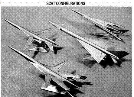
Both Langley and Ames had been engaged in large supersonic air­craft design studies for years and had provided technical support for the Air Force WS-110 program that became the Mach 3 cruise B-70.[1074] Langley had also pioneered work on variable-sweep wings, in part draw­ing upon variable wing sweep technology as explored by the Bell X-5 in NACA testing, to solve the problem of approach speeds for heavy air­planes with highly swept wings for supersonic cruise but also required to operate from existing jet runways. Langley embarked upon develop­ing baseline configurations for a theoretical Supersonic Commercial Air Transport (SCAT), with Ames also participating. Clinton Brown and

F. Edward McLean at Langley developed the so-called arrow wing, with highly swept leading and trailing edges, that promised to produce higher L/D at supersonic cruise speeds. In June 1963, the theoretical research
became more developmental, as President John F. Kennedy announced that the United States would build an SST with Government funding of up to $1 billion provided to industry to aid in the development.

Подпись: 10In September 1963, NASA Langley hosted a conference for the air­craft industry presenting independent detailed analyses by Boeing and Lockheed of four NASA-developed configurations known as SCAT 4 (arrow wing), 15 (arrow wing with variable sweep), 16 (variable sweep), and 17 (delta with canard). Langley research had produced the first three, and Ames had produced SCAT 17.[1075] Additionally, papers on NASA research on SST technology were presented. The detailed analyses by both contractors of the baselines concluded that a supersonic transport was technologically feasible, and that the specified maximum range of 3,200 nautical miles would be possible at Mach 3 but not at Mach 2.2. The economic feasibility of an SST was not evaluated directly, although each contractor commented on operating cost comparisons with the Boeing 707. Although the initial FAA SST specification called for Mach 2.2 cruise, the conference baseline was Mach 3, with one of the configu­rations also being evaluated at Mach 2.2. The results and the need to make the American SST more attractive to airlines than the European Concorde shifted the SST baseline to a Mach 2.7 to Mach 3 cruise speed. This speed was similar to that of the XB-70, so the results of its test program could be directly applicable to development of an SST. As the 1963 conference report stated, "Significant research will be required in the areas of aero­dynamic performance, handling qualities, sonic boom, propulsion, and structural fabrication before the supersonic transport will be a success.”[1076]

JSC, the FAA, and Targets of Opportunity

Подпись: 11As 2005 drew to a close, Michael Coffman at FAA Oklahoma City had convinced his line management that a flight demonstration of the sen­sor fusion technology would be a fine precursor to further FAA interest. FAA Oklahoma City had a problem: how best to protect its approaches of flight-check aircraft certifying instruments for the Department of Defense in combat zones. Coffman and Fox had suggested sensor fusion. If onboard video sensors in a flight-check aircraft could image a termi­nal approach corridor with a partially blended synthetic approach cor­ridor, any obstacle penetrating the synthetic corridor could be quickly identified. Coffman, using the MOU with NASA JSC signed just that July, suggested that an FAA Challenger 604 flight-check aircraft based at FAA Oklahoma City could be configured with SVS equipment to dem­onstrate the technology to NASA and FAA managers. Immediately, Fox, Coffman, Mike Abernathy of RIS, Patrick Laport and Tim Verborgh of AANA, and JSC electronics technician James Secor began discussing how to configure the Challenger 604. Fox tested his ability to scrounge excess material from JSC by acquiring an additional obsolete but ser­viceable Embedded GPS Inertial Navigation System (EGI) navigation processor (identical to the one used in the ACES van) and several pro­cessors to drive three video displays. Coffman found some FAA funds to buy three monitors, and Abernathy and RIS wrote the software nec­essary to drive three monitors with SVS displays with full-sensor fusion capability, while Laport and Verborgh developed the symbology set for the displays. The FAA bought three lipstick cameras, JSC’s Jay Estes designed a pallet to contain the EGI and processors, and a rudimentary portable system began to take shape.[1192]

The author, now a research pilot at the Johnson Space Center, became involved assisting AANA with the design of a notional instrument pro­cedure corridor at JSC’s Ellington Field flight operations base. He also obtained permission from his management chain to use JSC’s Aircraft

Operations Division to host the FAAs Challenger and provide the jet fuel it required. Verborgh, meanwhile, surveyed a number of locations on Ellington Field with the author’s help, using a borrowed portable DGPS system to create by hand a synthetic database of Ellington Field, the group not having access to expensive commercial databases. The author and JSC’s Donald Reed coordinated the flight operations and air traffic control approvals, Fox and Coffman handled the interagency approv­als, and by March 2006, the FAA Challenger 604 was at Ellington Field with the required instrumentation installed and ready for the first sen­sor fusion-guided instrument approach demonstration. Fox had bor­rowed helmet-mounted display hardware and a kneeboard computer to display selected sensor fusion scenes in the cabin, and five demonstra­tion flights were completed for over a dozen JSC Shuttle, Flight Crew Operations, and Constellation managers. In May, the flights were com­pleted to the FAA’s satisfaction. The sensor fusion software and hardware performed flawlessly, and both JSC and FAA Oklahoma City manage­ment gained confidence in the team’s capabilities, a confidence that would continue to pay dividends. For its part, JSC could not afford a more extensive, focused program, nor were Center managers uniformly convinced of the applicability of this technology to their missions. The team, however, had greatly bolstered confidence in its ability to accom­plish critically significant flight tests, demonstrating that it could do so with "shoestring” resources and support. It did so by using a small-team approach, building strong interagency partnerships, creating relation­ships with other research organizations and small businesses, relying on trust in one another’s professional abilities, and following rigorous adherence to appropriate multiagency safety reviews.

Подпись: 11The success of the approach demonstrations allowed the team mem­bers to continue with the SVS work on a not-to-interfere basis with their regularly assigned duties. Fox persuaded his management to allow the ACES van to remotely control the JSC Scout simulated lunar rover on three trips to Meteor Crater, AZ, in 2005-2006 using the same sensor fusion software implementation as that on the Challenger flight test. Throughout the remainder of 2006, the team discussed other possibil­ities to demonstrate its system. Abernathy provided the author with a kneeboard computer, a GPS receiver, and the RIS’s LandForm software (for which JSC had rights) with a compressed, high-resolution database of the Houston area. On NASA T-38 training flights, the author evaluated the performance of the all-aspect software in anticipation of an official

Подпись: 11 JSC, the FAA, and Targets of Opportunity

evaluation as part of a potential T-38 fleet upgrade. The author had con­versations with Coffman, Fox, and Abernathy regarding the FAA’s idea of using a turret on flight-check aircraft to measure in real time the height of approach corridor obstacles. The conservations and the portability of the software and hardware inspired the author to suggest a flight test using one of JSC’s WB-57F High-Altitude Research Airplanes with the WB-57F Acquisition Validation Experiment (WAVE) sensor as a proof of concept. The WB-57F was a JSC high-altitude research airplane capable of extended flight above 60,000 feet with sensor payloads of thousands of pounds and dozens of simultaneous experiments. The WAVE was a sophis­ticated, 360-degree slewable camera tracking system developed after the Columbia accident to track Space Shuttle launches and reentries.[1193]

The author flew the WB-57F at JSC, including WAVE Shuttle tracking missions. Though hardly the optimal airframe (the sensor fusion proof of concept would be flown at only 2,000 feet altitude), the combination of a JSC airplane with a slewable, INS/GPS-supported camera system was hard to beat. The challenges were many. The two WB-57F airframes at JSC were scheduled years in advance, they were expensive for a single
experiment when designed to share costs among up to 40 simultaneous experiments, and the WAVE sensor was maintained by Southern Research Institute (SRI) in Birmingham, AL. Fortunately, Mike Abernathy of RIS spoke directly to John Wiseman of SRI, and an agreement was reached in which SRI would integrate RIS’s LandForm software into WAVE for no cost if it were allowed to use it for other potential WAVE projects.

Подпись: 11The team sought FAA funding on the order of $30,000-$40,000 to pay for the WB-57F operation and integration costs and transport the WAVE sensor from Birmingham to Houston. In January 2007, the team invited Frederic Anderson—Manager of Aero-Nav Services at FAA Oklahoma City—to visit JSC to examine the ACES van, meet with the WB-57F Program Office and NASA Exploration Program officials, and receive a demonstration of the sensor fusion capabilities. Anderson was convinced of the potential of using the WB-57/WAVE to prove that an object on the ground could be passively, remotely measured in real time to high accuracy. He was willing to commit $40,000 of FAA money to this idea. With one challenge met, the next challenge was to find a hole in the WB-57F’s schedule.

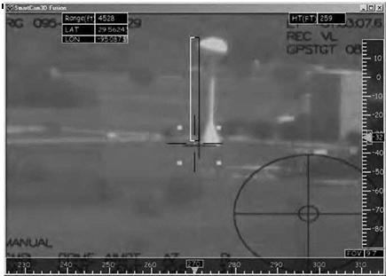
In mid-March 2007, the author was notified that a WB-57F would be available the first week in April. In 3 weeks Fox, pushed through a Space Act Agreement to get FAA Oklahoma City funds transferred to JSC, with pivotal help from the JSC Legal Office. RIS and AANA, work­ing nonstop with SRI, integrated the sensor fusion software into the WAVE computers. Due to a schedule slip with the WB-57, the team only had a day and a half to integrate the RIS hardware into the WB-57, with the invaluable help of WB-57 engineers. Finally, on April 6, on a 45-minute flight from Ellington Field, the author and WAVE operator Dominic Del Rosso of JSC for the first time measured an object on the ground (the JSC water tower) in flight in real time using SVS technol­ogy. The video signal from the WAVE acquisition camera was blended with synthetic imagery to provide precise scaling.

The in-flight measurement was within 0.5 percent of the surveyed data. The ramifications of this accomplishment were immediate and profound: the FAA was convinced of the power of the SVS sensor fusion technology and began incorporating the capability into its planned flight-check fleet upgrade.[1194]

Подпись: 11 JSC, the FAA, and Targets of Opportunity

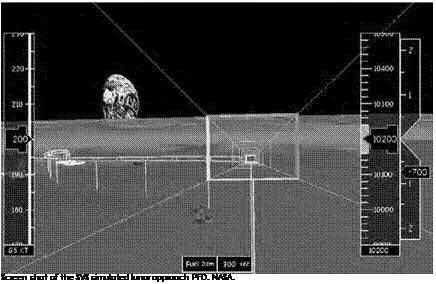
Building on this success, Fox, Coffman, Abernathy, and the author looked at new ways to showcase sensor fusion. In the back of their minds had been the concept of simulating a lunar approach into a vir­tual lunar base anchored over Ellington Field. The thought was to use the FAA Challenger 604 with the SVS portable pallet installed as before. The problem was money. A solution came from a collaboration between the author and his partner in a NASA JSC aircraft fleet upgrade study, astronaut Joseph Tanner. They had extra money from their fleet study budget, and Tanner was intrigued by the proposed lunar approach sim­ulation because it related to a possible future lunar approach training aircraft. The two approached Brent Jett, who was Director of Flight Crew Operations and the sponsor of their study, in addition to oversee­ing the astronauts and flight operations at JSC. Jett was impressed with the idea and approved the necessary funds to pay the operational cost of the Challenger 604. FAA Oklahoma City would provide the airplane and crew at its expense.

Once again, RIS and AANA on their own modified the software to simulate a notional lunar approach designed by the author and Fox, derived from the performance of the Challenger 604 aircraft. Coffman was able to retrieve the monitors and cameras from the approach
flight tests of 2006. Jim Secor spent a day at FAA Oklahoma City rein­stalling the SVS pallet and performing the necessary integration with Michael Coffman. The author worked with Houston Approach Control to gain approval for this simulated lunar approach with a relatively steep flightpath into Ellington Field and within the Houston Class B (Terminal Control Area) airspace. The trajectory commenced at 20,000 feet, with a steep power-off dive to 10,000 feet, at which point a 45-degree course correction maneuver was executed. The approach terminated at 2,500 feet at a simulated 150-feet altitude over a virtual lunar base anchored overhead Ellington Field. Because there was no digital database avail­able for any of the actual proposed lunar landing sites, the team used a modified database for Meteor Crater as a simulated lunar site. The team switched the coordinates to Ellington Field so that the EGI could still provide precise GPS navigation to the virtual landing site anchored overhead the airport.

Подпись: 11

Подпись: Screen shot of the SVS simulated lunar approach PFD. NASA.

In early February 2008, all was ready. The ACES van was used to val­idate the model as there was no time (or money) to do it on the airplane. One instrumentation checkout flight was flown, and several anomalies were corrected. That afternoon, for the first time, an aircraft was used to simulate a lunar approach to a notional lunar base. Sensor fusion was demonstrated on one of the monitors using the actual ambient conditions to provide Sun glare and haze challenges. These were not

representative of actual lunar issues but were indicative of the benefit of sensor fusion to mitigate the postulated 1-degree Sun angles of the south lunar pole. The second monitor showed the SVS Meteor Crater digital terrain database simulating the lunar surface and perfectly matched to the Houston landscape over which the Challenger 604 was flying.[1195] This and two more flights demonstrated the technology to a dozen astronauts and to Constellation and Orion program managers.

Подпись: 11Four flight test experiments and three trips to Meteor Crater were completed in a 3-year period to demonstrate the SVS sensor fusion tech­nology. The United States military is using evolved versions of the orig­inal X-38 SVS and follow-on sensor fusion software with surveillance sensors on various platforms, and the FAA has contracted with RIS to develop an SVS for its flight-check fleet. Constellation managers have shown much interest in the technology, but by 2009, no decision has been reached regarding its incorporation in NASA’s space exploration plans.[1196]

Partners on Ice

Подпись: 12As it is with other areas involving aviation, NASA’s role in aircraft icing is as a leader in research and technology, leaving matters of regulations and certifications to the FAA. Often the FAA comes to NASA with an idea or a need, and the Agency then takes hold of it to make it happen. Both the National Center for Atmospheric Research and NOAA have actively partnered with NASA on icing-related projects. NASA also is a major player in the Aircraft Icing Research Alliance (AIRA), an interna­tional partnership that includes NASA, Environment Canada, Transport Canada, the National Research Council of Canada, the FAA, NOAA, the National Defense of Canada, and the Defence Science and Technology Laboratory (DSTL)-United Kingdom. AIRAs primary research goals com­plement NASA’s, and they are to

• Develop and maintain an integrated aircraft icing research strategic plan that balances short-term and long-term research needs,

• Implement an integrated aircraft icing research strate­gic plan through research collaboration among the AIRA members,

• Strengthen and foster long-term aircraft icing research expertise,

• Exchange appropriate technical and scientific information,

• Encourage the development of critical aircraft icing tech­nologies, and

• Provide a framework for collaboration between AIRA members.

Finally, among the projects NASA is working with AIRA members includes the topics of ground icing, icing for rotorcraft, characteriza­tion of the atmospheric icing environment, high ice water content, icing cloud instrumentation, icing environment remote sensing, propulsion system icing, and ice adhesion/shedding from rotating surfaces—the last two a reference to the internal engine icing problem that is likely to make icing headlines during the next few years.

Подпись: 12The NACA-NASA role in the history of icing research, and in search­ing for means to frustrate this insidious threat to aviation safety, has been one of constant endeavor, constantly matching the growth of scientific understanding and technical capabilities to the threat as it has evolved over time. From crude attempts to apply mechanical fixes, fluids, and heating, NACA and NASA researchers have advanced to sophisticated modeling and techniques matching the advances of aerospace science in the fields of fluid mechanics, atmospheric physics, and computer analysis and simulation. Through all of that, they have demonstrated another constant as well: a persistent dedication to fulfill a mandate of Federal aeronautical research dating to the founding of the NACA itself and well encapsulated in its founding purpose: "to supervise and direct the scientific study of the problems of flight, with a view to their prac­tical solution.”

A drop model of the F/A-1 8E is released for a poststall study high above the NASA Wallops Flight Center. NASA.


Partners on Ice

Opportunities

After the results of the NASA HATP project in 1996 and the F/A-18E/F wing-drop and AWS programs were disseminated, it was widely recog­nized that computational fluid dynamics had tremendous potential as an additional tool in the designer’s toolkit for high-angle-of-attack flight conditions. However, it was also appreciated that the complexity of the physics of flow separation, the enormous computational resources required for accurate predictions, and the fundamental issues regarding representation of key characteristics such as turbulence would be for­midable barriers to progress. Even more important, the lack of commu­nication between the experimental test and evaluation community and the CFD community was apparent. More specifically, the T&E commu­nity placed its trust in design methods it routinely used for high-angle – of-attack analysis—namely, the wind tunnel and experimental methods. Furthermore, a majority of the T&E engineers were not willing to accept what they regarded as an aggressive "oversell” of CFD capabilities with­out many examples that the computer could reliably predict aircraft stability and control parameters at high angles of attack. Meanwhile, the CFD community had continued its focus on applications related to aircraft performance, with little or no awareness of the aerodynamic
problems faced by the T&E community for high-angle-of-attack pre­dictions. One example of the different cultures of the communities was that a typical CFD expert was used to striving for accuracies within a few percent for performance-related estimates, whereas the T&E ana­lyst was, in many cases, elated to know simply whether parameters at high angles of attack were positive or negative.

Подпись: 13Stimulated to bring these two groups together for discussions, Langley conceived a plan for a project known as Computational Methods for Stability and Control (COMSAC), which could poten­tially spin off focused joint programs to assess, modify, and calibrate computational codes for the prediction of critical aircraft stability and control parameters for high-angle-of-attack conditions.[1328] Many envi­sioned the start of another HATP-like effort, with similar outlooks for success. In 2004, Langley hosted a COMSAC Workshop, which was well – attended by representatives of the military and civil aviation industries, DOD, and academia. As expected, controversy was widespread regard­ing the probability of success in applying CFD to high-angle-of-attack stability and control predictions. Stability and control attendees expressed their "show me that it works” philosophy regarding CFD, while the CFD experts were alarmed by the complexity of typical exper­imental aerodynamic data for high-angle-of-attack flight conditions. Nonetheless, the main objective of establishing communications between the two scientific communities was accomplished, and NASA’s follow-on plans for establishing research efforts in this area were eagerly awaited.

Unfortunately, changes in NASA priorities and funding distribu­tions terminated the COMSAC planning activity after the workshop. However, several attendees returned to their organizations to initiate CFD studies to evaluate the ability of existing computer codes to pre­dict stability and control at high angles of attack. Experts at the Naval Air Systems Command have had notable success using the F/A-18E as a test configuration.[1329]

Despite the inability to generate a sustainable NASA research effort to advance the powerful CFD methods for stability and control, the COMSAC experience did inspire other organizations to venture into the area. It appears that such an effort is urgently needed, especially in view of the shortcomings in the design process.

HSR and the Genesis of the Tu-144 Flight Experiments

NASA’s High-Speed Research program was initiated in 1990 to investi­gate a number of technical challenges involved with developing a Mach 2+ High-Speed Civil Transport (HSCT). This followed several years of NASA-sponsored studies in response to a White House Office of Science and Technology Policy call for research into promoting long-range, high­speed aircraft. The speed spectrum for these initial studies spanned the supersonic to transatmospheric regions, and the areas of interest included economic, environmental, and technical considerations. The studies suggested a viable speed for a proposed aircraft in the Mach 2 to Mach 3.2 range, and this led to the conceptual model for the HSR pro­gram. The initial goal was to determine if major environmental obsta­cles—including ozone depletion, community noise, and sonic boom generation—could be overcome. NASA selected the Langley Research Center in Hampton, VA, to lead the effort, but all NASA aeronautics Centers became deeply involved in this enormous program. During this

Phase I period, NASA and its industry partners determined that the state of the art in high-speed design would allow mitigation of the ozone and noise issues, but sonic boom alleviation remained a daunting challenge.[1460]

Подпись: 15Encouraged by these assessments, NASA began Phase II of the HSR program in 1995 in partnership with Boeing Commercial Airplane Group, McDonnell-Douglas Aerospace, Rockwell North American Aircraft Division, General Electric Aircraft Engines, and Pratt & Whitney. By this time, a baseline concept had emerged for a Mach 2.4 aircraft, known as the Reference H model and capable of carrying 300 passengers non­stop across the Pacific Ocean. A comprehensive list of technical issues was slated for investigation, including sonic boom effects, ozone deple­tion, aeroacoustics and community noise, airframe/propulsion integra­tion, high lift, and flight deck design. Of high interest to NASA Langley Research Center engineers was the concept of Supersonic Laminar Flow Control (SLFC). Maintaining laminar flow of the supersonic airstream across the wing surface for as long as possible would lead to much higher cruise efficiencies. NASA Langley investigated SLFC using wind tunnel, computational fluid dynamics, and flight-test experiments, including the use of NASA’s two F-16XL research aircraft flown at NASA Langley and NASA Dryden Flight Research Centers. Unfortunately, the relatively small size of the unique, swept wing F-16XL led to contamination of the laminar flow by shock waves emanating from the nose and canopy of the aircraft. Clearly, a larger airplane was needed.[1461]

That larger airplane seemed more and more likely to be the Tupolev Tu-144 as proposals devolved from a number of disparate sources, and a variety of serendipitous circumstances aligned in the early 1990s to make that a reality. Aware of the HSR program, the Tupolev Aircraft Design Bureau as early as 1990 proposed a Tu-144 as a flying laboratory for supersonic research. In 1992, NASA Langley’s Dennis Bushnell discussed with Tupolev this possibility of returning to flight one of the few remain­ing Tu-144 SSTs as a supersonic research aircraft. Pursuing Bushnell’s ini­tial inquiries, Joseph R. Chambers, Chief of Langley’s Flight Applications Division, and Kenneth Szalai, NASA’s Dryden Flight Research Center

Подпись: 15Director, developed a formal proposal for NASA Headquarters sug­gesting the use of a Tu-144 for SLFC research. Szalai discussed this idea with his friend Lou Williams, of the HSR Program Office at NASA Headquarters, who became very interested in the Tu-144 concept. NASA Headquarters had, in the meantime, already been considering using a Tu-144 for HSR research and had contracted Rockwell North American Aircraft Division to conduct a feasibility study. NASA and Tupolev officials, including Ken Szalai, Lou Williams, and Tupolev chief engineer Alexander Pukhov, first directly discussed the details of a joint program at the Paris Air Show in 1993, after Szalai and Williams had requested to meet with Tupolev officials the previous day.[1462] The synergistic force ultimately uniting all of this varied interest was the 1993 U. S.-Russian Joint Commission on Economic and Technological Cooperation. Looking at peaceful means of technological cooperation in the wake of the Cold War, the two former adversaries now pur­sued programs of mutual interest. Spurred by the Commission, NASA, industry, and Tupolev managers and researchers evaluated the potential benefits of a joint flight experiment with a refurbished Tu-144 and developed a prioritized list of potential experiments. With positive responses from NASA and Tupolev, a cooperative Tu-144 flight research project was initiated and an agreement signed in 1994 in Vancouver, Canada, between Russian Prime Minister Viktor Chernomyrdin and Vice President Al Gore. Ironically, Langley’s interest in SLFC was not included in the list of experiments to be addressed in this largest joint aeronautics research project between the two former adversaries.[1463] Ultimately, seven flight experiments were funded and accomplished by NASA, Tupolev, and Boeing personnel (Boeing acquired McDonnell – Douglas and Rockwell’s aerospace division in December 1996). Overcoming large distances, language and political barriers, cultural differences, and even different approaches to technical and engineer­ing problems, these dedicated researchers, test pilots, and technicians accomplished 27 successful test flights in 2 years.

Avionics

Lightning effects on avionics can be disastrous, as illustrated by the account of the loss of AC-67. Composite aircraft with internal radio anten­nas require fiberglass composite "windows” in the lightning-strike mesh near the antenna. (Fiberglass composites are employed because of their transparency to radio frequencies, unlike carbon fiber.) Lightning pro­tection and avoidance are important for planning and conducting flight tests. Consequently, NASA’s development of lightning warning and detec­tion systems has been a priority in furthering fly-by-wire (FBW) systems. Early digital computers in flight control systems encountered conditions in which their processors could be adversely affected by lightning-generated electrical pulses. Subsequently, design processes were developed to pro­tect electronic equipment from lightning strikes. As a study by the North Atlantic Treaty Organization (NATO) noted, such protection is "particu­larly important on aircraft with composite structures. Although equipment bench tests can be used to demonstrate equipment resistance to lightning strikes and EMP, it is now often considered necessary to perform whole aircraft lightning-strike tests to validate the design and clearance process.”[173]

Celeste M. Belcastro of Langley contrasted laboratory, ground-based, and in-flight testing of electromagnetic environmental effects, noting:

Laboratory tests are primarily open-loop and static at a few operating points over the performance envelope of the equipment and do not consider system level effects. Full-aircraft tests are also static with the aircraft situated on the ground and equipment powered on during expo­sure to electromagnetic energy. These tests do not pro­vide a means of validating system performance over the operating envelope or under various flight conditions. . . .

The assessment process is a combination of analysis, sim­ulation, and tests and is currently under development for demonstration at the NASA Langley Research Center. The assessment process is comprehensive in that it addresses (i) closed-loop operation of the controller under test, (ii) real-time dynamic detection of controller malfunctions that occur due to the effects of electromagnetic distur­bances caused by lightning, HIRF, and electromagnetic interference and incompatibilities, and (iii) the resulting effects on the aircraft relative to the stage of flight, flight conditions, and required operational performance.[174]

A prime example of full-system assessment is the F-16 Fighting Falcon, nicknamed "the electric jet,” because of its fly-by-wire flight con­trol system. Like any operational aircraft, F-16s have received lightning strikes, the effects of which demonstrate FCS durability. Anecdotal evi­dence within the F-16 community contains references to multiple light­ning strikes on multiple aircraft—as many as four at a time in close formation. In another instance, the leader of a two-plane section was struck, and the bolt leapt from his wing to the wingman’s canopy.

Aircraft are inherently sensor and weapons platforms, and so the lightning threat to external ordnance is serious and requires exami­nation. In 1977, the Air Force conducted tests on the susceptibility of AIM-9 missiles to lightning strikes. The main concern was whether the Sidewinders, mounted on wingtip rails, could attract strobes that could enter the airframe via the missiles. The evaluators concluded that the optical dome of the missile was vulnerable to simulated lightning strikes even at moderate currents. The AIM-9’s dome was shattered, and burn marks were left on the zinc-coated fiberglass housing. However, there was no evidence of internal arcing, and the test concluded that "it is unlikely that lightning will directly enter the F-16 via AIM-9 missiles.”[175] Quite clearly, lightning had the potential of damaging the sensitive optics and sensors of missiles, thus rendering an aircraft impotent. With the increasing digitization and integration of electronic engine controls, in addition to airframes and avionics, engine management systems are now a significant area for lightning resistance research.

National Aviation Operations Monitoring Service

A further contribution to the Aviation Safety Monitoring and Modeling project provided yet another method for gathering data and crunch­ing numbers in the name of making the Nation’s airspace safer amid increasingly crowded skies. Whereas the Aviation Safety Reporting System involved volunteered safety reports and the Performance Data Analysis and Reporting System took its input in real time from digital data sources, the National Aviation Operations Monitoring Service was a scientifically designed survey of the aviation community to generate statistically valid reports about the number and frequency of incidents that might compromise safety.[242]

After a survey was developed that would gather credible data from anonymous volunteers, an initial field trial of the NAOMS was held in 2000, followed by the launch of the program in 2001. Initially, the sur­veyors only sought out air carrier pilots who were randomly chosen from the FAA Airman’s Medical Database. Researchers characterized the response to the NAOMS survey as enthusiastic. Between April 2001 and December 2004, nearly 30,000 pilot interviews were completed, with a remarkable 83-percent return rate, before the project ran short of funds and had to stop. The level of response was enough to achieve statistical validity and prove that NAOMS could be used as a perma­nent tool for managers to assess the operational health of the ATC sys­tem and suggest changes before they were actually needed. Although NASA and the FAA desired for the project to continue, it was shut down on January 31, 2008.[243]

It’s worth mentioning that the NAOMS briefly became the sub­ject of public controversy in 2007, when NASA received a Freedom of Information Act request by a reporter for the data obtained in the NAOMS survey. NASA denied the request, using language that then NASA Administrator Mike Griffin said left an "unfortunate impression” that the Agency was not acting in the best interest of the public. NASA eventually released the data after ensuring the anonymity originally guaranteed to those who were surveyed. In a January 14, 2008, letter from Griffin to all NASA employees, the Administrator summed up the experience by writing: "As usual in such circumstances, there are les­sons to be learned, remembered, and applied. The NAOMS case dem­onstrates again, if such demonstrations were needed, the importance of peer review, scientific integrity, admitting mistakes when they are made, correcting them as best we can, and keeping our word, despite the crit­icism that can ensue.”[244]

The Science of Human Factors

To be clear, however, NASA did not invent the science of human factors. Not only has the term been in use long before NASA ever existed, the concept it describes has existed since the beginning of mankind. Human factors research encompasses nearly all aspects of science and technol­ogy and therefore has been described with several different names. In simplest terms, human factors studies the interface between humans and the machines they operate. One of the pioneers of this science, Dr. Alphonse Chapanis, provided a more inclusive and descriptive definition: "Human factors discovers and applies information about human behavior, abilities, limitations, and other characteristics to the design of tools, machines, systems, tasks, jobs, and environments for produc­tive, safe, comfortable, and effective human use.”[292] The goal of human factors research, therefore, is to reduce error, while increasing produc­tivity, safety, and comfort in the interaction between humans and the tools with which they work.[293]

As already suggested, the study of human factors involves a myriad of disciplines. These include medicine, physiology, applied psychology, engineering, sociology, anthropology, biology, and education.[294] These in turn interact with one another and with other technical and scientific fields, as they relate to behavior and usage of technology. Human factors issues are also described by many similar—though not necessarily syn­onymous—terms, such as human engineering, human factors engineer­ing, human factors integration, human systems integration, ergonomics, usability, engineering psychology, applied experimental psychology, bio­mechanics, biotechnology, man-machine design (or integration), and human-centered design.[295]

Automation Design

Automation technology is an important factor in helping aircrew mem­bers to perform more wide-ranging and complicated cockpit activities. NASA engineers and psychologists have long been actively engaged in developing automated cockpit displays and other technologies.[400] These will be essential to pilots in order for them to safely and effectively operate within a new air traffic system being developed by NASA and others, called Free Flight. This system will use technically advanced aircraft computer systems to reduce the need for air traffic controllers and allow pilots to choose their path and speed, while allowing the com­puters to ensure proper aircraft separation. It is anticipated that Free Flight will in the upcoming decades become incorporated into the Next Generation Air Transportation System.[401]