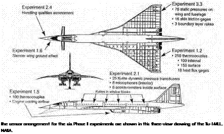
Short Take-Off and Landing flight research was primarily motivated by the desire of military and civil operators to develop transport aircraft with short-field operational capability typical of low-speed airplanes yet the high cruising speed of jets. For Langley and Ames, it was a natural extension of their earlier boundary layer control (BLC) activity undertaken in the 1950s to improve the safety and operational efficiency of military aircraft, such as naval jet fighters that had to land on aircraft carriers, by improving their low-speed controllability and reducing approach and landing speeds.[1338] Indeed, as NACA-NASA engineer-
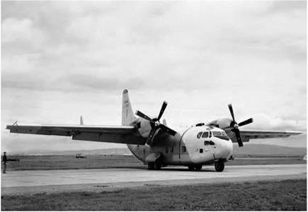
The Stroukoff YC-1 34A was the first large STOL research aircraft flown at NASA’s Ames Research Center. NASA.
historian Edwin Hartman wrote in 1970, "BLC was the first practical step toward achieving a V/STOL airplane.”[1339] This research had demonstrated the benefits of boundary layer flap-blowing, which eventually was applied to operational high-performance aircraft.[1340]
NASA’s first large-aircraft STOL flight research projects involved two Air Force-sponsored experimental transports: a Stroukoff Aircraft Corporation YC-134A and a Lockheed NC-130B Hercules. Both aircraft used boundary layer control over their flaps to augment wing lift.
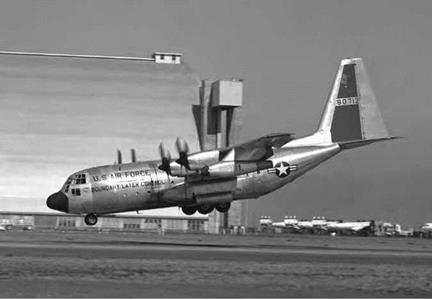
The NC-130B boundary layer control STOL testbed just before touchdown at Ames Research Center; note the wing-pod BLC air compressor, drooped aileron, and flap deflected 90 degrees. NASA.
The YC-134A was a twin-propeller radial-engine transport derived on the earlier Fairchild C-123 Provider tactical transport and designed in 1956. It had drooped ailerons and trailing-edge flaps that deflected 60 degrees, together with a strengthened landing gear. A J30 turbojet compressor provided suction for the BLC system. Tested between 1959 and mid-1961, the YC-134A confirmed expectations that deflected propeller thrust used to augment a wing’s aerodynamic lift could reduce stall speed. However, in other respects, its desired STOL performance was still limited, indicative of the further study needed at this time.[1341]
More promising was the later NC-130B, first evaluated in 1961 and then periodically afterward. Under an Air Force contract, the Georgia
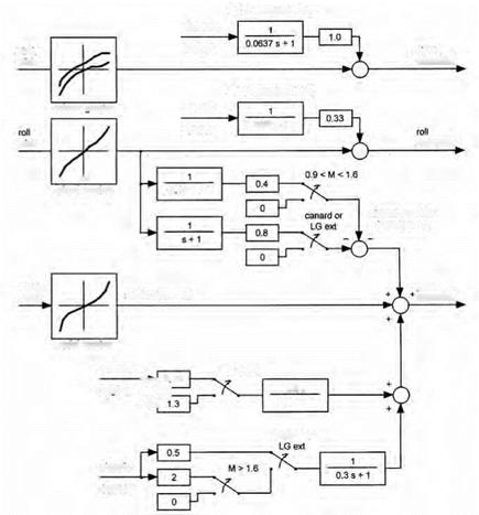
Division of Lockheed Aircraft Corporation modified a C-130B Hercules tactical transport to a STOL testbed. Redesignated as the NC-130B, it featured boundary layer blowing over its trailing-edge flaps (which could deflect a full 90 degrees down), ailerons (which were also drooped to enhance lift-generation), elevators, and rudder (which was enlarged to improve low-speed controllability). The NC-130 was powered by four Allison T-56-A-7 turbine engines, each producing 3,750 shaft horsepower and driving four-bladed 13.5-foot-diameter Hamilton Standard propellers. Two YT-56-A-6 engines driving compressors mounted in outboard wing-pods furnished the BLC air, at approximately 30 pounds of air per second at a maximum pressure ratio varying from 3 to 5. Roughly 75 percent of the air blew over the flaps and ailerons and 25 percent over the tail surfaces.[1342] Thanks to valves and crossover ducting, the BLC air could be supplied by either or both of the BLC engines. Extensive tests in Ames’s 40- by 80-foot wind tunnel validated the ability of the NC-130B’s BLC flaps to enhance lift at low airspeeds, but uncertainties remained regarding low-speed controllability. Subsequent flighttesting indicated that such concern was well founded. The NC-130B, like the YC-134A before it, had markedly poor lateral-directional control characteristics during low-speed approach and landing. Ames researchers used a ground simulator to devise control augmentation systems for the NC-130B. Flight test validated improved low-speed lateral – directional control.
 For a corresponding margin above the stall, the handling qualities of the NC-130B in the STOL configuration were changed quite markedly from those of the standard C-130 airplane. Evaluation pilots found the stability and control characteristics to be unsatisfactory. At 100,000 pounds gross weight, a conventional C-130B stalled at 80 knots; the BLC NB-130B stalled at 56 knots. Approach speed reduced from 106 knots for the unmodified aircraft to between 67 and 75 knots, though, as one NASA report noted, "At these speeds, the maneuvering capability of the aircraft was severely limited.”[1343] The most seriously affected character-
istics were about the lateral and directional axes, exemplified by problems maneuvering onto and during the final approach, where the pilots found their greatest problem was controlling sideslip angle.[1344]
Landing evaluations revealed that the NC-130B did not conform well to conventional traffic patterns, an indication of what could be expected from other large STOL designs. Pilots were surprised at the length of time required to conduct the approach, especially when the final landing configuration was established before turning onto the base leg. Ames researchers Hervey Quigley and Robert Innis noted:
 The time required to complete an instrument approach was even longer, since with this particular ILS system the glide slope was intercepted about 8 miles from touchdown. The requirement to maintain tight control in an instrument landing system (ILS) approach in combination with the aircraft’s undesirable lateral-directional characteristics resulted in noticeable pilot fatigue. Two methods were tried to reduce the time spent in the STOL (final landing) configuration. The first and more obvious was suitable for VFR patterns and consisted of merely reducing the size of the pattern, flying the downwind leg at about 900 feet and close abeam, then transitioning to the STOL configuration and reducing speed before turning onto the base leg. Ample time and space were available for maneuvering, even for a vehicle of this size. The other procedure consisted of flying a conventional pattern at high speed (120 knots) with 40° of flap to an altitude of about 500 feet, and then performing a maximum deceleration to the approach angle-of – attack using 70° flap and 30° of aileron droop with flight idle power. Power was then added to maintain the approach angle – of-attack while continuing to decelerate to the approach speed.
This procedure reduced the time spent in the approach and generally expedited the operation. The most noticeable adverse effect of this technique was the departure from the original approach path in order to slow down. This effect would compromise its use on a conventional ILS glide path.[1345]
Flight evaluation of the NC-130B offered important experience and lessons for subsequent STOL development. Again, as Quigley and Innis summarized, it clearly indicated that
The flight control system of an airplane in STOL operation must have good mechanical characteristics (such as low friction, low break-out force, low force gradients) with positive centering and no large non-linearities.
In order to aid in establishing general handling qualities criteria for STOL aircraft, more operational experience was required to help define such items as:
(1)  Minimum airport pattern geometry,
(2) Minimum and maximum approach and climb-out angles,
(3) Maximum cross wind during landings and take-offs, and
(4) All-weather operational limits.17
Overall, Quigley and Innis found that STOL tests of the NC-130B BLC testbed revealed
(1) With the landing configuration of 70° of flap deflection, 30° of aileron droop, and boundary-layer control, the test airplane was capable of landing over a 50-foot obstacle in 1,430 feet at a 100,000 pounds gross weight. The approach speed was 72 knots and the flight-path angle 5° for minimum total distance. The minimum approach speed in flat approaches was 63 knots.
(2) Take-off speed was 65 knots with 40° of flap deflection, 30° of aileron droop, and boundary-layer control at a gross weight of 106,000 pounds. Only small gains in take-off distance over a standard C-130B airplane were possible because of the reduced ground roll acceleration associated with the higher flap deflections.
(3) The airplane had unsatisfactory lateral-directional handling qualities resulting from low directional stability and
damping, low side-force variation with sideslip, and low aileron control power. The poor lateral-directional characteristics increased the pilots’ workload in both visual and instrument approaches and made touchdowns a very difficult task especially when a critical engine was inoperative.
(4) Neither the airplane nor helicopter military handling quality specifications adequately defined stability and control characteristics for satisfactory handling qualities in STOL operation.
(5) Several special operating techniques were found to be required in STOL operations:
(a)  Special procedures are necessary to reduce the time in the STOL configuration in both take-offs and landings.
(b) Since stall speed varies with engine power, BLC effectiveness, and flap deflection, angle of attack must be used to determine the margin from the stall.
(6) The minimum control speed with the critical engine inoperative (either of the outboard engines) in both STOL landing and take-off configurations was about 65 knots and was the speed at which almost maximum lateral control was required for trim. Neither landing approach nor take-off speed was below the minimum control speed for minimum landing or take-off distance.18
During tests with the YC-134B and the NC-130B, NASA researchers had followed related foreign development efforts, focusing upon two: the French Breguet 941, a four-engine prototype assault transport, and the Japanese Shin-Meiwa UF-XS four-engine seaplane, both of which used deflected propeller slipstream to give them STOL performance. The Shin-Meiwa UF-XS, which a NASA test team evaluated at Omura Naval Air Base in 1964, was built using the basic airframe of a Grumman UF-1 (Air Force SA-16) Albatross seaplane. It was a piloted scale model of a much larger turboprop successor that went on to a
distinguished career as a maritime patrol and rescue aircraft.[1346] However, the Breguet 941 did not, even though both America’s McDonnell company and Britain’s Short firm advanced it for a range of civil and military applications. A NASA test team was allowed to fly and assess the 941 at the French Centre d’Essais en Vol (the French flight-test center) at Istres in 1963 and undertook further studies at Toulouse and when it came to America at the behest of McDonnell. In conjunction with the Federal Aviation Administration, the team undertook another evaluation in 1972 to collect data for a study on developing civil airworthiness criteria for powered-lift aircraft.[1347] The team members found that it had "acceptable performance,” thanks largely to its cross-shafted and opposite rotation propellers. The propellers minimized trim changes and asymmetric trim problems in the event of engine failure and ensured no lateral or directional moment changes with variations in airspeed and engine power. But they also found that its longitudinal and lateral – directional stability was "too low for a completely satisfactory rating” and concluded, "More research is required to determine ways to cope with the problem and to adequately define stability and control requirements of STOL airplanes.”[1348] Their judgment likely matched that of the French, for only four production Breguet 941S aircraft were built; the last of which was retired in 1974. Undoubtedly, however, it was for its time a remarkable and influential aircraft.[1349]
 Another intriguing approach to STOL design was use of liftenhancing rotating cylinder flaps. Since the early 1920s, researchers in
 Europe and America had recognized that the Magnus effect produced by a rotating cylinder in an airstream could be put to use in ships and airplanes.[1350] Germany’s Ludwig Prandtl, Anton Flettner, and Kurt Frey; the Netherlands E. B. Wolff; and NACA Langley’s Elliott Reid all examined airflow around rotating cylinders and around wings with spanwise cylinders built into their leading, mid, and trailing sections.[1351] All were impressed, for, as Wolff noted succinctly, "The rotation of the cylinder had a remarkable effect on the aerodynamic properties of the wing.”[1352] Flettner even demonstrated a "Rotorschiff” (rotor-ship) making use of two vertical cylinders functioning essentially as rotating sails.[1353] However, because of mechanical complexity, the need for an independent propulsion source to rotate the cylinder at high speed, and the lack of advantage in applying these to aircraft of the interwar era because of their modest performance, none of these systems resulted in more than laboratory experiments. However, that changed in the jet era, particularly as aircraft landing and takeoff speeds rose appreciably. In 1963, Alberto Alvarez-Calderon advocated using a rotating cylinder in conjunction with a flap to increase a wing’s lift and reduce its drag. The combination would serve to reenergize the wing’s boundary layer without use of the traditional methods of boundary-layer suction or blowing. Advances in propulsion and high-speed rotating shaft systems, he concluded, "indicated to this investigator the need of examining the rotating cylinder as a high lift device for VTOL aircraft.”[1354]
 |
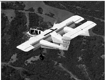 |
In 1971, NASA Ames Program Manager James Weiberg had North American-Rockwell modify the third prototype, YOV-10A Bronco, a small STOL twin-engine light armed reconnaissance aircraft (LARA), with an Alvarez-Calderon rotating cylinder flap system. As well as installing the cylinder, which was 12 inches in diameter, technicians cross-shafted the plane’s two Lycoming T53-L-11 turboshaft engines for increased safety, using the drive train from a Canadair CL-84 Dynavert, a twin-engine tilt rotor testbed. The YOV-10As standard three-bladed propellers were replaced with the four-bladed propellers used on the CL-84, though reduced in diameter so as to furnish adequate clearance of the propeller disk from the fuselage and cockpit. The rotating cylinder, between the wing and flap, energized the plane’s boundary layer by accelerating airflow over the flap. The flaps were modified to entrap the plane’s propeller slipstream, and the combination thus enabled steep approaches and short landings.[1355]
Before attempting flight trials, Ames researchers tested the modified YOV-10A in the Center’s 40- by 80-foot wind tunnel, measuring
changes in boundary layer flow at various rotation speeds. They found that at 7,500 revolutions per minute (rpm), equivalent to a rotational speed of 267.76 mph, the flow remained attached over the flaps even when they were set vertically at 90 degrees to the wing. But in the course of 34 flight-test sorties by North American-Rockwell test pilot Edward Gillespie and NASA pilot Robert Innis, researchers found significant differences between tunnel predictions and real-world behavior. Flight tests revealed that the YOV-10A had a lift coefficient fully a third greater than the basic YOV-10. It could land with approach speeds of 55 to 65 knots, at descent angles up to 8 degrees, and at flap angles up to 75 degrees. Researchers found that
 Rotation angles to flare were quite large and the results were inconsistent. Sometimes most of the sink rate was arrested and sometimes little or none of it was. There never was any tendency to float. The pilot had the impression that flare capability might be quite sensitive to airspeed (CL)[1356] at flare initiation. None of the landings were uncomfortable.[1357]
The modified YOV-10A had higher than predicted lift and down – wash values, likely because of wind tunnel wall interference effects. It also had poor lateral-directional dynamic stability, with occasional longitudinal coupling during rolling maneuvers, though this was a characteristic of the basic aircraft before installation of the rotating cylinder flap and had, in fact, forced addition of vertical fin root extensions on production OV-10A aircraft. Most significantly, at increasing flap angles, "deterioration of stability and control characteristics precluded attempts at landing,”[1358] manifested by an unstable pitch-up, "which required full nose-down control at low speeds” and was "a strong function of flap deflection, cylinder operation, engine power and airspeed.”[1359]
As David Few subsequently noted, the YOV-10A’s rotating cylinder flap-test program constituted the first time that: "a flow-entrainment and boundary-layer-energizing device was used for turning the flow downward and increasing the wing lift. Unlike all or most pneumatic boundary layer control, jet flap, and similar concepts, the mechanically driven rotating cylinder required very low amounts of power; thus there was little degradation to the available takeoff horsepower.”[1360]
Unfortunately, the YOV-10A did not prove to be a suitable research aircraft. As modified, it could not carry a test observer, had too low a wing loading—just 45 pounds per square foot—and so was "easily disturbed in turbulence.” Its marginal stability characteristics further hindered its research utility, so after this program, it was retired.[1361]
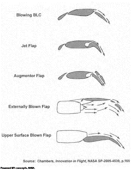
 NASA’s next foray in BLC research was a cooperative program between the United States and Canada that began in 1970 and resulted in NASA’s Augmentor Wing Jet STOL Research Aircraft (AWJSRA) program. The augmentor wing concept was international in origin, with significant predecessor work in Germany, France, Britain, Canada, and the United States.[1362] The augmentor wing included a blown flap on the trailing edge of a wing, fed by bleed air taken from the aircraft’s engines, accelerating ambient air drawn over the flap and directing it downward to produce lift, using the well-known Coanda effect. Ames researchers conducted early tunnel tests of the concept using a testbed that used a J85 engine powering two compressors that furnished air to the wind tunnel model.[1363] Encouraged, Ames Research Center and Canada’s Department of Industry, Trade, and Commerce (DTIC) moved to collaborate in flying
 |
 |
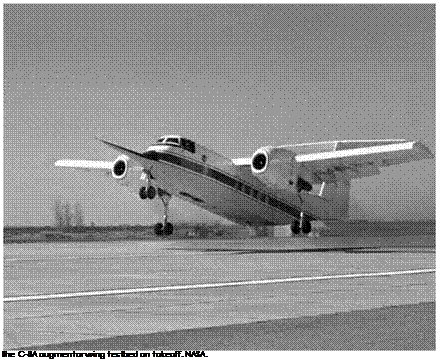
a testbed system. Initially, researchers examined putting an augmentor wing on a modified U. S. Army de Havilland CV-7A Caribou twin-piston- engine light STOL transport. But after studying it, they chose instead its bigger turboprop successor, the de Havilland C-8A Buffalo.[1364] Boeing, de Havilland, and Rolls-Royce replaced its turboprop engines with Rolls – Royce Spey Mk 801-SF turbofan engines modified to have the rotating lift nozzle exhausts of the Pegasus engine used in the vectored-thrust P.1127 and Harrier aircraft. They also replaced its high aspect ratio wing with a lower aspect ratio wing with spoilers, blown ailerons, augmentor flaps, and a fixed leading-edge slat. Because it was intended strictly as a low-speed testbed, the C-8A was fitted with a fixed landing gear. As well, it had a long proboscis-like noseboom, which, given the fixed gear and classic T-tail high wing configuration of the basic Buffalo from which it was derived, endowed it with a quirky and somewhat thrown-together appearance. The C-8A project was headed by David Few, with techni-
cal direction by Hervey Quigley, who succeeded Few as manager in 1973. The NASA pilots were Robert Innis and Gordon Hardy. The Canadian pilots were Seth Grossmith, from the Canadian Ministry of Transport, and William Hindson, from the National Research Council of Canada.[1365]
 The C-8A augmentor wing research vehicle first flew on May 1, 1972, and subsequently enjoyed great technical success.[1366] It demonstrated thrust augmentation ratios of 1.20, achieved a maximum lift coefficient of 5.5, flew approach speeds as low as 50 knots, and took off and landed over 50-foot obstructions in as little as 1,000 feet, with ground rolls of only 350 feet. It benefitted greatly from the cushioning phenomena of ground effect, making its touchdowns "gentle and accurate.”[1367] Beyond its basic flying qualities, the aircraft also enabled Ames researchers to continue their studies on STOL approach behavior, flightpath tracking, and the landing flare maneuver. The Ames Avionics Research Branch used it to help define automated landing procedures and evaluated an experimental NASA-Sperry automatic flightpath control system that permitted pilots to execute curved steep approaches and landings, both piloted and automatic. Thus equipped, the C-8A completed its first automatic landing in 1975 at Ames’s Crows Landing test facility. Ames operated it for 4 years, after which it returned to Canada, where it continued its own flight-test program.[1368]
Upper surface blowing (USB) constituted another closely related concept for using accelerated flows as a means of enhancing lift production. Following on the experience with the augmentor wing C-8A testbed, it became NASA’s "next big thing” in transport-related STOL
aircraft research. Agency interest in USB was an outgrowth of NACA – NASA research at Langley and Ames on BLC and the engine-bleed-air – fed jet flap, exemplified by tests in 1963 at Langley with a Boeing 707 jet airliner modified to have engine compressor air blown over the wing’s trailing-edge flaps. An Ames 40-foot by 80-foot tunnel research program in 1969 used a British Hunting H.126, a jet-flap research aircraft flight – tested between 1963 and 1967. It used a complex system of ducts and
nozzles to divert over half of its exhaust over its flaps.[1369] As a fully external system, the upper surface concept was simpler and less structurally intrusive and complex than internally blown systems such as the aug – mentor wing and jet flap. Consequently, it enjoyed more success than these and other concepts that NASA had pursued.[1370]
 In the mid-1950s, Langley’s study of externally blown flaps used in conjunction with podded jet engines, spearheaded by John P. Campbell, had led to subsequent Center research on upper surface blowing, using engines built into the leading edge of an airplane’s wing and exhausting over the upper surface. Early USB results were promising. As Campbell recalled, "The aerodynamic performance was comparable with that of the externally blown flap, and preliminary noise studies showed it to be a potentially quieter concept because of the shielding effect of the wing.” [1371] Noise issues meant little in the 1950s, so further work was dropped. But in the early 1970s, the growing environment noise issue and increased interest in STOL performance led to USB’s resurrection. In particular, the evident value of Langley’s work on externally blown flaps and upper surface blowing intrigued Oran Nicks, appointed as Langley Deputy Director in September 1970. Nicks concluded that upper surface blowing "would be an optimum approach for the design of STOL aircraft.”[1372] Nicks’s strong advocacy, coupled with the insight and drive of Langley researchers including John Campbell, Joseph Johnson, and
Arthur Phelps, William Letko, and Robert Henderson, swiftly resulted in modification of an existing externally blown flap (EBF) wind tunnel model to a USB one. The resulting tunnel tests, completed in 1971, confirmed that the USB concept could result in a generous augmentation of lift and low noise. Encouraged, Langley researchers expanded their USB studies using the Center’s special V/STOL tunnel, conducted tests of a much larger USB model in Langley’s Full-Scale Tunnel, and moved on to tests of even larger models derived from modified Cessna 210 and Aero Commander general-aviation aircraft to acquire data more closely matching full-size aircraft. At each stage, wind tunnel testing confirmed that the USB concept offered high lifting properties, warranting further exploration.[1373]
 Langley’s research on EBF and USB technology resulted in application to actual aircraft, beginning with the Air Force’s experimental Advanced Medium STOL Transport (AMST) development effort of the 1970s, a rapid prototyping initiative triggered by the Defense Science Board and Deputy Secretary of Defense David Packard. Out of this came the USB Boeing YC-14 and the EBF McDonnell-Douglas YC-15, evaluated in the 1970s in similar fashion to the Air Force’s Lightweight Fighter (LWF) competition between the General Dynamics YF-16 and Northrop YF-17. Unlike the other evaluation, the AMST program did not spawn a production model of either the YC-14 or YC-15. NASA research benefited the AMST effort, particularly Boeing’s USB YC-14, which first flew in August 1976. It demonstrated extraordinary performance during flight-testing and a 1977 European tour. The merits of YC-14-style USB impressed the engineers of the Soviet Union’s Antonov design bureau. They subsequently produced a transport, the An-72/74, which bore a remarkable similarity to the YC-14.[1374]
 |
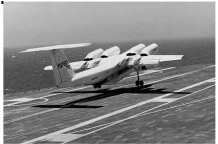 |
In January 1974, NASA launched a study program for a Quiet Short – Haul Research Airplane (QSRA) using USB. The QSRA evolved from earlier proposals by Langley researchers for a quiet STOL transport, the QUESTOL, possibly using a modified Douglas B-66 bomber, an example of which had already served as the basis for an experimental laminar flow testbed, the X-21. However, for the proposed four-engine USB, NASA decided instead to modify another de Havilland C-8, issuing a contract to Boeing as prime contractor for the conversion in 1976.[1375] The QSRA thus benefited fortuitously from Boeing’s work on the YC-14. Again, as with the earlier C-8 augmentor wing, the QSRA had a fixed landing gear and a long conical proboscis. Four 7,860-pound-thrust Avco Lycoming YF102 turbofans furnished the USB. As the slotted flaps lowered, the exhaust followed their curve via Coanda effect, creating additional propulsive lift. First flown in July 1978, the QSRA could take off and land in less than 500 feet, and its high thrust enabled a rapid climbout while making a steep turn over the point from which it became airborne. On approach, its high drag allowed the QSRA to execute a steep approach, which enhanced both its STOL performance and further reduced its
already low noise signature.[1376] It demonstrated high lift coefficients, from 5.5 to as much as 11. Despite a moderately high wing-loading of 80 pounds per square foot, it could fly at landing approach speeds as low as 60 knots. Researchers evaluated integrated flightpath and airspeed controls and displays to assess how precisely the QSRA could fly a precision instrument approach, refined QSRA landing performance to the point where it achieved carrier-like precision landing accuracy, and, in conjunction with Air Force researchers, used the QSRA to help support the development of the C-17 transport, with Air Force and McDonnell – Douglas test pilots flying the QSRA in preparation for their flights in the much larger C-17 transport. Lessons from display development for the QSRA were also incorporated in the Air Force’s MC-130E Combat Talon I special operations aircraft, and the QSRA influenced Japan’s development of its USB testbed, the ASKA, a modified Kawasaki C-1 with four turbofan engines flown between 1985 and 1989.[1377]
 Not surprisingly, as a result of its remarkable Short Take-Off and Landing capabilities, the QSRA attracted Navy interest in potentially using USB aircraft for carrier missions, such as antisubmarine patrol, airborne early warning, and logistical support. This led to trials of the QSRA aboard the carrier USS Kitty Hawk in 1980. In preparation, Ames researchers undertook a brief QSRA carrier landing flight simulation using the Center’s Flight Simulator for Advanced Aircraft (FSAA), and the Navy furnished a research team from the Carrier Suitability Branch at the Naval Air Test Center, Patuxent River, MD. The QSRA did have one potential safety issue: it could slow without any detectable change in control force or position, taking a pilot unawares. Accordingly, before the carrier landing tests, NASA installed a speed indexer light system that the pilot could monitor while tracking the carrier’s mirror-landing
system Fresnel lens during the final approach to touchdown. The indexer used a standard Navy angle-of-attack indicator modified to show the pilot deviations in airspeed rather than changes in angle of attack. After final reviews, the QSRA team received authorization from both NASA and the Navy to take the plane to sea.
 Sea trials began July 10, 1980, with the Kitty Hawk approximately 100 nautical miles southwest of San Diego. Over 4 days, Navy and NASA QSRA test crews completed 25 low approaches, 37 touch-and-go landings, and 16 full-stop landings, all without using an arresting tail hook during landing or a catapult for takeoff assistance. With the carrier steaming into the wind, standard Navy approach patterns were flown, at an altitude of 600 feet above mean sea level (MSL). The initial pattern configuration was USB flaps at 0 degrees and double-slotted wing flaps at 59 degrees. On the downwind leg, abeam of the bow of the ship, the aircraft was configured to set the USB flaps at 30 degrees and turn on the BLC. The 189-degree turn to final approach to the carrier’s angled flight deck was initiated abeam the round-down of the flight deck, at the stern of the ship. The most demanding piloting task during the carrier evaluations was alignment with the deck. This difficulty was caused partially by the ship’s forward motion and consequent continual lateral displacement of the angle deck to the right with the relatively low QSRA approach speeds. In sum, to pilots used to coming aboard ship at 130 knots in high-performance fighters and attack aircraft, the 60-knot QSRA left them with a disconcerting feeling that the ship was moving, so to speak, out from under them. But this was a minor point compared with the demonstration that advanced aerospace technology had reached the point where a transport-size aircraft could land and takeoff at speeds so remarkably slow that it did not need either a tail hook to land or a catapult for takeoff. Landing distance was 650 feet with zero wind over the carrier deck and approximately 170 feet with a 30-knot wind over the deck. Further, the QSRA demonstrated a highly directional noise signature, in a small 35-degree cone ahead of the airplane, with noise levels of 90 engine-perceived noise decibels at a sideline distance of 500 feet, "the lowest ever obtained for any jet STOL design.”[1378]
The QSRA’s performance made it a crowd pleaser at any airshow where it was flown. Most people had never seen an airplane that large fly with such agility, and it was even more impressive from the cockpit. One of the QSRA’s noteworthy achievements was appearing at the Paris Air Show in 1983. The flight, from California across Canada and the North Atlantic to Europe, was completed in stages by an airplane having a maximum flying range of just 400 miles. Another was a demonstration landing at Monterey airport, where it landed so quietly that airport monitoring microphones failed to detect it.[1379]
 By the early 1980s, the QSRA had fulfilled the expectations its creators, having validated the merits of USB as a means of lift augmentation. Simultaneously, another Coanda-rooted concept was under study, the notion of circulation control around a wing (CCW) via blowing sheet of high-velocity air over a rounded trailing edge. First evaluated on a light general-aviation aircraft by researchers at West Virginia University in 1975 and then refined and tested by a David Taylor Naval Ship Research and Development (R&D) Center team under Robert Englar using a modified Grumman A-6A twin-engine attack aircraft in 1979, CCW appeared as a candidate for addition to the QSRA.[1380] This resulted in a full-scale static ground-test demonstration of USB and CCW on the QSRA aircraft and a proposal to undertake flight trials of the QSRA using both USB and CCW. This, however, did not occur, so QSRA at last retired in 1994. In its more than 15 years of flight research, it had accrued nearly 700 flight hours and over 4,000 STOL approaches and landings, justifying the expectations of those who had championed the QSRA’s development.[1381]





 sideslip