Category NASA’S CONTRIBUTIONS TO AERONAUTICS

Melting Your Troubles Away

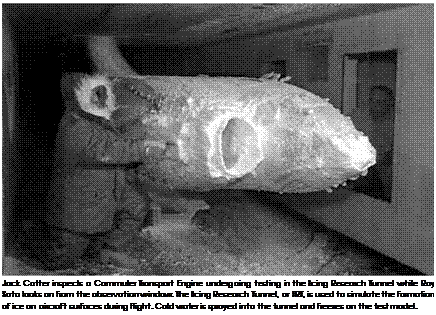
As quickly as the hazards of aircraft icing became known in the early days of aviation, inventive spirits applied themselves to coming up with ways to remove the hazard and allow the airplane to keep flying. These ideas at first took the form of understanding where and when icing occurs and then simply not flying through such conditions, then ways to prevent ice from forming in the first place—proactive anti-icing— were considered, and at the same time options for removing ice once it

Подпись: A King Air equipped with a de-icing boot on its wing leading edge shows how the boot removes some ice, but not on areas behind the boot. Подпись: 12

had formed—reactive de-icing—were suggested and tested in the field, in the air, and in the wind tunnel. Of all the options available, the three major ones are the pneumatic boot, spraying chemicals onto the air­craft, and channeling hot bleed air.[1224]

The oldest of the de-icing methods in use is the pneumatic boot sys­tem, invented in 1923 by the B. F. Goodrich Corporation in Akron, OH. The general idea behind the boot has not changed nearly a century later: a thick rubber membrane is attached to the leading edge of a wing air­foil. Small holes in the wing behind the boot allow compressed air to blow through, ever so slightly expanding the boot’s volume like a bal­loon. Any time that ice builds up on the wing, the system is activated, and when the boot expands, it essentially breaks the ice into pieces, which are quickly blown away by the relative wind of the moving air­craft. Again, although the general design of the boot system has not
changed, there have been improvements in materials science and sen­sor technology, as well as changes in the shape of wings used in vari­ous sizes and types of aircraft. In this manner, NASA researchers have been very active in coming up with new and inventive ways to enhance the original boot concept and operation.[1225]

Подпись: 12One way to ensure there is no ice on an aircraft is to remove it before the flight gets off the ground. The most common method for doing this is to spray some type of de-icing fluid onto the aircraft surface as close to takeoff as possible. The idea was first proposed by Joseph Halbert and used by the United Kingdom Royal Air Force in 1937 on the large flying boats then operated by Imperial Airways.[1226] Today, the chemicals used in these fluids usually use a propylene glycol or ethylene glycol base and may include other ingredients that might thicken the fluid, help inhibit corrosion on the aircraft, or add a color to the mixture for easier iden­tification. Often water is added to the mixture, which although counter­intuitive makes the liquid more effective. Of the two glycols, propylene is more environmentally friendly.[1227]

The industry standard for this fluid is set by the aeronautics division of the Society of Automotive Engineers, which has published standards for four types of de-icing fluids, each with slightly different properties and intentions for use. Type I has a low viscosity and is usually heated and sprayed on aircraft at high pressure to remove any snow, ice, or frost. Due to its viscosity, it runs off the aircraft very quickly and provides lit­tle to no protection as an anti-icing agent as the aircraft is exposed to snowy or icy conditions before takeoff. Its color is usually orange.[1228] Type II fluid has a thickening agent to prevent it from running very quickly off the aircraft, leaving a film behind that acts as an anti-icing agent until the aircraft reaches a speed of 100 knots, when the fluid breaks down from aerodynamic stress. The fluid is usually light yellow. Type III flu­id’s properties fall in between Type I and II, and it is intended for smaller,

Подпись: A Type 4 de-icing solution is sprayed on a commercial airliner before takeoff. Подпись: 12

slower aircraft. It is popular in the regional and business aviation mar­kets and is usually dyed light yellow. Type IV fluids are only applied after a Type I fluid is sprayed on to remove all snow, ice, and frost. The Type IV fluid is designed to leave a film on the aircraft that will remain for 30 to 80 minutes, serving as a strong anti-icing agent. It is usually green.[1229]

NASA researchers have worked with these fluids for many years and found uses in other programs, including the International Space Station. And during the late 1990s, a team of engineers from the Ames Research Center (ARC) at Moffett Field, CA, came up with an anti-icing fluid that was nontoxic—so much so that it was deemed "food grade” because its ingredients were approved by the U. S. Government for use in food— namely ice cream—and promised to last longer as an anti-icing agent for aircraft, as well as work as an effective de-icing agent. Although it
has not found wide use in the aviation industry, NASA did issue a license to a commercial firm who now sells the product to consumers as "Ice Free,” a spray for automobile windshields that can provide protection from snow or ice forming on a windshield in temperatures down to 20 degrees Fahrenheit (-7 degrees Celsius).[1230]

Подпись: 12The third common technique for dealing with ice accretion is the hot bleed air method. In this scheme, hot air is channeled away from the air­craft engines and fed into tubes that run throughout the aircraft near the areas where ice is most likely to form and do the most damage. The hot air warms the aircraft skin, melting away any ice that is there and discour­aging any ice from forming. The hot gas can also be used as the source of pressurized air that inflates a rubber boot, if one is present. While the idea of using hot bleed air became most practical with the introduction of jet engines, the basic concept itself dates back to the 1930s, when NACA engineers proposed the idea and tested it in an open-air-cockpit, bi-wing airplane. The in-flight experiments showed that "a vapor-heating system which extracts heat from the exhaust and distributes it to the wings is an entirely practical and efficient method for preventing ice formation.”[1231]

As for melting ice that can accrete on or in other parts of an air­craft, such as windshields, protruding Pitot tubes, antennas, and car­buretors on piston engines, electrically powered heaters of one kind or another are employed. The problem of carburetor ice is especially important and the one form of icing most prevalent and dangerous for thousands of General Aviation pilots. NASA has studied carburetor ice for engines and aircraft of various configurations through the years[1232] and in 1975 surveyed the accident database and found that between 65 and 90 accidents each year involve carburetor icing as the probable cause. And when there are known carburetor icing conditions, between 50 and 70 percent of engine failure accidents are due to carburetor icing. Researchers found the problem to be particularly acute for pilots
with less than 1,000 hours of total flying time and overall exposed about 144 persons to death or injury each year.[1233]

Accelerated Progress

NASA’s role in high-angle-of-attack technology rapidly accelerated begin­ning in 1971. Extensive research was conducted with generic models, simulator techniques for assessing high-alpha behavior were developed, and test techniques were upgraded. Active participation in the F-14, F-15, and B-1 development programs was quickly followed by similar research for the YF-16 and YF-17 Lightweight Fighter prototypes, as
well as later efforts for the F-16, F-16XL, F/A-18, X-29, EA-6B, and X-31 programs. Summaries of Langley’s contributions in those programs have been documented, and equally valuable contributions from Dryden and Ames will be described herein.[1290] Brief highlights of a few NASA contri­butions and their technical impacts follow.

NACA-NASA and Ducted-Fan V/STOL Research Programs

Подпись: 14One of the more intriguing forms of aircraft propulsion is the ducted fan: the fan enclosed within a ring and powered by a drive train from an engine typically located elsewhere in the aircraft. Researchers inter­ested in V/STOL flight expended great effort on ducted-fan approaches, and indeed, such an approach is incorporated on the Joint Strike Fighter, the Lockheed Martin F-35 Lightning II. Though ducted-fan propulsion for Conventional Take-Off and Landing aircraft had enjoyed at best a mixed record, those advocating it for V/STOL applications were hope­ful it would prove more successful. Ducted-fan options included piv­oting fans that could furnish direct lift, like tilt rotors, then pivot to furnish power for wing-borne forward flight, or rely on horizontal fans in a wing or fuselage to generate vertical lift, or combinations of these.

Ducted-fan aircraft intended for conventional flight were tried in many nations. Likewise, ducted-fan V/STOL adherents in various coun­tries had proposed concepts for such craft. But the first two American ducted-fan V/STOL airplanes—that is, ducted-fan aircraft with wings, as opposed to various Hiller and Piasecki flying platforms—were the Doak Model 16, designated the VZ-4, and the Vanguard Omniplane. Each rep­resented a different approach, though, of the two, only the Doak flew.[1401]

Подпись: 14 NACA-NASA and Ducted-Fan V/STOL Research Programs

The Doak began as an Army research project, first flying in February 1956. A pleasing and imaginative design of conventional straight wing aerodynamic layout, it had a single 860-horsepower Lycoming YT53 turboshaft engine driving two pivoted ducted fans on the wingtips. During hover, variable inlet guide vanes in the ducts furnished roll con­trol, with pitch and yaw control provided by vectored jet exhaust from

a variable tail nozzle. The Doak proved that its design approach worked, readily making vertical descents, transitions to conventional flight, and transition back to hover and landing, accelerating in just 17 seconds from 0 to 200 knots. It arrived at the NACA’s Langley laboratory in September 1957. Testing revealing a mix of undesirable handling qualities across its flight envelope, with one subsequent NASA study concluding that it

Подпись: 14suffered from low inherent control power about all axes, sensitivity to ground-effect disturbances, large side forces associated with the large ducts, and a large (positive) dihe­dral effect which restricted operation to calm-air conditions and no crosswinds. No large STOL performance benefit was evident with this design.[1402]

During vertical descents, it buffeted with alternate left-and-right wing­dropping. This became so severe as the plane approached stall angle that "roll control was not adequate to keep the aircraft upright,” noted pilot Jack Reeder. Large nose-up pitching moments required careful speed and duct-angle management to prevent duct-lip airflow stalling. In hover, the inlet guide vanes were "very inadequate.” In ground effect, Reeder noted:

if lifted clear of the ground by several feet, uncontrollable yawing and persistent lateral upsetting tendencies have been encountered. With the weak yaw control and, particularly the weak roll control, the unindoctrinated pilot may find himself unable to control the aircraft.[1403]

The Doak Company closed in 1960, and NASA retired the airplane in 1972. By that time, a ducted-fan successor, the Bell Aerospace Textron X-22A, was already flying. Far more unconventional in appearance than was the Doak, it nevertheless owed a technical debt to the earlier design. As NASA researchers had concluded from the VZ-4’s testing, the little Doak had "indicated the feasibility as well as the inherent problems of the tilt-duct concept, which helped the X-22 design which followed.”[1404]

Bell Aerospace Textron’s X-22A grew out of company studies in the mid-1950s. Successive examination of Bell-proposed military concepts led to increasing service interest by the Navy, Air Force, Marine Corps, and Army for a range of transport, rescue, and counterinsurgency appli­cations. In late 1962, the U. S. Navy signed a development contract with Bell for a half-scale flying testbed of one of the company’s proposed designs. This became the X-22A, two of which were built. Because the loss of any one fan would spell disaster, the X-22A used four General Electric T58 turboshaft engines, interconnected to the ducted fans so that an engine failure would not result in a loss fan power. NASA sup­ported Bell’s development with extensive wind tunnel studies at Ames and Langley. Control was exercised by changing the pitch of each of the four propellers and by moving the four elevons. These eight variables were used to control the X-22 in normal flight with ducts horizontal and in hover with ducts vertical. In horizontal flight, pitch and roll were con­trolled by the elevons and yaw by differential variation of propeller pitch. For hovering flight, propeller pitch adjustments controlled pitch and roll, while elevon movements controlled yaw. During transition, control func­tions were phased in gradually as a function of duct tilt angle. The pilot was provided with artificial "feel” in yaw during forward flight, but this was removed during transition to hover. Pitch and roll "feel” were provided by a hydroelectric system that applied stick reactions proportional to g-forces. For hover, transition, and low-speed flight, a Stability Augmentation System was used to improve aircraft stability and handling characteristics. The X-22A was equipped with a sophisticated Variable Stability and Control System (VSCS) developed by the Calspan Corp. This allowed it to be pro­grammed to behave like other existing or projected VTOL aircraft for assessment of flight characteristics. The VSCS interacted with the Smiths Industries head-up display (HUD) and the Kaiser Electronics head-down display (HDD). Data inputs to the VSCS included those from a low-speed airspeed sensor, the Linear Omnidirectional Resolving Airspeed System (LORAS), invented by Calspan’s Jack Beilman.[1405]

Подпись: 14The first X-22A flew March 17, 1966, but a hydraulic system fail­ure led to the loss of the aircraft in August of that year during an emer­gency vertical landing, fortunately without injury to the crew. The second X-22A became one of the more successful research aircraft ever flown,

Подпись: The X-22A at altitude. NASA. Подпись: 14

completing over 500 flights and over 1,300 transitions, between com­mencement of its flight-test program at the end of January 1967 through its retirement from flight-testing 17 years later. It hovered at over 8,000 feet altitude and achieved a forward speed of 315 mph, proving conclu­sively that a tilt duct vehicle could fly faster than could a conventional helicopter. In May 1969, it was turned over to the Navy, which appointed Calspan to continue the flight-test program and fly it as a variable stabil­ity research and training aircraft. Eventually, three NASA test pilots flew it, two of whom were formerly at Calspan Corporation—Rogers Smith and G. Warren Hall—and Ron Gerdes from Ames. Assessing the X-22A’s place in V/STOL history, NASA researchers concluded:

Hover operation Out of Ground Effect (OGE) in no wind was rated excellent, with no perceptible hot-gas ingestion. A 12% positive thrust increase was generated In Ground Effect (IGE) by the favorable fountain. Airframe shaking and buffeting occurred at wheel heights up to about 15 ft, and cross-wind effects were quite noticeable because of large side forces gen­erated by the ducts. Vertical cross-wind landings required an excessive bank angle to avoid lateral drift. STOL performance was rated good by virtue of the increased duct-lifting forces. Highspeed performance was limited by inherent high drag associated with the four large ducts. Transition to conven­tional flight could be made easily because of a wide transition
corridor; however, inherent damping was low. Deceleration and descent at low engine powers caused undesirable duct "buzz” as a result of flow separation on the lower duct lips. Vortex gen­erators appreciably improved this flow-separation problem.[1406]

The X-22A proved to be a successful and versatile research tool, flying for at least 17 years and providing much valuable information on ducted VTOL systems and the larger operational issues of VTOL and STOL aircraft.

Подпись: 14NASA expended a great deal of study effort examining the benefits of lift-fan technology and various design approaches that might be taken in design of a practical military and civil lift-fan aircraft. In the course of these trials, involving model tests, tests of candidate fan technolo­gies, and examinations of lift-fan aircraft (such as the ill-fated Vanguard Omniplane), researchers studied an experimental Army-Ryan program, the XV-5A Vertifan. The XV-5A was an ill-fated program, like its con­temporary, the Army-Lockheed XV-4 Hummingbird, which is discussed subsequently. Between them, the aircraft built of these two types killed three test pilots and nearly a fourth. Powered by two General Electric J85 engines driving in-wing fans and a nose pitch-control fan (like the Vanguard Omniplane) and used for conventional propulsion, the first of two XV-5As flew in 1964 but crashed during a public demonstration at Edwards AFB in August 1965, killing Ryan test pilot Lou Everett. The sec­ond fared little better, crashing in October 1966 at Edwards after one lift fan ingested a rescue hoist deployed from the aircraft, causing an asym­metric loss of lift. Air Force test pilot Maj. David Tittle perished while ejecting from the ailing aircraft, which, in sad irony, impacted with sur­prisingly little damage. Rebuilt as the XV-5B with some changes to its avi­onics, cockpit layout, ejection seat, and landing gear, it flew again in 1968, flying afterward at Ames Research Center on a variety of NASA investi­gations led by David Hickey, until its retirement in 1974.[1407]

Подпись: The XV-5B in a hover test at Ames Research Center. NASA. Подпись: 14

Among these studies were tests in and out of ground effect of var­ious wing and inlet configurations, exit-vane designs, nose fans, and control devices. The research studies focused on problems of transi­tion from vertical to horizontal flight, and on improvements of the lift fans to provide quieter, smaller fans with greater thrust. These studies were funded in part by the U. S. Army Aeronautical Research Laboratory, reflecting the Army’s interest in V/STOL aircraft technology and matu­ration. Ames researchers found that the XV-5B could take off and land vertically from an area the size of a tennis court; hover in midair for several minutes like a helicopter; and fly straight up, down, backward, or to either side at speeds up to 25 mph. As well, it could operate like a conventional jet airplane using a runway, flying up to 525 mph. However, though a NASA summary report on V/STOL concepts concluded, "The lift-fan concept proved to be relatively free of mechanical problems,” tests revealed that the XV-4B was still far from a practical vehicle. Hot – gas ingestion degraded engine performance while in ground effect, drag

from the fan installations limited STOL performance, combinations of fan overspeed and a nose-up tendency complicated conversions, and the design layout hinted at a potential deep-stall problem characteristic of many T-tail aircraft. NASA concluded: "This configuration has limited high-speed potential because of the relatively thick wing section needed to house the lift fans and vectoring hardware.”[1408]

Подпись: 14As part of an Advanced Short Take-Off and Vertical Landing (ASTOVL) study program that began in 1980, NASA continued detailed studies of ducted lift fans, among other propulsion concepts intended for a supersonic successor to the vectored-thrust AV-8B Harrier II. The outcome of that development effort was validated in the successful flight­testing of a lift fan on the STOVL variant of the Lockheed Martin X-35, the experimental proof-of-concept demonstrator for the F-35 Joint Strike Fighter a quarter century later.[1409] In this regard, lessons learned from NASA’s various lift-fan programs, particularly the XV-5A and XV-5B, com­piled by Ames test pilot and distinguished V/STOL researcher Ronald

M. Gerdes, are included as an appendix to this study.

Proving the Tilt Rotor: From XV-3 and X-100 to XV-15 and on to V-22

One V/STOL concept that proved to have enduring appeal was the tilt rotor, which entered production and operational service with the joint – service Bell-Boeing V-22 Osprey. The tilt rotor functioned like a twin-rotor helicopter during lift-off, hover, and landing. But for cruising flight, it tilted forward to operate as high aspect ratio propellers. Such a concept meant that the tilt rotor would necessarily have its rotors pod-mounted on the tips of conventional wings.[1410]

Though various designers across the globe envisioned tilt rotor con – vertiplanes, the first successful one was the Bell Model 200, produced by Bell Helicopter for the Air Force and Army as the XV-3 under a joint Army-USAF "convertiplane” program started in August 1950. Relatively

Подпись: The Bell XV-3 tilt rotor shown after transitioning to conventional flight during NASA testing in April 1961. NASA. Подпись: 14

streamlined and looking more like an airplane than did many early V/STOL testbeds, the XV-3 had an empty weight of 3,600 pounds and a normal gross weight of just 4,800 pounds, as it was relatively under­powered. A single Pratt & Whitney R985 radial piston engine producing 450 horsepower drove two three-bladed rotors via drive shafts. With this propulsion system, the XV-3 completed its first hover in August 1955, piloted by Floyd Carlson.[1411]

Flight-testing over the next year demonstrated flight at progressive levels of rotor tilt, though it had not made a full 90-degree conversion of its rotors to level position before it crashed while landing in October 1956 from a rotor instability. Bell test pilot Dick Stansbury survived but was seriously injured. Afterward, the second XV-3 was equipped with stiffer two-bladed rotors. On December 18, 1958, Bell test pilot Bill Quinlan achieved a full conversion from a helicopter-like ascent to for­ward flight like an airplane. During the XV-3 flight-test program, the lack of engine power prevented it from hovering out of ground effect. When
it did hover in ground effect, reflected rotor wash caused unpredictable darting, something the tilt rotor V-22 experienced four decades later during its testing. The lack of an SAS further exacerbated pilot hover challenges, and in gusty air, high pilot workload was required to hover. The XV3 transited rapidly from hover to conventional flight, requiring only small pitch changes across the range of speed and angle of attack encompassed by the transition corridor. Pitch and yaw dynamic insta­bility triggered by side forces as blade angle was increased limited maxi­mum cruise speed to 140 knots and pointed to rotor dynamics and flight control challenges that future tilt rotors would have to overcome. In all of this research, Bell blended extensive analytical studies and scale model experiments with tests in the Ames 40-foot by 80-foot wind tunnel.[1412]

Подпись: 14In May 1959, the surviving XV-3 was delivered to the Air Force Flight Test Center at Edwards Air Force Base (AFB), where it under­went a 3-month Air Force evaluation before being delivered for more extensive testing and research to the Ames Research Center. During Edwards’s testing, Maj. Robert Ferry successfully demonstrated a power – off reconversion to a vertical autorotation descent and landing, an impor­tant milestone. At Ames, Hervey Quigley carried out the research, and Don Heinle and Fred Drinkwater conducted most of the test flying, in the course of which the XV-3 was modified with a large ventral fin to improve its directional stability. In the Ames tests, flapping of the teeter­ing rotors during maneuvers introduced moments that reduced damp­ing of the longitudinal and lateral-directional oscillations to near zero at speeds approaching 140 knots. Despite these problems and despite being underpowered and limited in payload, the XV-3 proved the capa­bility of the tilt rotor to perform in-flight conversions between the heli­copter and the airplane modes, though much work on understanding rotor dynamics and flight control issues needed to be done. The XV-3 flew at Ames until summer 1962, when it began an extensive series of wind tunnel studies in the 40-foot by 80-foot tunnel. In November 1968, during 200-mph tunnel trials, fatigue failure in one wingtip led to sep­aration of the rotors and their pylons from the aircraft, bringing its 13-year test career, at last, to an end. By that time, it had validated the tilt rotor concept, thus influencing—as discussed subsequently—the next step forward in experimental tilt rotor design, the XV-15. That vehicle,

of course, would exert an even greater influence upon development of its operational successor, the V-22 Osprey.[1413]

Before settlement on the tilt rotor as exemplified by Bell’s design approach with the XV-3, researchers considered another seemingly closely related concept: the tilt prop. However, the tilt prop idea was different. Researchers had long known that rotating propellers gener­ate a powerful side force, and Curtiss-Wright Corporation engineers envisioned taking advantage of this property by using smaller diame­ter and lower aspect ratio propellers than tilt rotors that could use this "radial lift force” as a means of lifting a V/STOL airplane vertically. Such a design, they hoped, would have higher top-end speed after conversion than an XV-3-like tilt rotor approach.[1414]

Подпись: 14The result was the X-100, a small testbed whose twin broad-chord propellers were driven by a single Lycoming YT53-L-1 turboshaft engine. Its jet exhaust vented through an omnidirectional tail nozzle, furnishing low-speed pitch and yaw control. Differential propeller operation fur­nished roll control during hover. The X-100 underwent testing in Ames 40-foot by 80-foot tunnel and extensive ground trials before making its first flight in March 1960. In August, it underwent a NASA flight evalu­ation, after which it went to Langley Research Center for further test­ing, including downwash effects on various kinds of ground surfaces.[1415] Langley pilot Jack Reeder found it longitudinally unstable during con­versions, something "very undesirable during landing approaches, par­ticularly under instrument conditions.” During hover it demonstrated "erratic wing dropping and yawing,” necessitating "noticeably large” cor­rective control inputs to correct, and "weak” yaw control that prevented holding a desired heading. It "settled rapidly toward the ground when upset in bank or pitch attitude” while in ground effect, again, something he found "very undesirable.” On the positive side, he found that "The X-100 aircraft suffers no apparent stall problems.”[1416]

Подпись: 14 NACA-NASA and Ducted-Fan V/STOL Research Programs

In October 1961, the X-100 was seriously damaged in a hovering accident that, fortunately, did not result in injury to its pilot. Despite its mediocre performance, it had demonstrated the feasibility of the radial – lift propeller concept. Thus, Curtiss-Wright continued pursuing the tilt prop approach but now chose to make a four-propeller craft with equal span fore and aft wings, rather than an X-100-like twin-rotor design. The company subsequently received an Air Force developmental contract for this larger and more powerful design, which became the experimen­tal X-19. Of the two that were built, only the first flew, and it had a brief and troubled flight-test program before crashing in August 1965 at the FAA’s National Aviation Facilities Experimental Center (NAFEC) after experiencing a catastrophic gearbox failure. Fortunately, its crew ejected from the now-propless testbed before it plunged to Earth. At the compa­ny’s request, the X-19 program was terminated the following December. The accident, one NASA authority concluded, "exemplified an inherent deficiency of this VTOL (lift) arrangement: to safely transmit power to the extremities of the planform, very strong (and fatigue-resistant)

structures must be incorporated with an obvious weight penalty.”[1417] The future belonged to the tilt rotor, not tilt prop.

Подпись: 14Though tests with the XV-3 had identified numerous challenges in stability and control, handling qualities, and the dynamics of the combined wing-pylon-rotor interactions, the program encouraged tilt rotor proponents to continue their studies. So promising did the tilt rotor appear that the Army and NASA formed a joint project office at Ames to study tilt rotor technology and undertook a number of sim­ulations of such systems to refine project goals and efficiencies.[1418] In 1971, Dr. Leonard Roberts of Ames’s Aeronautics and Flight Mechanics Directorate established a V/STOL Projects Office under Woody Cook to develop and flight-test new V/STOL aircraft. That same year, in partner­ship with the Army, NASA launched a competitive development program for the design and fabrication of two tilt rotor research aircraft. Four companies responded, and Boeing and Bell received study contracts in October 1972. After evaluating each proposal, NASA selected Bell’s Model D301 for development, issuing Bell a contract at the end of July 1973.[1419]

As developed, the XV-15 was an elegant and streamlined technol­ogy demonstrator, a two-pilot testbed powered by twin Lycoming T53 turboshafts rated at 1,550 horsepower each, driving 25-foot-diameter three-bladed prop rotors. Bell completed the first XV-15 in October 1976 and, after ground tie-down testing, undertook its first preliminary hover

Подпись: 14 NACA-NASA and Ducted-Fan V/STOL Research Programs

trials in May 1977, piloted by Ron Erhart and Dorman Cannon. In May 1978, before flight envelope expansion, it went into the Ames 40-foot by 80-foot wind tunnel for extensive stability, performance, and loads tests. Ames’s aeronautical facilities greatly influenced the XV-15’s development, particularly simulations of anticipated behavior and operational nuances, and tilt rotor performance and dynamic tests in the wind tunnel.[1420]

The second XV-15 went to Dryden for contractor flight tests, con­ducted between April 1979 and July 1980, and was delivered to NASA for research in August.[1421] By that time, NASA, Army, and contractor researchers had already concluded:

The XV-15 tilt rotor has exhibited excellent handling quali­ties in all modes of flight. In the helicopter mode it is a sta­ble platform that allows precision hover and agility with low pilot workload. Vibration levels are low as are both internal and external noise levels. The conversion procedure is uncom­plicated by schedules, and it is easy to perform. During the
conversion or reconversion, acceleration or deceleration are impressive and make it difficult for conventional helicopters or airplanes to stay with the XV-15. Handling qualities are excellent within the airplane mode envelope investigated to date; however, gust response is unusual. Although internal noise levels are up somewhat in the airplane mode, external noise levels are very low. Overall the XV-15 is a versatile and unique aircraft which is demonstrating technology that has the potential for widespread civil and military application.[1422]

Подпись: 14Such belief in the aircraft led to its participation in the 1981 Paris Air Show, the first time NASA had demonstrated one of its research vehicles in an international venue. It was an important vote of confidence in tilt rotor technology, made more evident still by the XV-15’s stopover at the Royal Aircraft Establishment at Farnborough, where it demonstrated its capabilities before British aeronautical authorities. In 1995, 14 years after its first Paris appearance, the XV-15 would again fly at Le Bourget, this time in company with its successor, the Bell-Boeing V-22 Osprey.[1423]

Over its two-decade test program, the XV-15 was not immune to var­ious mishaps, though fortunately, no one was seriously injured. Both air­craft experienced various emergencies, including forced landings after engine failures, a close call from a bird strike that cracked a wing spar, a tree strike, near-structural failure caused by an unsuitable form of tita­nium alloy fortuitously discovered before it could do harm, intergran­ular corrosion that caused potentially dangerous hairline blade cracks, and even one major accident. In August 1991, the first XV-15 crashed while landing after an improperly secured nut separated from a linkage controlling one of the prop rotors. Pilots Ron Erhart and Guy Dabadie were not seriously injured, though the accident destroyed the aircraft.[1424]

In retrospect, the XV-15 was the most influential demonstrator air­craft program that Ames ever pursued. For a cost to taxpayers of $50.4 million, NASA and its partners significantly advanced the technology and capability of tilt rotor technology. In over two decades of flight operations, more than 300 guest pilots would fly in the XV-15. As well, it would operate from the New York Port Authority heliport, fly abroad,

Подпись: 14 NACA-NASA and Ducted-Fan V/STOL Research Programs

and go to sea, demonstrating its ability to operate from amphibious assault ships. Among the many at Ames who contributed to making the program a success were NASA’s Wally Deckert, Mark Kelly, and Demo Giulianetti, and the Army’s Paul Yaggy, Dean Borgman, and Kipling Edenborough, who furnished critical guidance and oversight as the project was being established. Dave Few, Army Lt. Col. James Brown, and John Magee served as Program Managers. Principal investigators were Laurel Schroers, Gary Churchill, Marty Maisel, and Jim Weiberg. The project pilots were Daniel Dugan, Ronald Gerdes, George Tucker, Lt. Col. Grady Wilson, and Lt. Col. Rick Simmons. They shepherded the XV-15 through two decades of research on flying qualities and stability and control evaluations, control law development, side stick controller tests, performance evaluations in all flight modes, acoustics tests, flow surveys, and documentation of its loads, structural dynamics, and aero – elastic stability characteristics, generating a useful database that was digitized by Ames and made available to industry and military custom­ers. In sum, the XV-15 did much to advance the V/STOL cause, partic­ularly that of the tilt rotor concept.[1425]

In particular, flight experience with the XV-15 contributed greatly to the development of the joint-service V-22 Osprey tilt rotor.[1426] This Bell – Boeing aircraft, now in service with the U. S. Marines, the U. S. Navy, and the U. S. Air Force, fulfills a variety of roles, including combat assault, insertion and support of special operations forces (SOF), combat search and rescue (CSAR), and logistical support. Time will tell whether the V-22 Osprey will come to enjoy the longevity and ubiquity attendant to conventional joint-service fixed and rotary wing transports, such as the legendary Douglas C-47, Lockheed C130, Bell UH-1, and Sikorsky H-53.

The Tu-144LL Handling Qualities Assessment

In Phase I, typical flights involved a climb and acceleration to supersonic speeds and cruise altitudes, 15 minutes of stable supersonic cruise, a descent and deceleration to subsonic cruise conditions for subsonic test points, and finally, approach and landing work.[1507] All 19 Phase I flights were accomplished by Tupolev crews. Flights 20 through 23 incorporated the NASA pilot evaluations at the beginning of Phase II. The descrip­tion of the Handling Qualities Assessment Experiment 2.4/2.4A will cen­ter on these flights, because they are of more special interest to NASA.[1508]

Подпись: 15Working with Tupolev chief test pilot Sergei Borisov and project engi­neer Vladimir Sysoev, USPET developed a set of efficient handling qual­ities maneuvers to be used on these flights. These maneuver sets were derived from the consensus reached among USPET members regard­ing the highest-priority tasks from Mach 2 to approach and landing. To assist the pilots, specifically defined maneuvers were repeated for dif­ferent flight conditions and aircraft configurations. These maneuver sets included

• Integrated test block (ITB): The ITB was a standard block of maneuvers consisting of pitch attitude captures, bank captures, heading captures, steady heading sideslips, and a level acceleration/deceleration.

• Parameter identification (PID) maneuvers: The PID maneuvers generated either a sinusoidal frequency sweep or a timed pulse train in the axis of interest and contributed to the dataset needed for the LOES analysis.

• Simulated engine failure: This consisted of retarding an outboard throttle to minimum setting, stabilizing on a trimmed condition, and performing a heading capture.

• Slow flight: Accomplished in both level and turning flight, this maneuver was flown at minimum airspeed.

Подпись: 15 Подпись: NASA and Russian engineers monitoring a U.S. evaluation flight from the Gromov Russian Federation State Scientific Center. NASA.

Structural excitation maneuvers: These maneuvers con­sisted of sharp raps on each control inceptor to excite and observe any aeroservoelastic response of the aircraft.

• Approaches and landings: Different configurations were specified to include canard retracted, lateral off­set, manual throttle, nose retracted (zero forward vis­ibility), simulated engine out, visual, and Instrument Landing System (ILS) approaches.52

Flight 20 was flown by an all-Russian crew but was observed from a control room at the Gromov Russian Federation State Scientific Center at the Zhukovsky Air Development Center.

This flight provided USPET with an excellent opportunity to observe Tu-144 planning and operations and prepared the team for the NASA piloted flights. With a better sense of Tupolev operations, USPET was able to develop English checklists and procedures to complement the Russian ones. Fullerton and Rivers learned all of the Russian-labeled
switches and controls and procedural calls. USPET made bound check­lists from the cardboard backs of engineering tablets, because office mate­rial was in short supply at that time in Russia. Flight 20 also allowed USPET engineers Jackson, Cox, and Princen and pilots Fullerton and Rivers to develop a working relationship with Tupolev project engineer Sysoev in developing the test cards for the U. S. flights. The stage was set for the first flight of a Tu-144 by a United States pilot.

Подпись: 15Flight 21 was scheduled for September 15, 1998. Fullerton and Rivers agreed that Fullerton would pilot this flight and Rivers would observe from the cockpit, taking notes, timing maneuvers, and assisting with the crew coordination. As it turned out, Fullerton’s communications failed during the flight, and Rivers had to relay Tupolev pilot Sergei Borisov’s comments to Fullerton. Borisov sat in the left seat and Fullerton in the right; Victor Pedos occupied the navigator’s seat and Anatoli Kriulin the flight engineer’s station. Rivers stood behind Borisov and next to Pedos. Jackson and Cox had seats in the Gromov control room. Flight 21 was to be a subsonic flight with handling qualities maneuvers completed by Fullerton during the climb, Mach 0.9 cruise, descent, low-altitude slow – flight maneuvering, and approach and landing tasks. Because of the shortage of tires, each flight was allowed only one landing. The multiple approaches flown were to low approach (less than 200-feet altitude) only.

The flight is best described by the flight test summary contained in a NASA report titled "A Qualitative Piloted Evaluation of the Tu-144”:

Shortly after take-off a series of ITBs were conducted for the take-off and the clean configurations at 2 km altitude. Acceleration to 700 km/hr was initiated followed by a climb to the subsonic cruise condition of Mach 0.9, altitude 9 km. Another ITB was performed followed by evaluations of a simu­lated engine failure and slow speed flight. After descent to 2 km, evaluations of slow speed flight in the take-off and landing con­figurations were conducted as well as an ITB and a simulated engine failure in the landing configuration. Following a descent to pattern altitude three approaches to 60 m altitude were con­ducted with the following configurations: a canard retracted configuration using the ILS localizer, a nominal configuration with a 100 m offset correction at 140 m altitude, and a nom­inal configuration using visual cues. The flight ended with a visual approach to touchdown in the nominal configuration.

However, due to unusually high winds the plane landed right at its crosswind limit, necessitating the Russian pilot in com­mand to take control during the landing. Total flight time was approximately 2 hours 40 minutes. The maximum speed and altitude was 0.9 Mach and 9 km.53

The flight completed all test objectives. Thorough debriefs ensued, the obligatory postflight party sponsored by Tupolev was held, and USPET began intensive training and planning for the first supersonic flight, to be flown just 3 days later.

Подпись: 15September 18 opened cool, clear, and much less gusty than the pre­ceding days. Flight 22 would be a Mach 2 mission to an altitude of 60,000 feet, with at least 20 minutes flight at twice the speed of sound. Rob Rivers was the NASA pilot for this flight. Pukhov’s only requirement for Rivers was that he no longer need his crutches by flight day. Two nights before, Bruce Jackson had helped Rivers practice using a cane for over an hour until Rivers was comfortable. At the next day’s preflight party, Rivers demonstrated to Pukhov his abilities without crutches, and his approval for the flight was assured. At 11:08 a. m. local time, the Tu-144 became airborne.

The flight is described below in Rivers’s original flight test report:

Flight Profile. The flight profile included takeoff and accelera­tion to 700 kilometers per hour (km/hr) to intercept the climb schedule to 16.5 kilometers (km) and Mach 2.0. The flight direction was southeast toward the city of Samara on the Volga River at a distance of 700 km from Zhukovsky. Approximately 20 minutes were spent at Mach 2.0 cruise which included an approximately 190 degree course reversal and a cruise climb up to a maximum altitude of 17.3 km. A descent and decel­eration to 9 km and Mach 0.9 was followed by a brief cruise period at that altitude and airspeed prior to descent to the traffic pattern at Zhukovsky Airfield for multiple approaches followed by a full stop landing on Runway 30.

Flight Summary. After all preflight checklists had been com­pleted, the evaluation pilot taxied Tu-144LL Serial Number

Подпись: 1577144 onto Runway 12, and the brake burn-in process was accomplished. At 11:08 brakes were released for takeoff, power was set at 98° PLA (partial afterburner), the start brake was released, and after a 30 sec takeoff roll, the aircraft lifted off at approximately 355 km/hr. The landing gear was raised with a positive rate of climb, the canard was retracted out of 120 m altitude, and the nose was raised out of 1000 m altitude. The speed was initially allowed to increase to 600 km/hr and then to 700 km/hr as the Vertical Regime Indicator (VRI) profile was intercepted. Power remained at 72° PLA (maximum dry power) for the climb until Mach 0.95 and CG of 47.5% at which point the throttles were advanced to maximum power, 115° PLA. The climb task was a high work­load task due to the sensitivity of the head up pitch refer­ence indicator, the sensitivity of the pitch axis, and the continual change in CG requiring almost continuous lon­gitudinal trim inputs. Also, since the instantaneous center of rotation is located at the pilot station, there are no cock­pit motion cues available to the pilot for pitch rate or atti­tude changes. Significant pitch rates can be observed on the pitch attitude reference indicator that are not sensed by the pilot. During the climb passing 4 km, the first of a repeating series of bank angle captures (±15°) and control raps in all three axes (to excite any aircraft structural modes) was com­pleted. These maneuvers were repeated at 6 km and when accelerating through Mach 0.7, 0.9, 1.1, 1.4, and 1.8. The bank angle captures demonstrated rather high roll forces and relatively large displacements required for small roll angles. A well damped (almost deadbeat) roll mode at all airspeeds up to Mach 2.0 was noted. The control raps showed in gen­eral a higher magnitude lower frequency response in all three axes at subsonic speeds and lower magnitude, higher frequency responses at supersonic speeds. The pitch response was in general of lower amplitude and frequency with fewer over­shoots (2-3) than the lateral and directional responses (4-5 overshoots) at all speeds. Also of interest was that the axis exhibiting the flexible response was the axis that was perturbed, i. e., pitch raps resulted in essentially only pitch responses. The motions definitely seemed to be aeroservoelastic in nature,

and with the strong damping in the lateral and directional axes, normal control inputs resulted in well damped responses. Level off at 16.5 km and Mach 1.95 occurred 19 minutes after takeoff. The aircraft was allowed to accelerate to Mach 2.0 IMN as the throttles were reduced to 98° PLA, and a series of control raps was accomplished. Following this, a portion of the Integrated Test Block set of maneuvers consisting of pitch captures, steady heading sideslips, and a level decel­eration was completed. The pitch captures resulted in slight overshoots and indicated a moderate delay between pitch atti­tude changes and flight path angle changes. The steady head­ing sideslips showed a slight positive dihedral effect, but no more than approximately 5° angle of bank was required to maintain a constant heading. No unpleasant characteristics were noted. At this point the first set of three longitudinal and lateral/directional parameter identification (PID) maneuvers were completed with no unusual results. By this time a course reversal was necessary, and the bank angle and heading cap­ture portions of the ITB were completed during the over 180° turn which took approximately 7 min to complete at Mach

1. 95. During the inbound supersonic leg, two more sets of PID maneuvers with higher amplitude (double the first set) con­trol inputs were completed as were several more sets of con­trol raps. Maximum altitude achieved during the supersonic maneuvering was 17.3 km.

Подпись: 15The descent and deceleration from Mach 2.0 and 17 km began with a power reduction from the nominal 98° PLA to 59° and a deceleration to 800 km/hr. During the descent bank angle captures (±30°) and control raps were accomplished at or about Mach 1.8, 1.4, 1.1, and 0.9 with similar results as reported above. The aircraft demonstrated increased pitch sensitivity in the transonic region decelerating through Mach

1.0. The pitch task during descent in following the VRI guid­ance was fairly high in workload, and the head-up pitch ref­erence indicator was very sensitive and indicated fairly large pitch responses from very small pitch inputs. Since the CG is being transferred aft during supersonic descent, frequent pitch trimming is required. A level off at 9 km at Mach 0.9 was accomplished without difficulty, and an ITB (as described

above) was completed. Further descents as directed by air traffic control placed the aircraft in the landing pattern with 32 metric tons of fuel, 6 tons above the planned amount.

Подпись: 15Five total approaches including the final full stop land­ing were completed. These included a straight-in localizer only approach with the canard retracted; an offset approach with the nose raised until on final; a manual throttle off­set approach; a manual throttle straight-in approach; and a straight-in visual approach to a full stop landing. The first approach with the canard retracted was flown at 360 km/hr due to the loss of about 12 tons of lift from the retracted canards. Pitch control was not as precise in this configuration. There was also a learning curve effect as the evaluation pilot gained experience in making very small, precise pitch inputs which is necessary to properly fly the aircraft on approach and to properly use the pitch reference indicator. After terminating the approach at 60 m, a canard retracted, gear down low pass up the runway at 30-40 m was completed in accordance with a ground effects experiment requirement. The nose-up approach demonstrated the capability to land this aircraft with the nose retracted providing an angling approach with some sideslip is used. The offset approaches were not representative of the normal offset approaches flown in the HSR program since they are to low approach only and do not tax the pilot with the high gain spot landing task out of the corrective turn. No untow­ard pitch/roll coupling or tendency to overcontrol the pitch or roll axes was noted. The manual approaches were very interesting in that the Tu-144LL, though a back-sided air­plane on approach, was not difficult to control even with the high level of throttle friction present. The engine time con­stant appears reasonable. It was noted that a large pitching moment results from moderate or greater throttle inputs which can lead to overcontrolling the pitch axis if the speed is not tightly controlled and large throttle inputs are required. The full stop landing was not difficult with light braking required due to the decelerating effects of the drag parachutes. The flight terminated with the evaluation pilot taxiing the aircraft clear of the runway to the parking area. 16 tons of fuel remained.

Подпись: 15 Подпись: The Tupolev time history plot of flight 22 showing several parameters plotted against time. NASA.

All test points were accomplished, and several additional optional test points were completed since the flight remained ahead of the planned fuel burn. One additional approach was completed. The planned flight profile was matched very closely, and all flight objectives were achieved.54

Onboard recording was used to gather all of the data, because the flight profiles took the Tu-144LL far out of telemetry range. Subsequent to each flight, Tupolev would produce a data time history plot, including over a dozen measured parameters plotted on the vertical axis versus time on the horizontal axis. On one plot, the entire flight could quickly be viewed. From the plotted time histories, much additional data could be ascertained. By comparing fuel quantity expended versus time, for example, fuel flows could be determined. This contrasts with the meth­ods in NASA in which, with paper supplies not of concern, the practice

The Tu-144LL Handling Qualities Assessment Подпись: 15

The Tupolev and NASA flightcrews after the completion of the last U. S. piloted evaluation flight, with Tu-144LL “Moscow" in the background. NASA.

is often to plot individual time histories. USPET members felt that this straightforward Tupolev method showed great merit.

Flight 23 was completed September 24, after several days of weather delays. Gordon Fullerton was the NASA evaluation pilot for this flight, which was very similar to flight 22. The only differences occurred at Mach 2, at which Fullerton simulated an engine failure at the beginning of descent from just over 10-mile altitude and in the landing pattern in which a clean pass was flown for a photographic opportunity, and two simulated engine failure approaches and an additional ILS approach were accomplished. All test objectives were achieved.

Подпись: 15The USPET team was feted to a final postflight party and, jokingly, according to Professor Pukhov, was not allowed to leave until a prelim­inary report was completed. The U. S. team completed the report and departed September 26, with a mutual exchange of best wishes with the Tupolev Tu-144 project staff. Four more Phase II flights were completed with the Tupolev crew to gather more handling qualities data and data for the other six experiments. After Sergei Borisov shut down the engines following the last flight in winter 1999, the Tu-144 never flew again.

NASA TM-2000-209850 thoroughly describes the operational qual­ities of the Tu-144LL. A brief description will be presented here. The Tu-144 taxied much like a Boeing 747 with mild cockpit accelerations and nominal cockpit overshoots while turning. Throttle friction was extremely high because of the rerouted throttle cables for the retrofit­ted NK-321 engines. The engines had operational limits and restrictions, some peculiar to a specific engine, but they performed well through­out the flight envelope, were robust and forgiving at Mach 2 cruise, and responded well in the landing pattern. Takeoff acceleration was very rapid, and the takeoff speeds were quite high, as expected with unstick occurring at 220 mph after 30 seconds of ground roll. A very high ambi­ent noise level and moderate buffet were experienced, with the nose drooped to the 11-degree takeoff position and the canard extended. With the nose retracted, the forward view was blocked, and the view through the somewhat distorted and crazed side windows was poor. Because the rate dampers were required to be engaged at all times, the unaugmented characteristics of the aircraft were not investigated. Pitch forces were moderately heavy, and small pitch inputs resulted in significant longi­tudinal motion, creating a tendency to overcontrol the pitch axis. The lateral forces were high, and large displacements were necessary for small roll rates, resulting in poor pitch-roll harmony. Roll inputs would
often couple into undesired pitch inputs. With poor pitch cues because of the visibility issues mentioned earlier, the pilot relied on the Sensitive Pitch Angle Indicator for pitch control. The pitch axis was the high workload axis, and this was exacerbated by the rapid center-of-gravity changes because of fuel transfer balancing in the transonic range. Roll response was very well-damped, with no proverse or adverse yaw, even with large lateral inputs. Precise bank angle captures were easy to accomplish. The aircraft demonstrated positive speed stability. Rudder inputs produced a positive dihedral effect and were well-damped/ deadbeat, but rudder pedal forces were very high. Full pedal deflection required 250-300 pounds of force. All of these characteristics were invariant with speed and configuration, except for the slightly degraded handling qualities near Mach 1. With the exception of the heavy con­trol forces (typical of Russian airplanes), the Tu-144 possessed adequate to desirable handling qualities. This result disputed the data taken in Phase I and led engineers to uncover the artificial 0.25-second time delay in the Damien DAS that produced such questionable handling qualities data.

Project Taper: 1965

During that same month, the findings were released of what the FAAs offi­cial historical record details as its first joint research project with NASA.[188]

A year earlier, during May and June 1964, two series of flight tests were conducted using FAA aircraft with NASA pilots to study the haz­ards of light to moderate air turbulence to jet aircraft from several per­spectives. The effort was called Project Taper, short for Turbulent Air Pilot Environment Research.[189] In conjunction with ground-based wind tunnel runs and early use of simulator programs, FAA Convair 880 and

Boeing 720 airliners were flown to define the handling qualities of air­craft as they encountered turbulence and determine the best methods for the pilot to recover from the upset. Another part of the study was to determine how turbulence upset the pilots themselves and if any changes to cockpit displays or controls would be helpful. Results of the project presented at a 1965 NASA Conference on Aircraft Operating Problems indicated that in terms of aircraft control, retrimming the stabilizer and deploying the spoilers were "valuable tools,” but if those devices were to be safely used, an accurate g-meter should be added to the cockpit to assist the pilot in applying the correct amount of control force. The pilots also observed that initially encountering turbulence often cre­ated such a jolt that it disrupted their ability to scan the instrument dials (which remained reliable despite the added vibrations) and rec­ommended improvements in their seat cushions and restraint system.[190]

But the true value of Project Taper to making safer skyways may have been the realization that although aircraft and pilots under con­trolled conditions and specialized training could safely penetrate areas of turbulence—even if severe—the better course of action was to find ways to avoid the threat altogether. This required further research and improvements in turbulence detection and forecasting, along with the ability to integrate that data in a timely manner to the ATC system and cockpit instrumentation.[191]

Future ATM Concepts Evaluation Tool

Another NASA air traffic simulation tool, the Future ATM Concepts Evaluation Tool (FACET), was created to allow researchers to explore, develop, and evaluate advanced traffic control concepts. The system can operate in several modes: playback, simulation, live, or in a sort of hybrid mode that connects it with the FAAs Enhanced Traffic Management System (ETMS). ETMS is an operational FAA program that monitors and reacts to air traffic congestion, and it can also predict when and where conges­tion might happen. (The ETMS is responsible, for example, for keeping a plane grounded in Orlando because of traffic congestion in Atlanta.) Streaming the ETMS live data into a run of FACET makes the simula­tion of a new advanced traffic control concept more accurate. Moreover, FACET is able to model airspace operations on a national level, processing the movements of more than 5,000 aircraft on a single desktop computer, taking into account aircraft performance, weather, and other variables.[257]

Some of the advanced concepts tested in FACET include allowing aircraft to have greater freedom in maintaining separation on their own,[258] integrating space launch vehicle and aircraft operations into the

airspace, and monitoring how efficiently aircraft comply with ATC instructions when their flights are rerouted.[259] In fact, the last of these concepts was so successful that it was deployed into the FAA’s operational ETMS. NASA reports that the success of FACET has lead to its use as a simulation tool not only with the FAA, but also with sev­eral airlines, universities, and private companies. For example, Flight Dimensions International—the world’s leading vendor of aircraft sit­uational displays—recently integrated FACET with its already popu­lar Flight Explorer product. FACET won NASA’s 2006 Software of the Year Award.[260]

The Jet Age: Man Reaches the Edge of Space

By the end of the Second World War, aviation was already well into the jet age, and man was flying yet higher and faster in his quest for space. During the years after the end of the war, human factors research con­tinued to evolve in support of this movement. A multiplicity of human and animal studies were conducted during this period by military, civil­ian, and Government researchers to learn more about such problems as acceleration and deceleration, emergency egress from high-speed jet aircraft, explosive decompression, pressurization of suits and cockpits,

and the biological effects of various types of cosmic rays. In addition, a significant amount of work concentrated on instrument design and cockpit display.[327]

During the years leading up to America’s space program, humans were already operating at the edge of space. This was made possible in large part by the cutting-edge performance of the NACA-NASA high­speed, high-altitude rocket "X-planes”—progressing from the Bell X-1, in which Chuck Yeager became the first person to officially break the sound barrier, on October 14, 1947, to the phenomenal hypersonic X-15 rocket plane, which introduced man to true space flight.[328]

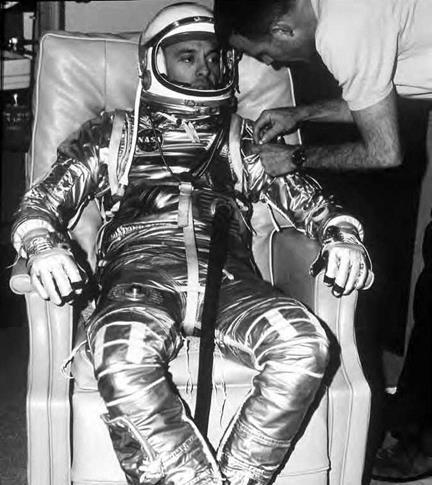
These unique experimental rocket-propelled aircraft, devel­oped and flown from 1946 through 1968, were instrumental in helping scientists understand how best to sustain human life dur­ing high-speed, high-altitude flight.[329] One of the more important human factors developments employed in the first of this series, the Bell X-1 rocket plane, was the T-1 partial pressure suit designed by Dr. James Henry of the University of Southern California and produced by the David Clark Company.[330] This suit proved its worth during an August 25, 1949, test flight, when X-1 pilot Maj. Frank K. "Pete” Everest lost cabin pressure at an altitude of more than 65,000 feet. His pressure suit automatically inflated, and though it constricted him almost to the point of incapacitation, it nevertheless kept him alive until he could descend. He thus became the first pilot saved by the emergency use of a pressure suit.[331]

During the 1950s and 1960s, the NACA and NASA tested several additional experimental rocket planes after the X-1 series; however, the most famous and accomplished of these by far was the North American X-15. During the 199 flights this phenomenal rocket plane made from 1959 to 1968, it carried its pilots to unprecedented hypersonic speeds of nearly 7 times the speed of sound (4,520 mph) and as high as 67 miles above the Earth.[332] The wealth of information these flights continued to produce, nearly right up until the first piloted Moon flight, enabled tech­nology vital to the success of the NASA piloted space program.

One of the X-15 program’s more important challenges was how to keep its pilots alive and functioning in a craft traveling through space at hypersonic speeds. The solution was the development of a full – pressure suit capable of sustaining its occupant in the vacuum of space yet allowing him sufficient mobility to perform his duties. This innova­tion was an absolute must before human space flight could occur.

The MC-2 full-pressure suit provided by the David Clark Co. met these requirements, and more.[333] The suit in its later forms, the A/P-22S-2 and A/P-22S-6, not only provided life-sustaining atmospheric pressure, breathable oxygen, temperature control, and ventilation, but also a para­chute harness, communications system, electrical leads for physiolog­ical monitoring, and an antifogging system for the visor. Even with all these features, the pilot still had enough mobility to function inside the aircraft. By combining the properties of this pressure suit with those of the X-15 ejection seat, the pilot at least had a chance for emergency escape from the aircraft. This suit was so successful that it was also adapted for use in high-altitude military aircraft, and it served as the template for the suit developed by B. F. Goodrich for the Mercury and Gemini piloted space programs.[334]

The development of a practical spacesuit was not the only human factors contribution of the X-15 program. Its pioneering emphasis on the physiological monitoring of the pilot also formed the basis of that used in the piloted space program. These in-flight measurements and later analysis were an important aspect of each X-15 flight. The aero – medical data collected included heart and respiratory rates, electrocardio­graph, skin temperature, oxygen flow, suit pressure, and blood pressure.

The Jet Age: Man Reaches the Edge of Space

The X-15 on lakebed with B-52 mother ship flying overhead. Lessons learned from this phenom­enal rocket plane helped launch humans into space. NASA.

Through this information, researchers were able to better under­stand human adaptation to hypersonic high-altitude flight.[335]

The many lessons learned from these high-performance rocket planes were invaluable in transforming space flight into reality. From a human factors standpoint, these flights provided the necessary testbed for ush­ering humans into the deadly environment of high-altitude, high-speed flight—and ultimately, into space.

Another hazardous type of human research activity conducted after World War II that contributed to piloted space operations was the series of U. S. military piloted high-altitude balloon flights conducted in the 1950s and 1960s. Most significant among these were the U. S. Navy Strato – Lab flights and the Air Force Manhigh and Excelsior programs.[336]

The information these flights provided paved the way for the design of space capsules and astronaut pressure suits, and they gained impor­tant biomedical and astronomical data.

The Excelsior program, in particular, studied the problem of emer­gency egress high in the stratosphere. During the flight of August 16, 1960, Air Force pilot Joseph Kittinger, Jr., ascended in Excelsior III to an altitude of 102,800 feet before parachuting to Earth. During this highest-ever jump, Kittinger went into a freefall for a record 4 minutes 36 seconds and attained a record speed for a falling human body out­side of an aircraft of 614 mph.[337] Although, thankfully, no astronaut has had to repeat this performance, Kittinger showed how it could be done.

Yet another human research contribution from this period that proved to be of great value to the piloted space program was the series of impact deceleration tests conducted by U. S. Air Force physician Lt. Col. John P. Stapp. While strapped to a rocket-propelled research sled on a 3,500-foot track at Holloman Air Force Base (AFB), NM, Stapp made 29 sled rides during the years of 1947-1954. During these, he attained speeds of up to 632 mph, making him—at least in the eyes of the press— the fastest man on Earth, and he withstood impact deceleration forces of as high as 46 times the force of gravity. To say this work was haz­ardous would be an understatement. While conducting this research, Stapp suffered broken bones, concussions, bruises, retinal hemorrhages, and even temporary blindness. But the knowledge he gained about the effects of acceleration and deceleration forces was invaluable in delin­eating the human limitations that astronauts would have while exiting and reentering the Earth’s atmosphere.[338]

All of these flying and research endeavors involved great danger for the humans directly involved in them. Injuries and fatalities did occur, but such was the dedication of pioneers such as Stapp and the pilots of these trailblazing aircraft. The knowledge they gained by putting their lives on the line—knowledge that could have been acquired in no other way—would be essential to the establishment of the piloted space pro­gram, looming just over the horizon.

Advanced Air Transportation Technologies Program

NASA established this project in 1996 to increase the capability of the Nation’s air transport activities. This program’s specific goal was to develop a set of "decision support tools” that would help air traffic service providers, aircrew members, and airline operations centers in streamlining gate-to-gate operations throughout the NAS.[431] Project personnel were tasked with researching and developing advanced

Advanced Air Transportation Technologies Program

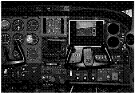
NASA’s Boeing 737 in 1987 after significant cockpit upgrades. Note its much more user-friendly "glass cockpit” display, featuring eight 8- by 8-inch color monitors. NASA.

concepts within the air traffic management system to the point where the FAA and the air transport industry could develop a preproduction prototype. The program ended in 2004, but implementation of these tools into the NAS addressed such air traffic management challenges as complex airspace operations and assigning air and ground responsi­bilities for aircraft separation. Several of the technologies developed by this program received "Turning Goals into Reality” awards, and some of these—for example, the traffic management adviser and the collab­orative arrival planner—are in use by ATC and the airlines.[432]

Glimpse of the Future: Advanced Civil Aircraft

Most of the free-flight model research conducted by NASA to evaluate dynamic stability and control within the flight envelope has focused on military configurations and a few radical civil aviation designs. This sit­uation resulted from advances in the state of the art for design methods for conventional subsonic configurations over the years and many expe­riences correlating results of model and airplane tests. As a result, trans­port design teams have collected massive data and experience bases for transports that serve as the corporate knowledge base for derivative air­craft. For example, companies now have considerable experience with the accuracy of their conventional static wind tunnel model tests for the prediction of full-scale aircraft characteristics, including the effects of Reynolds number. Consequently, testing techniques such as free-flight tests do not have high technical priority for such organizations.

The radical Blended Wing-Body (BWB) flying wing configuration has been a notable exception to the foregoing trend. Initiated with NASA sponsorship at McDonnell-Douglas (now Boeing) in 1993, the subsonic BWB concept carries passengers or payload within its wing structure to minimize drag and maximize aerodynamic efficiency.[503] Over the past 16 years, wind tunnel research and computational studies of various BWB configurations have been conducted by NASA-Boeing teams to assess cruise conditions at high subsonic speeds, takeoff and landing charac­teristics, spinning and tumbling tendencies, emergency spin/tumble recovery parachute systems, and dynamic stability and control.

By 2005, the BWB team had conducted static and dynamic force tests of models in the 12-Foot Low-Speed Tunnel and the 14- by 22-Foot Tunnel to define aerodynamic data used to develop control laws and con­trol limits, as well as trade studies of various control effectors available

on the trailing edge of the wing. Free-flight testing then occurred in the Full-Scale Tunnel with a 12-foot-span model.[504] Results of the flight test indicated satisfactory flight behavior, including assessments of engine – out asymmetric thrust conditions.

In 2002, Boeing contracted with Cranfield Aerospace, Ltd., for the design and production of a pair of 21-foot-span remotely piloted models of BWB vehicles known as the X-48B configuration. After con­ventional wind tunnel tests of the first X-48B vehicle in the Langley Full – Scale Tunnel in 2006, the second X-48B underwent its first flight in July 2007 at the Dryden Flight Research Center. The BWB flight-test team is a cooperative venture between NASA, Boeing Phantom Works, and the Air Force Research Laboratory. The first 11 flight tests of the 8.5- percent-scale vehicle in 2007 focused on low-speed dynamic stability and control with wing leading-edge slats deployed. In a second series of flights, which began in April 2008, the slats were retracted, and higher speed studies were conducted. Powered by three model aircraft turbojet engines, the 500-pound X-48B is expected to have a top speed of about 140 mph. A sequence of flight phases is scheduled for the X-48B with various objectives within each study directed at the technology issues facing the implementation of the innovative concept.

The Anatomy of a Wind Tunnel

The design of an efficient aircraft or spacecraft involves the use of the wind tunnel. These tools simulate flight conditions, including Mach num­ber and scale effects, in a controlled environment. Over the late 19th, 20th, and early 21st centuries, wind tunnels evolved greatly, but they all incorporate five basic features, often in radically different forms. The main components are a drive system, a controlled fluid flow, a test sec­tion, a model, and instrumentation. The drive system creates a fluid flow that replicates flight conditions in the test section. That flow can move at subsonic (up to Mach 1), transonic (Mach 0.75 to 1.25), supersonic (up to Mach 5), or hypersonic (above Mach 5) speeds. The placement of a scale model of an aircraft or spacecraft in the test section via balances allows the measurement of the physical forces acting upon that model with test instrumentation. The specific characteristics of each of these compo­nents vary from tunnel to tunnel and reflect the myriad of needs for this testing technology and the times in which experimenters designed them.[529]

Wind tunnels allow researchers to focus on isolating and gather­ing data about particular design challenges rooted in the four main systems of aircraft: aerodynamics, control, structures, and propulsion. Wind tunnels measure primarily forces such as lift, drag, and pitching moment, but they also gauge air pressure, flow, density, and tempera­ture. Engineers convert those measurements into aerodynamic data to evaluate performance and design and to verify performance predic­tions. The data represent design factors such as structural loading and strength, stability and control, the design of wings and other elements, and, most importantly, overall vehicle performance.[530]

Most NACA and NASA wind tunnels are identified by their location, the size of their test section, the speed of the fluid flow, and the main design characteristic. For example, the Langley 0.3-Meter Transonic

Cryogenic Tunnel evaluates scale models in its 0.3-meter test section between speeds of Mach 0.2 to 1.25 in a fluid flow of nitrogen gas. A spe­cific application, 9- by 6-Foot Thermal Structures Tunnel, or the exact nature of the test medium, 8-Foot Transonic Pressure Tunnel, can be other characterizing factors for the name of a wind tunnel.