Category NASA’S CONTRIBUTIONS TO AERONAUTICS

Modern Composite Airplane

Stephen Trimble

Structures and structural materials have undergone progressive refine­ment. Originally, aircraft were fabricated much like ships and complex wooden musical instruments: of wood, wire, and cloth. Then, metal gradually supplanted these materials. Now, high-strength compos­ite materials have become the next generation, allowing for synthetic structures with even better structural properties for much less weight. NASA has assiduously pursued development of composite structures.

HEN THE LOCKHEED MARTIN X-55 advanced composite cargo aircraft (ACCA) took flight early on the morning of June 2, 2009,[642] it marked a watershed moment in a century-long quest to marry the high-strength yet lightweight properties of plastics with the structure required to support a heavily loaded flying vehicle. As the X-55, a greatly modified Dornier 328Jet, headed east from the runway at the U. S. Air Force’s Plant 42 outside Palmdale, CA, it gave the appear­ance of a conventional cargo aircraft. But the X-55’s fuselage structure aft of the fuselage represented perhaps the promising breakthrough in four decades of composite technology development.

The single barrel, measuring 55 feet long by 9 feet wide,[643] revolu­tionizes expectations for structural performance at the same time that it proposes to dramatically reduce manufacturing costs. In the long his­tory of applying composites to aircraft structures, the former seemed always to come at the expense of the latter, or vice versa. Yet the X-55 defies experience, with both aluminum skins and traditional compos­ites. To distinguish it from the aluminum skin of the 328Jet, Lockheed used fewer than 4,000 fasteners to assemble the aircraft with the single­

piece fuselage barrel. The metal 328Jet requires nearly 30,000 fasteners for all the pieces to fit together.[644] Unlike traditional composites, the X-55 did not require hours of time baking in a complex and costly industrial oven called an autoclave. Neither was the X-55 skin fashioned from tex­tile preforms with resins requiring a strictly controlled climate that can be manipulated only within a precise window of time. Instead, Lockheed relied on an advanced composite resin called MTM45-1, an "out – of-autoclave” material flexible enough to assemble on a production line yet strong enough to support the X-55’s normal aerodynamic loads and payload of three 463L-standard cargo pallets.[645]

Modern Composite AirplaneLockheed attributed the program’s success to the fruits of a 10-year program sponsored by the Air Force Research Laboratory called the composites affordability initiative.[646] In truth, the X-55 bears the legacy of nearly a century’s effort to make plastic suitable in terms of both per­formance and cost for serving as a load-bearing structure for large mil­itary and commercial aircraft.

It was an effort that began almost as soon as a method to mass – produce plastic became viable within 4 years after the Wright brothers’ first flight in 1903. In aviation’s formative years, plastics spread from cockpit dials to propellers to the laminated wood that formed the fuse­lage structure for small aircraft. Several decades would pass, however, before the properties of all but the most advanced plastics could be con­sidered for mainstream aerospace applications. The spike in fuel prices of the early 1970s accelerated the search for a basic construction mate­rial for aircraft more efficient than aluminum, and composites finally moved to the forefront. Just as the National Advisory Committee for Aeronautics (NACA) fueled the industry’s transition from spruce to metal in the early 1930s, the National Aeronautics and Space Administration (NASA) would pioneer the progression from all-metal airframes to all­composite material over four decades.

The first flight of the X-55 moved the progression of composite tech­nology one step further. As a reward, the Air Force Research Laboratory announced 4 months later that it would continue to support the X-55
program, injecting more funding to continue a series of flight tests.[647] Where the X-55 technology goes from here can only be guessed.

Avionics and Cockpit Research for Safer General Aviation Operations

Aircraft instrumentation has always been intrinsically related to flight safety. The challenge of blind and bad-weather flying in the 1920s led to development of both radio navigation equipment and tech­niques, and specialized blind-flying instrumentation, typified by the gyro-stabilized artificial horizon, which, like radar later, was one of the few truly transforming instruments developed in the history of flight, for it made possible instrument-only (IFR) flight. Taken together with advances in the Federal airway system, the development of lightweight airborne radars, digital electronics, sophisticated communications, and radar-based and later satellite navigation, as well as access to up-to-date weather information, revolutionized civil and military air operations. Ironically, accident rates remained high, particularly among GA pilots flying single-pilot (SP) aircraft under IFR conditions. By the early 1980s, the National Transportation Safety Board was reporting that "SPIFR” accidents accounted for 79 percent of all IFR-related accidents, with half of these occurring during high-workload landing approaches, total­ing more than 100 serious accidents attributable to pilot error per year.[858] Analysis revealed five major problem areas: controller judgment and response, pilot judgment and response, Air Traffic Control (ATC) intra­facility and interfacility conflict, ATC-pilot communication, and IFR – VFR (instrument flight rules-visual flight rules) conflicts. Common to
all of these were a mix of human error, communications deficiencies, conflicting or complex procedures and rules, and excessive workload. In particular, NASA researchers concluded that "methods, techniques, and systems for reducing work load are drastically needed.”[859]

In the mid-1970s, NASA aeronautics planners had identified "design[ing] avionic systems to more effectively integrate the light air­plane with the air-space system” as a priority, with researchers at Ames Research Center evaluating integration avionic functions with the goal of producing a single system concept.[860] In 1978, faced with the challenge of rising SPIFR accidents, NASA Langley Research Center launched a SPIFR program, holding a workshop in August 1983 at Langley to review and evaluate the progress to date on SPIFR studies and to dis­seminate it to an industry, academic, and governmental audience. The SPIFR program studied in depth the interface of the pilot and airplane, looking at a variety of issues ranging from the tradeoffs between com­plex autopilots and their potential benefits to simulator utility. Overall, researchers found that "[b]ecause of the increase in air traffic and the more sophisticated and complex ground control systems handling this traffic, IFR flight has become extremely demanding, frequently tax­ing the pilot to his limits. It is rapidly becoming imperative that all the pilot’s sensory and manipulative skills be optimized in managing the air­craft systems”; hopefully, they reasoned, the rapid growth in computer capabilities could "enhance single-crewman effectiveness in future air­craft operations and automated ATC systems.”[861] Encouragingly, in part because of NASA research, a remarkable 41-percent decrease in overall GA accidents did occur from the mid-1980s to the late 1990s.[862]

However, all was not well. Indeed, a key goad stimulating NASA’s pur­suit of avionics technology to enhance flight safety (particularly weather safety) was the decline of American General Aviation. In the late 1970s, America’s GA aircraft industry reached the peak of its power: in 1978, manufacturers shipped 17,817 aircraft, and the next year, 1979, the top three manufacturers—Cessna, Beech, and Gates Learjet—had combined sales over $1.8 billion. It seemed poised for even greater success over the next decade. In fact, such did not occur, thanks largely to rapidly rising insurance costs added to aircraft purchase prices, a by-product of a "rash of product liability lawsuits against manufacturers stem­ming from aircraft accidents,” some frivolously alleging inherent design flaws in aircraft that had flown safely for previous decades. Rising air­craft prices cooled any ardor for new aircraft purchases, particularly of single-engine light aircraft (business aircraft sales were affected, but more slowly). Other factors also contributed, including a global reces­sion in the early 1980s, an increase in aircraft leasing and charter aircraft operations (lessening the need for personal ownership), and mergers within the aircraft industry that eliminated some production programs. The number of students taking flight instruction fell by over a third, from 150,000 in 1980 to 96,000 in 1994. That year, GA manufacturers produced just 928 aircraft, representing a production decline of almost 95 percent since the heady days of the late 1970s.[863]

The year 1994 witnessed both the near-extinction of American General Aviation and its fortuitous revival. At the nadir of its fortunes, relief, fortunately, was in hand, thanks to two initiatives launched by Congress and NASA. The first was the General Aviation Revitalization Act (GARA) of 1994, passed by Congress and signed into law in August that year by President William Jefferson Clinton.[864] GARA banned prod­uct liability claims against manufacturers later than 18 years after an aircraft or component first flew. By 1998, the 18-year provision could be applied to the large numbers of aircraft produced in the 1970s, bring­ing relief at last to manufacturers who had been so plagued by legal action that many had actually taken aircraft—including old classics such as the Cessna C-172—out of production.[865] It is not too strong to state that GARA saved the American GA industry from utter extinction, for it brought much needed stability and restored sanity to a litigation process that had gotten out of hand. Thus it constitutes the most signif­icant piece of American aviation legislation passed in the modern era.

But important as well was a second initiative, the establishment by NASA of the AGATE program, a joint NASA-industry-FAA partnership. AGATE existed thanks to the persistency of Bruce Holmes, the Agency’s Assistant Director of Aeronautics, who had vigorously championed it. Functionally organized within NASA’s Advanced Subsonic Technology Project Office, AGATE dovetailed nicely with GARA. It sought to revi­talize GA by focusing on innovative cockpit technologies that could achieve goals of safety, affordability, and ease of use, chief of which was the "Highway in the Sky” (HITS) initiative, which aimed to replace the dial-and-gauge legacy instrument technology of the 1920s with advanced computer-based graphical presentations. As well, it supported crashwor­thiness research. It served as well as single focal point to bring together NASA, industry, Government, and GA community representatives.

AGATE ran from 1994 through 2001, and a key aspect of its success was that it operated under a NASA-unique process, the Joint Sponsored Research Agreement (JSRA), a management process that streamlined research and internal management processes, while accelerating the results of technology development into the private sector. AGATE suf­fered in its early years from "learning problems” with internal communi­cation, with building trust and openness among industry partners more used to seeing themselves as competitors, and with managerial over­sight of its activities. Some participants were disappointed that AGATE never achieved its most ambitious objective, a fully automated aircraft. Others were bothered by the uncertainty of steady Federal support, a characteristic aspect of Federal management of research and develop­ment. But if not perfect—and no program ever is—AGATE proved vital to restoring GA, and as an end-of-project study concluded inelegantly if bluntly, "[a]ccording to participants from all parts of the program, AGATE revitalized an industry that had gone into the toilet.”[866]

The legacy of AGATE is evident in much of NASA’s subsequent avi­onics and cockpit presentation research, which, building upon earlier research, has involved improving a pilot’s situational awareness. Since weather-related accidents account for one-third of all aviation accidents and over one-quarter of all GA accidents, a particular concern is present­ing timely and informative weather information, for example, graphics overlaid on navigational and geographical cockpit displays.[867] Another area of acute interest is improving pilot controllability via advanced flight control technology to close the gap between an automobile-like 2-D control system and the traditionally more complex 3-D aircraft sys­tem and generating a HITS-like synthetic vision capability to enhance flight safety. This, too, is a longstanding concern, related to the handling qualities and flight control capabilities of aircraft so that the pilot can concentrate more on what is going on around the aircraft than having to concentrate on flying it.[868]

Models and Mother Ships—Utility RPRV and Ultralight RPRV

By the mid-1990s, it was clear to NASA researchers that use of unpiloted vehicles for research and operational purposes was expanding dramat­ically. R. Dale Reed and others at Dryden proposed development of in­house, hands-on expertise in flight-testing experimental UAVs to guide and support anticipated research projects. They suggested that lower risks and higher mission-success rates could be achieved by applying les­sons learned from flight-test experience and crew training. Additionally, they recommended that special attention be paid to human factors by standardizing ground control consoles and UAV operational procedures.

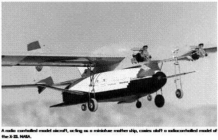
To meet these goals, Reed recommended using two types of low – cost expendable UAVs. The first was a radio-controlled model air­plane weighing less than 50 pounds but capable of carrying miniature downlink television cameras, autopilot, and GPS guidance systems. Requirements for flight termination systems and control redundancy for such an aircraft would be much less stringent than those for larger UAVs, and the model would require much less airspace for flight oper­ations. Reed felt the R/C model could serve as a basic trainer for UAV pilots because the same skills and knowledge are required regardless of vehicle size. Additionally, the R/C model could provide flight research results at very low cost.[998] Second, Reed felt the modified Rans S-12 ("Ye Better Duck”) should be returned to flight status since an ultra­light-type vehicle could duplicate the size and flying characteristics of planned high-altitude RPRVs then being developed. He saw the S-12 as an advanced trainer for NASA UAV crews. The S-12 had not been flown since January 1994 and required a thorough inspection of airframe and engine, as well as replacement of batteries in several of its sys­tems. Reed recommended that Tony Frackowiak of the Dryden Physics Lab be given the task of preparing the "Ye Better Duck” for flight sta­tus and then serving as primary checkout pilot.[999] Reed submitted his proposals to Dryden director Ken Szalai with a recommendation to develop a Utility UAV as a mother ship for small experimental models. Jenny Baer-Riedhart and John Del Frate, Project Manager and Assistant Project Manager, respectively, for the Environmental Research Aircraft and Sensor Technology (ERAST) program, were willing to support the project plan if the Dryden Operations Division provided a require­ment and also pledged strong support for the plan. Research pilots Dana Purifoy, Tom McMurtry, and Steve Ishmael were enthusiastic about the project. Ishmael immediately saw a potential application for the Utility UAV to drop a subscale aerodynamic model of the planned X-33 spacecraft. Project personnel included Reed as Utility UAV project engi­neer, research pilot Purifoy, crew chief/project pilot Tony Frackowiak, UAV systems technician Howard Trent, and UAV backup pilot Jerry Budd.[1000] [1001]

During this time, Reed reactivated the old R/C Mothership that had been used to launch lifting body models in the 1960s. Frackowiak removed and overhauled its engines, cleaned the exhaust system, replaced throttle servos, and made other repairs. During six checkout flights November 25, 1996, the Mothership underwent checkout and demonstrated a 20-pound payload capability. It was subsequently used as a launch air­craft for a model of a hypersonic wave rider and a 5-percent-scale model of the Pegasus satellite booster.123 Meanwhile, Reed had pressed on with plans for the larger Utility UAV. For systems development, Frackowiak acquired a Tower Hobbies Trainer-60 R/C model and modified it to accept several different gyro and autopilot configurations. The Trainer 60 was 57 inches long, had a 69-inch wingspan, and weighed just 8 pounds. Frackowiak conducted more than a dozen test flights with the model in March 1997.[1002] In April 1997, the Mothership was equipped with a video camera and telemetry system that would also be used on the Utility UAV. The first three test flights took place at Rosamond Dry Lake on the morning of April 10, with one pilot inside a control van watching a video monitor and another outside directly observing the aircraft. For the first flight, Frackowiak served as outside pilot—controlling takeoff and landing—while Reed familiarized himself with pitch and roll angles in climb, cruise, and descent. On the third flight, they switched positions so Reed could make a low approach to familiarize Frackowiak with the view from the camera. They found that it helped to have a ground mark­ing (such as a runway edge stripe) on the lakebed as a visual reference during touchdown. Other areas for improvement included the reduc­tion of glare on the video monitor, better uplink antenna orientation, and stabilization of pitch and roll rate gyros to help less-experienced pilots more easily gain proficiency.[1003] In May 1997, Dana Purifoy began familiarization and training with the Mothership. In August, the air­craft was again used to launch the Pegasus model (for deep-stall tests) as well as a Boeing-UCLA Solar-Powered Formation Flight (SPFF) vehicle.

Подпись: A radio controlled model aircraft, acting as a miniature mother ship, carries aloft a radiocontrolled model of the X-33. NASA. Подпись: 9

On August 5, Reed piloted the Mothership, while Frackowiak flew the SPFF model.

In September 1997, Frackowiak modified the Mothership’s launch hook to accept a scale model of the Lockheed Martin X-33 lifting body vehicle. The X-33 Mini-RPRV was, like the SPFF model, equipped with its own set of radio controls. Initial drop flights took place September 30 at a sod farm near Palmdale, with John Howell piloting the X-33 model.

Following a series of SPFF flights in October, the Mothership was taken to Air Force Plant 42 in Palmdale for more X-33 Mini-RPRV drops. On February 12, 1998, interference led to loss of control. The Mothership crashed, sustaining severe but repairable damage to wing and nose.[1004]

While the Mothership was undergoing repairs, Frackowiak com­pleted construction of the 30-pound Utility UAV in April 1998. On April 24, he took the airplane to Tailwinds Field, a popular R/C model airstrip in Lancaster, for its first flight. Takeoff at partial power was uneventful. After gaining 300 feet altitude, Frackowiak applied full power to check the trim then checked controllability in slow flight before bringing the Utility UAV in for a smooth landing.

By the end of June, the aircraft had been cleared to carry payloads weighing up to 20 pounds. Three months later, the Utility UAV was

modified to carry the X-33 Mini-RPRV. On September 10, Reed and John Redman began a series of captive flights at Rosamond Dry Lake. Drop testing at Rosamond began 4 days later, with 4 successful free flights made over a 2-day span to evaluate higher X-33 model weights and a dummy nose boom.[1005] On October 1, 1998, the Utility UAV made its 20th flight, and the X-33 model was released for the 5th time at Rosamond. Piloted by Frackowiak, the lifting body’s steep descent ended with a flaw­less landing, but disaster lurked in wait for the drop plane. As Redman maneuvered the Utility UAV toward final approach, he watched it sud­denly roll to the left and plunge into the clay surface of the lakebed, sus­taining major damage.[1006] Further testing of the X-33 Mini-RPRV was undertaken using the repaired Mothership. Several successful drops were made in early October, as well as a familiarization flight for research pilot Mark Stucky. Reed noted in his log: "The Mothership has again proven the practicality of its design, as it has been flawless during these launches. And it is very good to see it flying and performing useful missions again.”[1007]

The American SST Program: Competition, Selection, and Demise

NASA participated extensively in plans to develop an American SST. President Kennedy had committed the U. S. Government to contrib­ute funding for 7 5 percent of the aircraft’s development cost, with a $1-billion upper limit. Industry would contribute the rest of the cost, with the Government money to be repaid via royalty payments as air­craft were sold. This Government backing was a response to the 1962 announcement of a joint government-backed program between France (Sud Aviation) and England (British Aircraft Corporation) companies to develop a Mach 2.2, 100-passenger transport, which emerged as the graceful Concorde. The FAA, NASA, and the Department of Defense would manage the American program and select a final contractor to make the SST a reality.[1092] The competition aspect of the program gained even more of a Cold War aspect when the Soviet Union announced in June 1965 that it also was developing a Mach 2.2 SST, which would fly in 1968. The United States was still deciding on a contractor and design to be given the go-ahead.

Подпись: Desktop models of American Boeing and Lockheed SST finalist designs. William Flanagan. Подпись: 10

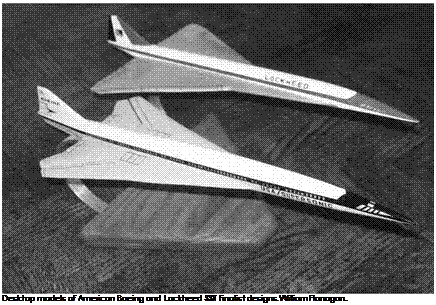
The finalist contractors selected in May 1964 were Lockheed and Boeing, after rival Douglas and NAA designs (the latter based on B-70 technology) were eliminated. Although the initial submissions had a speed requirement of Mach 2.2+ with 160 passengers, the selected ini­tial designs were a double delta Lockheed Model 2000 Mach 3 aircraft and a Boeing Model 733 Mach 2.7 variable sweep aircraft reminiscent of the NASA SCAT 16 design. Both finalist contractors had done anal­yses of the NASA SCAT designs in 1963. They had reached the conclu­sion that at Mach 2.2, the range specification could not be achieved, so they opted for the higher Mach cruises. FAA Administrator Najeeb Halaby had favored the higher cruise speed with larger capacity to pre­empt the Concorde in the international airliner marketplace. General Electric and Pratt & Whitney were the engine contractors chosen to develop engines for the SST. Both had developed 30,000-pound thrust engines for supersonic cruise airplanes (GE J93 for the XB-70 and Pratt & Whitney J58 for the A-12/SR-71), but the SST would require four 60,000-pound thrust engines.

The selection was announced on the last day of 1966. The Lockheed configuration had remained relatively unchanged, while the Boeing fuse­lage had been made longer and the engine position had shifted from under the wing to under the tail. Even the name had been changed, to

Boeing 2707. Both contractors built impressive full-scale mockups that were as much publicity props as engineering tools. (Unfortunately, the impressive mockups would prove to be the only airplanes built.) With fuselage lengths around 300 feet to accommodate up to 300 passengers and the fuel for ranges of over 3,000 miles, the mockups represented a new dawn in civil aviation. But the Boeing design and the Pratt & Whitney engine were chosen as the United States’ entry in the super­sonic airliner derby. (Details of the Boeing design showed that the vari­able sweep wing was unachievable because of weight and complexity; the Boeing design had 59 control surfaces, versus the Lockheed design’s 16). Eventually, the Boeing design evolved to a fixed double delta with a small horizontal tail and four underwing engine nacelles with axisym- metric inlets. American flag carriers placed $100,000 deposits to reserve delivery positions on the production line with an order book of 120 air­craft by 1969, and work began on the first prototype.[1093]

Baby, It’s Cold Out There

Not surprisingly, ice buildup on aircraft is bad. If it happens on the ground, then pilots and passengers alike must wait for the ice to be removed, often with hazardous chemicals and usually resulting in flight delays that can trigger a chain reaction of schedule problems across the Nation’s air system. If an aircraft accumulates ice in the air, depend­ing on the severity of the situation, the results could range from mild annoyance that a de-icing switch has to be thrown to complete aero­dynamic failure of the wing, accompanied by total loss of control, a spiraling dive from high altitude, a premature termination of the flight and all lives on board, followed by the reward of becoming the lead item on the evening news.

Icing is a problem for flying aircraft not so much because of the added weight, but because of the way even a tiny amount of ice can begin to disrupt the smooth airflow over the wings, wreaking havoc with the wing’s ability to generate lift and increasing the amount of drag, which
slows the aircraft and pitches the nose down. This prompts the pilot to pull the nose up to compensate for the lost lift, which allows even more ice to build up on the lower surface of the wing. And the vicious circle continues, potentially leading to disaster. Complicating the matter is that even with options for clearing the wing of ice—discussed shortly— ice buildup can remain and/or continue on other aircraft surfaces such as antennas, windshields, wing struts, fixed landing gear, and other pro­trusions, all of which can still account for a 50-percent increase in drag even if the wing is clean.[1218]

Подпись: 12From the earliest experience with icing during the 1920s and on through the present day, researchers have observed and understood there to be three primary categories of aircraft ice: clear, rime, and mixed. Each one forms for slightly different reasons and exhibits certain prop­erties that influence the effectiveness of available de-icing measures.[1219]

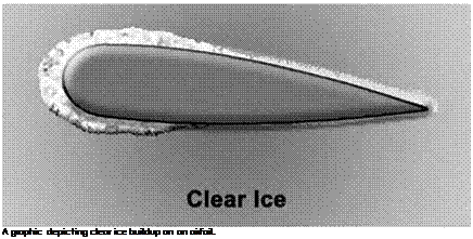
Clear ice is usually associated with freezing rain or a special cate­gory of rain that falls through a region of the atmosphere where tem­peratures are far below the normal freezing point of water, yet the drops remain in a liquid state. These are called super-cooled drops.

Подпись: A graphic depicting clear ice buildup on an airfoil.

Such drops are very unstable and need very little encouragement to freeze. When they strike a cold airframe they begin to freeze, but it is

not an instant process. The raindrop freezes as it spreads out and con­tinues to make contact with an aircraft surface whose skin temperature is at or below 32 degrees Fahrenheit (0 degrees Celsius). The slower the drop freezes, the more time it will have to spread out evenly and create a sheet of solid, clear ice that has very little air enclosed within. This flow – back phenomenon is greatest at temperatures right at freezing. Because of its smooth surface, clear ice can quickly disrupt the wing’s ability to generate lift by ruining the wing’s aerodynamic shape. This type of ice is quite solid in the sense that if any of it does happen to loosen or break off, it tends to come off in large pieces that have the ability to strike another part of the aircraft and damage it.[1220]

Подпись: 12

Подпись: A graphic depicting rime ice buildup on an airfoil.

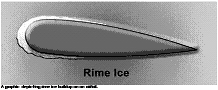
Rime ice proves size makes a difference. In this case the super­cooled liquid water drops are smaller than the type that produces

clear ice. When these tiny drops of water strike a cold aircraft surface, most of the liquid drops instantly freeze and any water remaining is not enough to create a sheet of ice. Instead, the result is a brittle ice that looks milky white, is opaque, has a rough surface due to its makeup of ice crystals and trapped air, and doesn’t accumulate as quickly as clear ice. It does not weigh as much, either, and tends to stick to the leading edge of the wing and the cowl of the engine intakes on a jet, making rime ice just as harmful to the airflow and aerodynamics of the aircraft.[1221]

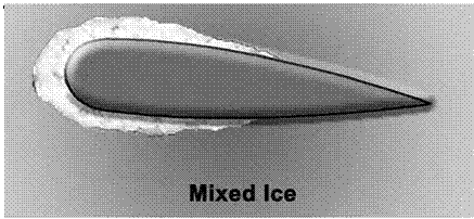
Naturally, when an aircraft encounters water droplets of various sizes, a combination of both clear and rime ice can form, creating the

Подпись: 12 Baby, It's Cold Out There

third category of icing called mixed ice. The majority of ice encountered in aviation is of this mixed type.[1222]

Aircraft must also contend with snow, avoiding the wet, sticky stuff that makes great snowballs on the ground but in the air can quickly accu­mulate not only on the wings—like ice, a hazard in terms of aerodynam­ics and weight—but also on the windshield, obscuring the pilot’s view despite the best efforts of the windshield wipers, which can be rendered useless in this type of snow. And on the ground, frost can completely cover an aircraft that sits out overnight when there is a combination of humid air and subfreezing temperatures. Frost can also form in certain flying conditions, although it is not as hazardous as any of the ices.[1223]

Revelation and Call to Action

Подпись: 13During the Vietnam conflict, U. S. pilots flying F-4 and F-105 aircraft faced highly maneuverable MiG-17 and MiG-19 aircraft, and the unan­ticipated return of the close-in dogfight demanded maneuverability that had not been required during design and initial entry of the U. S. aircraft into operational service. Unfortunately, aircraft such as the F-4 exhibited a marked deterioration in lateral-directional stability and control char­acteristics at high angles of attack. Inadvertent loss of control became a major issue, with an alarming number of losses in training accidents. A request for support to the NASA Langley Research Center by representa­tives of the Air Force Aeronautical Systems Division in 1967 resulted in an extensive analysis of the high-angle-of-attack deficiencies of the air­craft and wind tunnel, free-flight model, and piloted simulator studies.[1284]

The F-4 experience is especially noteworthy in NASA’s contributions to high-angle-of-attack technology. Based on the successful demonstra­tions of analysis and design tools by NASA, management within the Air Force, Navy, and NASA strongly supported an active participation by the Agency in high-angle-of-attack technology, resulting in requests for simi­lar NASA involvement in virtually all subsequent DOD high-performance aircraft development programs, which continue to the current day. After the F-4 program, NASA activities at Langley were no longer limited to spin tunnel tests but included conventional and special dynamic wind tunnel tests, analytical studies, and piloted simulator studies.

The shocking number of losses of F-4 aircraft and aircrews did not, however, escape the attention of senior Air Force leadership. As F-4 stall/spin/out-of-control accidents began to escalate, other aircraft types were also experiencing losses, including the A-7, F-100, and F-111. The situation reached a new level of concern when, on April 26, 1971, Air Force Assistant Secretary for Research and Development (R&D) Grant

L. Hansen sent a memorandum to R&D planners within the Air Force noting that during a 5-year period from 1966 through 1970, the service had lost over $200 million in assets in stall/spin/out-of-control accidents while it had spent only $200,000 in R&D.[1285] Hansen’s memo called for a broad integrated research program to advance the state of the art with an emphasis on "preventing the loss of, rather than recovering, aircraft control.” The response of Air Force planners was swift, and in December 1971, a major symposium on stall/poststall/spin technology was held at Wright-Patterson Air Force Base.[1286] Presentations at the symposium by Air Force, Navy, and Army participants disclosed that the number of aircraft lost by the combined services to stall/spin/out-of-control acci­dents during the subject 5-year period was sobering: over 225 aircraft valued at more than $367 million. Some of the aircraft types stood out as especially susceptible to this type of accident—for example, the Air Force, Navy, and Marines had lost over 100 F-4 aircraft in that period.

Подпись: 13An additional concern was that valuable test and evaluation (T&E) aircraft and aircrews were being lost in flight accidents during high – angle-of-attack and spin assessments. At the time of the symposium, the Navy had lost two F-4 spin-test aircraft and an EA-6B spin-test vehi­cle, and the Air Force had lost an F-4 and F-111 during spin-test pro­grams because of unrecoverable spins, malfunctions of emergency spin parachute systems, pilot disorientation, and other spin-related causes. The T&E losses were especially distressing because they were experi­enced under controlled conditions with a briefed pilot entering carefully planned maneuvers with active emergency recovery systems.

The 1971 symposium marked a new waypoint for national R&D efforts in high-angle-of-attack technology. Spin prevention became a major focus of research, the military services acknowledged the need for controlled flight at high-angle-of-attack conditions, and DOD formally
stated high-angle-of-attack and maneuverability requirements for new high-performance aircraft programs. Collaborative planning between industry, DOD, and NASA intensified for research efforts, including ground-based and flight activities.[1287] The joint programs clearly acknowl­edged the NASA role as a source of corporate knowledge and provider of national facilities for the tasks. With NASA having such responsibilities in a national program, its research efforts received significantly increased funding and advocacy from NASA Headquarters and DOD, thereby revers­ing the relative disinterest and fiscal doldrums of the late 1950s and 1960s.

Подпись: 13One of the key factors in the resurgence of NASA-DOD coupling for high-angle-of-attack research from the late 1960s to the early 1990s was the close working relationships that existed between senior leaders in DOD (especially the Navy) and at NASA Headquarters. With these individuals working on a first-name basis, their mutual interests and priorities assured that NASA could respond in a timely manner with high-priority research for critical military programs.[1288]

From a technology perspective, new concepts and challenges were ready for NASA’s research and development efforts. For example, at the symposium, Langley presented a paper summarizing recent experimen­tal free-flight model studies of automatic spin prevention concepts along with a perspective that unprecedented opportunities for implementation of such concepts had arrived.[1289] Although the paper was highly contro­versial at the time, within a few months, virtually all high-performance aircraft design teams were assessing candidate systems.

NACA-NASA Research on Deflected Slipstream and Tilt Wing V/STOL

Подпись: 14In contrast to STOL aircraft systems, which used wing lift generated by forward movement to take off, VTOL aircraft would necessarily have to have some provision for direct vertical propulsive thrust, with the thrust level well in excess of the airplane’s operating weight, to lift off the ground. This drove deflected propeller thrust, tilt wing, tilt rotor, and vectored jet thrust technical approaches, all of which NASA research­ers intensively studied. In all of this, the researchers’ assessment of the system’s VTOL control capability was of special interest—for they had to be able to be controlled in pitch, roll, and yaw without any reliance upon the traditional forces imposed upon an airplane by its movement through the air. The first two approaches that NACA-NASA researchers explored were those of deflected propeller flow and pivoted tilt wings.

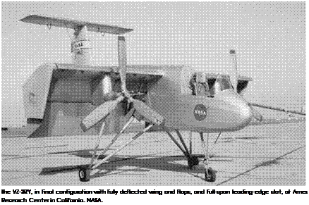
At the beginning of 1958, the Ryan Company of San Diego unveiled its Model 92, the VZ-3RY Vertiplane. The Vertiplane, a single-seat twin – propeller high wing design with a T-tail, used propeller thrust to attain vertical flight and maintain hover, deflecting the propeller slipstream via a variable-area and variable-camber wing. The wing’s trailing edge con­sisted of large, 40-percent-chord, double-slotted flaps that transformed into a gigantic curved flow channel, with wingtip ventral fins serving to further entrap the air and concentrate its flow vertically below the craft. Roll control in hover came via varying the propeller pitch to achieve changes in slipstream flow. Power to its twin three-bladed propellers was furnished by a single Lycoming T53 turboshaft engine, which also had its exhaust channeled through a tailpipe to a universal-joint noz­zle that furnished pitch and yaw control for the airplane when it was in hover mode via deflected jet thrust.[1382]

Before the aircraft flew, Ames researchers undertook a series of wind tunnel tests in the 40-foot by 80-foot full-scale wind tunnel to define performance, stability and control, and handling and control characteristics.[1383] As a result of these tests, the aircraft’s landing gear was changed from a "tail-dragger” to tricycle arrangement, and engi­neers added a ventral fin to enhance directional stability in conventional flight. Thus modified, the VZ-3RY completed its first flight January 21, 1959, piloted by Ryan test pilot Pete Girard. Less than a month later, it
Подпись: The VZ-3RY, in final configuration with fully deflected wing and flaps, and full-span leading-edge slat, at Ames Research Center in California. NASA. Подпись: 14

was damaged in a landing accident at the conclusion of its 13th flight, when a propeller pitch control mechanism malfunctioned, leaving the VZ-3RY with insufficient lift to drag (L/D) available to flare for landing. It was late summer before it returned to the air, being delivered to Ames in 1960 for NASA testing. Howard L. Turner oversaw the project, and Glen Stinnett and Fred Drinkwater undertook most of the flying. The aircraft was severely damaged when Stinnett ran out of nose-down con­trol at a low-power setting and the aircraft pitched inverted. Fortunately, Stinnett ejected before it nosed into the salt ponds north of the Moffett Field runway. Despite this seemingly disastrous accident, the aircraft was rebuilt yet again and completed the test program. The addition of full-span wing leading-edge slats to enhance lift production permitted hover out of ground effect (OGE). However, air recirculation effects lim­ited in ground effect (IGE) operation to speeds greater than 10 knots, as marginal turning of the slipstream and random upset disturbances caused by slipstream recirculation prevented true VTOL performance. A static pitch instability was often encountered at high lift coefficients, and large pitch trim changes occurred with flap deflection and power changes. The transition required careful piloting technique to avoid pitch – up. Although adequate, descent performance was limited in the extreme by low roll control power and airflow separation on the wing when power was reduced to descend. Despite these quirks and two accidents,

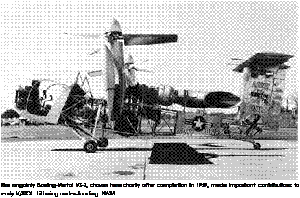
Подпись: 14the VZ-3RY demonstrated excellent STOL performance, achieving a max­imum lift coefficient of 10, with a moderate to good cruise speed range. Thus, it must be considered a successful research program. Transitions were completed from maximum speed down to 20 knots with "negligible change in longitudinal trim and at rates comparable to those done with a helicopter.”[1384] Indeed, as Turner and Drinkwater concluded in 1963, "Flight tests with the Ryan VZ-3RY V/STOL deflected-slipstream test vehicle have indicated that the concept has some outstanding advantages as a STOL aircraft where very short take-off and landing characteristics are desired.”[1385] As well as pursuing the BLC and deflected slipstream projects, NASA researchers examined tilt wing concepts then being pursued in America and abroad. The tilt wing promised a good blend of moderate low – and high-speed compatibility, with good STOL performance provided by slipstream-induced lift. For takeoff and landing, the wing would pivot so that the engine nacelles and propellers pointed vertically. After take­off, the wing would be gradually rotated back to the horizontal, enabling conventional flight. Various research aircraft were built to investigate the tilt wing approach to V/STOL flight, notably including the Canadair CL-84, Hiller X-18, the Kaman K-16B, and the joint-service Ling-Temco – Vought XC-142. The first such American aircraft was the Boeing-Vertol VZ-2 (the Vertol Model 76). It was powered by a single Lycoming YT53L1 gas turbine, driving two propellers via extension shafts and small tail fans for low-speed pitch and yaw control. Conceived from a jointly funded U. S. Army-Office of Naval Research study, the VZ-2 first flew in August 1957 and was an important early step in demonstrating the potential of tilt wing V/STOL technology. On July 16, 1958, piloted by Leonard La Vassar, it made the world’s first full-conversion of a tilt wing aircraft from vertical to horizontal flight, an important milestone in the history of V/STOL. Vertol completed its testing in September 1959 and then shipped the VZ-2 to Langley Research Center for evaluation by NASA.[1386]
Подпись: The ungainly Boeing-Vertol VZ-2, shown here shortly after completion in 1957, made important contributions to early V/STOL tilt wing understanding. NASA. Подпись: 14

Subsequent Langley tests confirmed that the tilt wing was undoubt­edly promising. However, like many first-generation technological sys­tems, the VZ-2 had a number of limitations. NASA test pilot Don Mallick recalled, "it was extremely difficult to fly,” with "lots of cross-coupling between the roll and yaw controls,” and that "It took everything I had to keep from ‘dinging’ or crashing the aircraft.”[1387] Langley research pilot Jack Reeder found that its VTOL roll control—which, as in a helicop­ter, was provided by varying the propeller pitch and hence its thrust— was too sensitive. Further, the two ducted fans at the tail responsible for pitch and yaw control furnished only marginal control power. In par­ticular, weak yaw control generated random heading deviations. When slowing into ground effect at a wing tilt angle of 70 degrees, directional instabilities were encountered, though there was no appreciable aerody­namic lift change.[1388]

Reflected flows from the ground caused buffeting and unsteady aircraft behavior, resulting in poor hover precision. Because of low
pitch control power, lack of a Stability Augmentation System (SAS), and low inherent damping of any pitch oscillations, researchers pru­dently undertook hover trials only in calm air. Among its positive qual­ities, good STOL performance was provided by slipstream-induced lift. Transition to wing-supported flight was satisfactory, with little pitch – trim change required. In transitions, as the wing pivoted down to normal flight position, hover controls were phased out. The normal aerody­namic controls were phased in, with the change from propeller to wing – supported flight being judged satisfactory. However, deceleration on descent was severely restricted by wing stall. When power was reduced, lateral – directional damping decreased to unsatisfactory levels. Changes were made to "droop” the leading edge 6 degrees to improve descent perfor­mance, and the modification improved behavior and controllability so greatly that Langley test pilot Jack Reeder concluded the "serious stall lim­itations in descent and level-flight deceleration were essentially eliminated from the range of practical flight operation, at least at incidence angles up to 50°.”[1389] In spite of this seemingly poor "report card,” the awkward – looking VZ-2 contributed greatly to early understanding of the behavior and foibles of V/STOL tilt wing designs. All together, it completed 450 research sorties, including 34 full transitions from vertical to horizontal flight. The VZ-2 flight program proved to be one of the more productive American V/STOL programs, furnishing much information on wing- propeller aerodynamic interactions and basic V/STOL handling qualities.[1390]

Подпись: 14In addition to the pioneering VZ-2, the Hiller and Kaman compa­nies also pursued the concept, the former for the Air Force and the latter for the Navy, though with significantly less success. Using an off – the-shelf development approach followed by many V/STOL programs, Hiller joined the fuselage and tail section of a Chase YC-122 assault trans­port to a tilt wing, creating the X-18, the first transport-sized tilt wing testbed. It used two Allison T40 turboprop engines driving three-bladed contra-rotating propellers, plus a Westinghouse J34 to furnish pitch control via a lengthy tailpipe. The sole X-18 made a conventional flight in November 1959 and completed a further 19 test sorties before being

grounded. Though it demonstrated wing tilt in flight to an angle of 33 degrees, it never completed a VTOL takeoff and transition. On November 4, 1960, a propeller malfunction led to it entering an inverted spin. Through superb airmanship, test pilots George Bright and Bruce Jones recovered the aircraft and landed safely, but it never flew again.[1391] Kaman undertook a similar development program for the Navy, joining a tilt wing with two General Electric T58-GE-2A turboshaft engines to the fuselage and tail section of a Grumman JRF Goose amphibian, creating the K-16B. Tested in Ames’s 40-foot by 80-foot tunnel, the K-16B never took to the air.[1392]

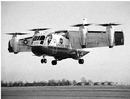
Подпись: 14Despite these failures, confidence in the tilt wing concept had advanced so rapidly that in February 1961, after 2 years of feasibility studies, the Department of Defense issued a joint-service development specification for an experimental VTOL transport that could possibly be developed into an operational military system. After evaluating pro­posals, the department selected the Vought-Hiller-Ryan Model VHR 447, ordering it into development under the Tri-Service Assault Transport Program as the XC-142A.[1393] All three of these companies had previously employed variable position wings, with the F-8 Crusader fighter, the X-18, and the VZ-3RY, though only the last two were V/STOL designs. The XC-142A was powered by four General Electric T64 turboshaft engines, each rated at 3,080 horsepower, driving four-bladed Hamilton Standard propellers, with the propellers cross-linked by drive shafts to prevent a possibly disastrous loss of control during VTOL transitions. The combi­nation of great power and light weight ensured not only that it could take off and land vertically, but also that it would have a high top-end speed of over 400 mph. Piloted by Stuart Madison, the first of five XC-142As completed a conventional takeoff in late September 1964, made its first hover at the end of December 1964, and accomplished its first transition from vertical to horizontal flight January 11, l965, "with no surprises.”[1394]

The five XC-142A test aircraft underwent extensive joint – service evaluation, moving a variety of vehicles and troops, undertaking

Подпись: 14 NACA-NASA Research on Deflected Slipstream and Tilt Wing V/STOL

simulated recovery of downed aircrew via a recovery sling, landing aboard an aircraft carrier, and even flying a demonstration at the 1967 Paris Air Show. With a payload of 8,000 pounds and a gross weight of 37,500 pounds, the XC-142A had a thrust-to-weight ratio of 1.05 to 1. In STOL mode, with the wing set at 35 degrees and with flaps set at 30 degrees, the XC-142A could almost double this payload yet still clear a 50-foot obstacle after a 200-foot takeoff run.[1395] Unfortunately, program costs rose from an estimated $66 million at inception to $115 million (in FY 1963 dollars), resulting in overruns that eventually truncated the aircraft’s development.[1396] The five aircraft experienced a number of mishaps, most related to shafting and propulsion problems. Sadly, one accident resulted in the death of test pilot Madison and a Ling-Temco-

Vought (LTV) test crew in May 1967, after a loss of tail rotor pitch con­trol from fatigue failure of a critical part during a hover at low altitude.[1397]

Подпись: 14NASA Langley took ownership of the fourth XC-142A in October 1968, subsequently flying it until May 1970. The lead pilot was Bob Champine. When these tests concluded, the program came to an end. The Air Force Scientific Advisory Board’s Aerospace Vehicle Panel concluded that, "The original premise that the propeller-tilt wing was well within the state of the art and that it was possible to go directly to operational prototypes was essentially a correct one,” and that the tilt wing "has remarkable STOL capabilities that should be exploited to the maximum.” Indeed, "One of the major advantages of the propeller – tilt wing is the fact that it is a magnificent STOL,” but the panel also acknowledged that, on the XC-142A program, "The technical surprises were few, but important.”[1398]

The results of combined contractor, military, and NASA testing indi­cated that, as Seth Anderson noted subsequently, despite the XC-142A’s clear promise:

Some mechanical control characteristics were unsatisfactory:

(1) directional friction and breakout forces varied with wing tilt angle,

(2) non-linear control gearing,

(3) possibility of control surface hard-over, and

(4) collective control had to be disengaged manually from the throttles in transition.

Hover handling qualities were good with SAS on, with no adverse flow upsets, resulting in precise spot positioning. Propeller thrust in hover was 12% less than predicted. No adverse lateral-directional char­acteristics were noted in sideward flight up to 25 knots. In slow forward flight, a long-period (20 sec) oscillation was apparent which could lead to an uncontrollable pitch-up. On one occasion full forward stick did not arrest the pitch-up, whereupon the pilot reduced engine power, the nose fell through, and the aircraft was extensively damaged in a hard landing because the pilot did not add sufficient power to arrest the high sink rate for fear of starting another pitch-up.

STOL performance was not as good as predicted and controllability compromised IGE by several factors:

(1) severe recirculation of the slipstream for wing tilt angles in the range 40° to 80° (speed range 30 to 60 knots) producing large amplitude lateral-directional upsets;

(2) weak positive, neutral, and negative static longitudinal stability; and

(3) low directional control power.

Transition corridor was satisfactory with ample acceleration and deceleration capabilities. Conventional flight performance was less than predicted (11% less) due to large boat-tail drag-cruise.

Подпись: 14Stability and control was deficient in several areas:

(1) low to neutral pitch stability,

(2) nonlinear stick force per "g” gradient, and

(3) tendency for a pitch Pilot Induced Oscillation (PIO) during recovery from rolling maneuvers.[1399]

A failure of the drive shaft to the tail pitch propeller in low-speed flight caused a fatal crash that essentially curtailed further development of this concept. The experience of Canadair with the CL-84 Dynavert, a twin-engine tilt wing powered by two Lycoming T53 turboshafts, was in many respects similar to that of the XC-142A. In October 1966, NASA Langley pilots Jack Reeder and Bob Champine had evaluated the CL-84 at the manufacturer’s plant, finding that, "The flying qualities were considered generally good except for a slow arrest of rate of descent at constant power and airspeed that could be of particular significance dur­ing instrument flight.”[1400] For a while after the conclusion of the XC-142A
program, the U. S. Navy sponsored further tilt rotor research with the Canadair CL-84, in trials at sea and at the Naval Air Test Center, Patuxent River, MD, looking at combat search and rescue and fleet logistical sup­port missions. Undoubtedly, it was a creative design of great promise and clear potential, marred by a series of mishaps, though fortunately without loss of life. But after 1974, when the CL-84 joined the XC-142 in retirement, whatever merits the tilt wing might have possessed for piloted aircraft were set aside in favor of other technical approaches.

The Experiments

The HSR Program Office assigned the six Phase I and one Phase II flight experiments reference numbers.

All six Phase I experiments were continued in Phase II and were iden­tified in their Phase II form by the letter "A” following the number. Only experiment 1.5 changed in nature in Phase II. All of the experiments
were assigned Tupolev principal investigator counterparts. The experiments and principal NASA-Boeing investigators are listed below:

• 1.2 Surface/Structure Equilibrium Temperature Verification: Craig Stephens (NASA Dryden).

• 1.5 Propulsion System Thermal Environment: Warren Beaulieu (Boeing).

• 1.5A Fuel System Thermal Database: Warren Beaulieu (Boeing).

• 1.6 Slender Wing Ground Effects: Robert Curry (NASA Dryden).

• 2.1 Structure/Cabin Noise: Stephen Rizzi (NASA Langley) and Robert Rackl (Boeing).

Подпись: 152.4 Handling Qualities Assessment: Norman Princen (Boeing).

• 3.3 Cp, Cf, and Boundary Layer Measurement and CFD Comparisons: Paul Vijgen (Boeing).

• 4.1 In-Flight Wing Deflection Measurements: Robert Watzlavick (Boeing).[1486]

Because the HSR program was the primary funding source for the Tu-144LL flight experiment, it followed that the relevant HSR Integrated Technology Development (ITD) teams would be the primary customers. Subsequent to Phase I, however, it became apparent that some of the exper­iments did not have the ITD teams’ complete support. The experimenters believed that data analysis would be accomplished by the interested ITD teams, but the ITD teams who had little or no input in the planning and selection of the experiments had no plans to use the data. This was com­plicated by the cancellation of the HSR program by NASA in April 1999.[1487] In retrospect, it appeared that the experiment selection process did not properly consider the ultimate needs of the logical customers in all cases. In deference to the HSR program, however, it should be noted that the joint U. S.-Russian Tu-144 project had political aspects that had to be considered and inputs for data from Tupolev that may not have fit neatly into HSR requirements. Fortunately, the bulk of the raw data from all of

the experiments, except Langley’s 2.1 and 2.1A, is maintained at NASA Dryden.[1488] The data from 2.1 were fully analyzed and reported in several NASA and Boeing reports.[1489]

Подпись: 15The data from all but experiment 2.1, Structure/Cabin Noise, were collected by the Damien DAS and were for the most part managed in Zhukovsky by Tupolev engineers. Experiment 2.1 had a dedicated DAS and experienced none of the data acquisition problems suffered at times by the other experiments. NASA Dryden’s Glenn A. Bever was the NASA onsite engineer and instrumentation engineer for the dura­tion of the program. In this capacity, he supported all of the experi­ments, except Langley’s experiment 2.1, which had its own engineers and technicians. From 1995 to 1999, Bever made 19 trips to Zhukovsky, "a total of 8 months in Russia all told hitting every month of the year at least once.”[1490] Because Dryden had responsibility for instrumentation, Bever worked with Tupolev instrumentation engineers and technicians directly to ensure that all of the experiments’ data other than 2.1 were properly captured. Often, he was the only American in Zhukovsky and found himself the point of contact for all aspects of the project. He "wrote Summaries of Discussion at the end of each trip which tended, we discovered, to act like contracts to direct what work was to happen next and document deliverables and actions.”[1491] Bever utilized a rather new concept at the time, when he transmitted all of the collected data from the experiments under his purview to Dryden via the Internet. He translated the instrumentation calibration information files into English calibration files, wrote the programs that reduced the data to a manip­ulative format, applied the calibrations, formatted the data for storage, and archived the data on Dryden’s flight data computer and on CDs. One of his final accomplishments was to design the air data sensor sys­tem that collected altitude and airspeed information from the Phase II flights flown by the NASA pilots.[1492] Langley’s instrumentation technician,

Donna Amole, and Dryden’s Project Manager, Russ Barber, attested to the significant efforts Bever contributed to the project.

Подпись: 15Experiment 1.2/1.2A, Surface/Structure Equilibrium Temperature, consisted of 250 thermocouples and 18 heat flux gauges installed on pre­determined locations on the left wing, fuselage, and engine nacelles, which measured temperatures from takeoff through landing on Mach 1.6 and 2 test flights.[1493] High noise levels and significant zero offsets resulted in poor quality data for the Phase I flights. This was due to problems with the French-built Damien DAS. For Phase II, a Russian-designed Gamma DAS was used, with higher-quality data being recorded. Unfortunately, the HSR program did not analyze the data, because the relevant ITD team did not believe this experiment was justified, based on prior work and preexisting prediction capability at these Mach numbers. The initial poor data quality also did not suggest that further analysis was warranted.[1494]

Experiment 1.5, Propulsion System Thermal Environment, sampled temperatures in the engine compartment and inlet and measured acces­sory section maximum temperatures, engine compartment cooling airflow, and engine temperatures after shutdown. Thirty-two thermocouples on the engine, 35 on the firewall, and 10 on the outboard shield recorded the temperature data.[1495] The data provided valuable information on thermal lag during deceleration from Mach 2 flight and on the temperature profiles in the engine compartment after shutdown. Experiment 1.5A in Phase II developed a Thermal Database on the aircraft fuel system using 42 resis­tance temperature devices and 4 fuel flow meters to collect temperature and fuel flow time histories on engines 1 and 2 and heat rejection data on the engine oil system during deceleration from supersonic speeds. HSR engineers did not fully analyze these data before program cancellation.[1496]

Experiments 1.6/1.6A, Slender Wing Ground Effects, demonstrated no evidence of dynamic ground effects on the Tu-144LL. This correlated
with wind tunnel data and NASA evaluation pilot comments.[1497] Effects were determined on lift, drag, and pitching moment with the canard, both retracted and extended. Forty-eight parameters were measured in flight, including inertial parameters, control surface positions, height above the ground, airspeed, and angle of attack. From these, aerodynamic forces and moments were derived, and weight and thrust were computed postflight. A NASA Differential Global Positioning System (DGPS) provided highly pre­cise airspeed and angle-of-attack data and repeatable heights above run­way accurate to less than 0.5 feet. Getting this essential DGPS equipment into Russia had been difficult because of Russian import restrictions. In Phase I, 10 good maneuvers from the 19 flights were accomplished, eval­uating a range of weights, sink rates, and canard positions. The data qual­ity was excellent, and the results indicated that there is still much to be learned regarding dynamic ground effects for slender, swept wing aircraft.[1498]

Подпись: 15Langley’s Structure/Cabin Noise, experiment 2.1, was unique among the seven flight experiments, in that it used its own Langley-built DAS and had on site its own support personnel for all flights on which data were collected. Another unique feature of this experiment was its direct tie to a specific customer, the HSR structural acoustics ITD team. The two principal investigators, Stephen Rizzi and Robert Rackl, were members of the team, and Rizzi was the team lead. This arrangement allowed the structure of the experiment to be designed directly to meet team require­ments.[1499] Several datasets, including boundary layer fluctuating pressure measurements, fuselage sidewall vibration and interior noise data, jet noise data, and inlet noise data, were used to update or validate various acoustic models, such as a boundary layer noise source model, a cou­pled boundary layer/structural interaction model, a near-field jet noise model, and an inlet noise model.[1500] The size of the dataset and sampling rates was staggering. The required rate was 40,000 samples per second for each of 32 channels. The Damien DAS was not capable of sampling at these rates, thus necessitating the Langley DAS. Langley, as a result, provided personnel on site to support experiment 2.1. These included

Rizzi, Rackl, and several instrumentation technicians from Langley’s Flight Instrumentation Branch, including Vernie Knight, Keith Harris, and Donna Amole, the only onsite American female on the project. Amole spent about 5 months in Zhukovsky during 8 trips. Her first trip was chal­lenging, to say the least. The Tupolev personnel were not eager to have an American woman working with them. Whether because of supersti­tion (Amole initially was told she could not enter the airplane on flight days), cultural differences, or perhaps a misunderstood fear of poten­tial American sexual harassment issues, Amole for the first 2 weeks was essentially ignored by her Tupolev counterparts. She would not be deterred, however, and won the respect and friendship of her Russian colleagues. Glenn Bever and Stephen Rizzi provided essential support, but many times, she was, like Bever, the only American on site.[1501]

Подпись: 15Experiment 2.4, Handling Qualities Assessment, suffered in Phase I from poor data quality, which predicted a very poor flying aircraft. The aircraft response to control deflections indicated a 0.25-second delay between control movement and aircraft response. Furthermore, angle-of – attack, angle-of-sideslip, heading, altitude, and airspeed data all were of suspect quality at times.[1502] These data issues contributed to the HSR pro­gram’s desire for U. S. pilots to fly the airplane to evaluate the handling qualities, because access to the Tupolev pilots was limited. Additionally, in Phase II, a new air data sensor from NASA Dryden corrected the nag­ging air data errors. This experiment will be covered in more detail in the following section on the Tu-144LL Handling Qualities Assessment.

Experiments 3.3/3.3A—Cp, Cf, and Boundary Layer Measurements— collected data on surface pressures, local skin friction coefficients, and boundary layer profiles on the wing and fuselage using 76 static pressure orifices, 16 skin friction gauges consisting of 10 electromechanical bal­ances and 6 hot film sensors, 3 boundary layer rakes, 3 reference probes, 5 full chord external pressure belts consisting of 3 on the wing upper sur­face and 2 on the lower surface, and angle-of-attack and angle-of-sideslip vanes. Measurements from the 250 thermocouples from experiment 1.2 were used in the aerodynamic data analysis.[1503] Data were collected at Mach

0. 9, 1.6, and 2 and included over 80 minutes of stabilized supersonic flight. Data quality was good, although some calibration problems with the pressure transducers and mechanical skin friction balances arose. On flight 10, the lower wing surface midspan pressure belt detached and was lost, and 4 tubes on the upper midspan belt debonded. Fortunately, the failures occurred after the minimum data requirements had been met. In Phase II, Preston tubes and optical-mechanical sensors devel­oped at Russia’s Central Institute of Aerohydromechanics (TsAGI) were implemented for additional skin friction measurements. The HSR pro­gram did not fully analyze these data, believing that prior XB-70 data already filled these requirements.[1504]

Подпись: 15Experiment 4.1A, In-Flight Wing Deflection Measurements, pro­vided a limited verification of the wing geometry under in-flight loads. These data are needed for validating the aeroelastic prediction meth­odology and providing the in-flight geometry needed in computational fluid dynamics analysis. Boeing’s Optitrak active target photogrammetry system was used, and Boeing managed the experiment. The installed system incorporated 24 infrared reflectors mounted on the upper sur­face of the right wing, each pulsed in sequence. Two cameras captured the reflected signals in order to provide precise x, y, and z coordinates.[1505] The system was used on Langley’s Boeing 737 in the early 1990s high lift experiment, designed to quantify the precise effect of high-lift devices.

Not listed among the formal experiments was a Phase II indepen­dent "piggyback” experiment leveraging off the data collected from experiment 2.4, Handling Qualities Assessment, flown by the NASA research pilots. This involved a new longitudinal, lateral, and direc­tional closed-loop Low-Order Equivalent System (LOES) method of air­craft parameter identification using an equation-error method in the frequency domain. Because the data were accumulated by pilot-in-the – loop frequency sweep and multistep maneuvers, these were added to the test cards for the first four Phase II flights.[1506] Langley’s Dr. Eugene A. Morrelli requested theses datasets and developed the pilot maneuvers necessary to acquire them. This was a unique example of a researcher taking advantage of his colleagues’ work on a once-in-a-lifetime
experiment and of the spirit of cooperation among NASA researchers that allowed this opportunity develop.

Partners in the Sky: 1965

The partnership between NASA and the FAA that facilitates that exchange of ideas and technology was forged soon after both agencies were for­mally created in 1958. With the growing acceptance of commercial jet air­liners and the ever-increasing number of passengers who wanted to get to their destinations as quickly as possible, the United States began explor­ing the possibility of fielding a Supersonic Transport (SST). By 1964, it was suggested that duplication of effort was underway by researchers at the FAA and NASA, especially in upgrading existing jet powerplants required to propel the speedy airliner. The resulting series of meetings during the next year led to the creation in May 1965 of the NASA-FAA Coordinating Board, which was designed to "strengthen the coordina­tion, planning, and exchange of information between the two agencies.”[187]

Airspace Concept Evaluation System

The Airspace Concept Evaluation System (ACES) is a computer tool that allows researchers to try out novel Air Traffic Management (ATM) the­ories, weed out those that are not viable, and identify the most promis­ing concepts. ACES looks at how a proposed air transportation concept can work within the National Airspace System (NAS), with the aim of reducing delays, increasing capacity, and handling projected growth in air traffic. ACES does this by simulating the major components of the NAS, modeling a flight from gate to gate, and taking into account in its models the individual behaviors of those that affect the NAS, from depar­ture clearance to the traffic control tower, the weather office, navigation systems, pilot experience, type of aircraft, and other major components. ACES also is able to predict how one individual behavior can set up a ripple effect that touches, or has the potential to touch, the entire NAS. This modeling approach isolates the individual models so that they can continue to be enhanced, improved, and modified to represent new con­cepts without impacting development of the overall simulation system.[251]

Among the variables ACES has been tasked to run through its sim­ulations are environmental impacts when a change is introduced,[252] use

of various communication and navigation models,[253] validation of cer­tain concepts under different weather scenarios,[254] adjustments to spac­ing and merging of traffic around dense airports,[255] and reduction of air traffic controller workload by automating certain tasks.[256]