Category NASA’S CONTRIBUTIONS TO AERONAUTICS

Into the 21st Century

Подпись: 10In 2004, NASA Headquarters Aeronautics Research Mission Directorate (ARMD) formed the Vehicle Systems Program (VSP) to preserve core supersonic research capabilities within the Agency.[1118] As the program had limited funding, much of the effort concentrated on cooperation with other organizations, notably the Defense Advanced Research Projects Agency (DARPA) and the military. Likely configuration studies pointed toward business jets as being a more likely candidate for supersonic trav­elers than full-size airliners. More effort was devoted to cooperation with DARPA on the sonic boom problem. An earlier joint program resulted in the shaped sonic boom demonstration of 2003, when a Northrop F-5 fighter with a forward fuselage modified to reduce the type’s characteris­tic sonic boom signature demonstrated that the modification worked.[1119]

Подпись: Among the supersonic cruise flight-test research tools, circa 2007, was thermal imagery. NASA.

Military aircraft have traversed the sonic regime so frequently that one can hardly dignify it with the name "frontier” that it once had.

10

Into the 21st Century

Into the 21st Century

In-flight Schlieren imagery. NASA.


10


Подпись: RTDs (К)

Into the 21st Century

In-flight thermography output. NASA.

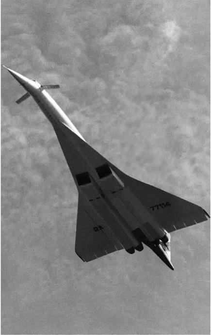
Подпись: 10Nevertheless, there have been few supercruising aircraft: the SR-71, the Concorde, the Tu-144, and the F-22A constituting notable exceptions. The operational experience gained with the SR-71 fleet with its DAFICS in the 1980s, and the more recent Air Force experience with the low – observable supercruising Lockheed-Martin F-22A Raptor, indicate that a properly designed aircraft with modern digital systems makes high Mach supersonic cruise now within reach technologically. Indeed, at a November 2007 Langley Research Center presentation at the annual meeting of the Aeronautics Research Mission Directorate reflected that although no supersonic cruise aircraft is lying, digital simulation capa­bilities, advanced test instrumentation, and research tools developed in support of previous programs are nontrivial legacies of the supersonic cruise study programs, positioning NASA well for any nationally iden­tified supersonic cruise aircraft requirement. Whether that will occur in the near future remains to be seen, just as it has since the creation of NASA a half century ago, but one thing is clear: the more than three decades of imaginative NASA supersonic cruise research after cancel­lation of the SST have produced a technical competency permitting, if needed, design for routine operation of a high Mach supersonic cruiser.[1120]

Into the 21st Century

NASA synthetic vision research promises to increase flight safety by giving pilots perfect posi­tional and situation awareness, regardless of weather or visibility conditions. Richard P. Hallion.


Learning to Fly with SLDs

From the earliest days of aviation, the easiest way for pilots to avoid problems related to weather and icing was to simply not fly through clouds or in conditions that were less than ideal. This made weather forecasting and the ability to quickly and easily communicate observed conditions around the Nation a top priority of aviation researchers. Working with the National Oceanic and Atmospheric Administration (NOAA) during the 1960s, NASA orbited the first weather satellites, which began equipped with black-and-white television cameras and

Подпись: 12 Подпись: Post-flight image shows ice contamination on the NASA Twin Otter airplane as a result of encountering Supercooled Large Droplet (SLD) conditions near Parkersburg, WV.

have since progressed to include sensors capable of seeing beyond the range of human eyesight, as well as lasers capable of characterizing the contents of the atmosphere in ways never before possible.[1248]

Our understanding of weather and the icing phenomenon, in com­bination with the latest navigation capabilities—robust airframe man­ufacturing, anti – and de-icing systems, along with years of piloting experience—has made it possible to certify airliners to safely fly through almost any type of weather where icing is possible (size of the freezing rain is generally between 100 and 400 microns). The exception is for one category in which the presence of supercooled large drops (SLDs) are detected or suspected of being there. Such rain is made up of water droplets that are greater than 500 microns and remain in a liquid state even though its temperature is below freezing. This makes the drop very unstable, so it will quickly freeze when it comes into contact with a cold object such as the leading edge of an airplane. And while some
of the SLDs do freeze on the wing’s leading edge, some remain liquid long enough to run back and freeze on the wing surfaces, making it dif­ficult, if not impossible, for de-icing systems to properly do their job. As a result, the amount of ice on the wing can build up so quickly, and so densely, that a pilot can almost immediately be put into an emergency situation, particularly if the ice so changes the airflow over the wing that the behavior of the aircraft is adversely affected.

Подпись: 12This was the case on October 31, 1994 when American Eagle Flight 4184, a French-built ATR 72-212 twin-turboprop regional airliner car­rying a crew of 4 and 64 passengers, abruptly rolled out of control and crashed in Roselawn, IN. During the flight, the crew was asked to hold in a circling pattern before approaching to land. Icing conditions existed, with other aircraft reporting rime ice buildup. Suddenly the ATR 72 began an uncommanded roll; its two pilots heroically attempted to recover as the plane repeatedly rolled and pitched, all the while diving at high speed. Finally, as they made every effort to recover, the plane broke up at a very low altitude, the wreckage plunging into the ground and bursting into flame. An exhaustive investigation, including NASA tests and tests of an ATR 72 flown behind a Boeing NKC-135A icing tanker at Edwards Air Force Base, revealed that the accident was all the more tragic for it had been completely preventable. Records indicated that the ATR 42 and 72 had a marked propensity for roll-control incidents, 24 of which had occurred since 1986 and 13 of which had involved icing. The National Transportation Safety Board (NTSB) report concluded:

The probable cause of this accident were the loss of control, attributed to a sudden and unexpected aileron hinge moment reversal that occurred after a ridge of ice accreted beyond the deice boots because: 1) ATR failed to completely disclose to operators, and incorporate in the ATR 72 airplane flight manual, flightcrew operating man­ual and flightcrew training programs, adequate infor­mation concerning previously known effects of freeing precipitation on the stability and control characteristics, autopilot and related operational procedures when the ATR 72 was operated in such conditions; 2) the French Directorate General for Civil Aviation’s (DGAC’s) inade­quate oversight of the ATR 42 and 72, and its failure to take the necessary corrective action to ensure continued
airworthiness in icing conditions; and 3) the DGAC’s failure to provide the FAA with timely airworthiness information developed from previous ATR incidents and accidents in icing conditions, as specified under the Bilateral Airworthiness Agreement and Annex 8 of the International Civil Aviation Organization.

Подпись: 12Contributing to the accident were; 1) the Federal Aviation Administration’s (FAAs) failure to ensure that air­craft icing certification requirements, operational require­ments for flight into icing conditions, and FAA published aircraft icing information adequately accounted for the hazards that can result from light in freezing rain and other icing conditions not specified in 14 Code of Federal Regulations 9CFR) part 25, Appendix C; and 2) the FAA’s inadequate oversight of the ATR 42 and 72 to ensure con­tinued airworthiness in icing conditions. [1249]

This accident focused attention on the safety hazard associated with SLD and prompted the FAA to seek a better understanding of the atmo­spheric characteristics of the SLD icing condition in anticipation of a rule change regarding certifying aircraft for flight through SLD condi­tions, or at least long enough to safely depart the hazardous zone once SLD conditions were encountered. Normally a manufacturer would demonstrate its aircraft’s worthiness for certification by flying in actual SLD conditions, backed up by tests involving a wind tunnel and com­puter simulations. But in this case such flight tests would be expensive to mount, requiring an even greater reliance on ground tests. The trou­ble in 1994 was lack of detailed understanding of SLD precipitation that could be used to recreate the phenomenon in the wind tunnel or pro­gram computer models to run accurate simulations. So a variety of flight tests and ground-based research was planned to support the decision­making process on the new certification standards.[1250]

Подпись: 12

Подпись: NASA's Twin Otter ice research aircraft, based at the Glenn Research Center in Cleveland, is shown in flight.

One interesting approach NASA took in conducting basic research on the behavior of SLD rain was to employ high-speed, close-up photography. Researchers wanted to learn more about the way an SLD strikes an object: is it more of a direct impact, and/or to what extent does the drop make a splash? Investigators also had similar questions about the way ice particles impacted or bounced when used during research in an icing wind tunnel such as the one at GRC. With water droplets less than 1 millimeter in diameter and the entire impact process taking less than 1 second in time, the close-up, high-speed imaging technique was the only way to capture the sought-after data. Based on the results from these tests, follow-on tests were conducted to investigate what effect ice particle impacts might have on the sensing elements of water content measurement devices.[1251]

Another program to understand the characteristics of SLDs Supercooled Large Droplets involved a series of flight tests over the Great Lakes during the winter of 1996-1997. GRC’s Twin Otter icing research aircraft was flown in a joint effort with the FAA and the National Center for Atmospheric Research (NCAR). Based on weather forecasts
and real-time pilot reports of in-flight icing coordinated by the NCAR, the Twin Otter was rushed to locations where SLD conditions were likely. Once on station, onboard instrumentation measured the local weather conditions, recorded any ice accretion that took place, and registered the aerodynamic performance of the aircraft in response to the icing. A total of 29 such icing research sorties were conducted, exposing the flight research team to all the sky has to offer—from normal-sized pre­cipitation and icing to SLD conditions, as well as mixed phase condi­tions. Results of the flight tests added to the database of knowledge about SLDs and accomplished four technical objectives that included charac­terization of the SLD environment aloft in terms of droplet size distri­bution, liquid water content, and measuring associated variables within the clouds containing SLDs; development of improved SLD diagnostic and weather forecasting tools; increasing the fidelity of icing simula­tions using wind tunnels and icing prediction software (LEWICE); and providing new information about SLD to share with pilots and the fly­ing community through educational outreach efforts.[1252]

Подпись: 12Thanks in large measure to the SLD research done by NASA in part­nership with other agencies—an effort NASA Associate Administrator Jaiwon Shin ranks as one of the top three most important contribu­tions to learning about icing—the FAA is developing a proposed rule to address SLD icing, which is outside the safety envelope of current icing certification requirements. According to a February 2009 FAA fact sheet: "The proposed rule would improve safety by taking into account super­cooled large-drop icing conditions for transport category airplanes most affected by these icing conditions, mixed-phase and ice-crystal condi­tions for all transport category airplanes, and supercooled large drop, mixed phase, and ice-crystal icing conditions for all turbine engines.”[1253]

As of September 2009, SLD certification requirements were still in the regulatory development process, with hope that an initial, draft rule would be released for comment in 2010.[1254]

Precision Controllability Flight Studies

During the 1970s, NASA Dryden conducted a series of flight assessments of emerging fighter aircraft to determine factors affecting the precision
tracking capability of modern fighters at transonic conditions.[1301] Although the flight evaluations did not explore the flight envelope beyond stall and departure, they included strenuous maneuvers at high angles of attack and explored typical such handling quality deficiencies as wing rock (undesirable large-amplitude rolling motions), wing drop, and pitch – up encountered during high-angle-of-attack tracking. Techniques were developed for the assessment process and were applied to seven differ­ent aircraft during the study. Aircraft flown included a preproduction version of the F-15, the YF-16 and YF-17 Lightweight Fighter proto­types, the F-111A and the F-111 supercritical wing research aircraft, the F-104, and the F-8.

Подпись: 13Extensive data were acquired in the flight-test program regarding the characteristics of the specific aircraft at transonic speeds and the impact of configuration features such as wing maneuver flaps and auto­matic flap deflection schedules with angle of attack and Mach number. However, some of the more valuable observations relative to undesirable and uncommanded aircraft motions provided insight and guidance to the high-angle-of-attack research community regarding aerodynamic and control system deficiencies and the need for research efforts to mitigate such issues. In addition, researchers at Dryden significantly expanded their experience and expertise in conducting high-angle-of-attack flight evaluations and developing methodology to expose inherent handling- quality deficiencies during tactical maneuvers.

Appendix: Lessons from Flight-Testing the XV-5 and X-14 Lift Fans

Note: The following compilation of lessons learned from the XV-5 and X-14 programs is excerpted from a report prepared by Ames research pilot Ronald M. Gerdes based upon his extensive flight research experience with such aircraft and is of interest because of its reference to Supersonic Short Take-Off, Vertical Landing Fighter (SSTOVLF) studies anticipat­ing the advent of the SSTOVLF version of the F-35 Joint Strike Fighter:[1457]

Подпись: 14The discussion to follow is an attempt to apply the key issues of "lessons learned” to what might be applicable to the prelim­inary design of a hypothetical Supersonic Short Take-off and Vertical Landing Fighter/attack (SSTOVLF) aircraft. The objec­tive is to incorporate pertinent sections of the "Design Criteria Summary” into a discussion of six important SSTOVLF pre­liminary design considerations to form the viewpoint of the writer’s lift-fan aircraft flight test experience. These key issues are discussed in the following order: (1) Merits of the Gas – Driven Lift-Fan, (2) Lift-Fan Limitations, (3) Fan-in-Wing Aircraft Handling Qualities, (4) Conversion System Design, (5) Terminal Area Approach Operations, and (6) Human Factors.

MERITS OF THE XV-5 GAS-DRIVEN LIFT-FAN

The XV-5 flight test experience demonstrated that a gas-driven lift-fan aircraft could be robust and easy to maintain and oper­ate. Drive shafts, gear boxes and pressure lubrication systems, which are highly vulnerable to enemy fire, were not required with gas drive. Pilot monitoring of fan machinery health is thus reduced to a minimum which is highly desirable for a single – piloted aircraft such as the SSTOVLF. Lift-fans have proven to be highly resistant to ingestion of foreign objects which is a plus for remote site operations. In one instance an XV-5A wing – fan continued to produce substantial lift despite considerable damage inflicted by the ingestion of a rescue collar weight. All pilots who have flown the XV-5 felt confident in the integrity of the lift-fans, and it was felt that the combat effectiveness of the SSTOVLF would be enhanced by using gas-driven lift-fans.

Assessing NASA’s Wind Shear Research Effort

NASA’s wind shear research effort involved complex, cooperative rela­tionships between the FAA, industry manufacturers, and several NASA Langley directorates, with significant political oversight, scrutiny, and public interest. It faced many significant technical challenges, not the least of which were potentially dangerous flight tests and evaluations.[91] Yet, during a 7-year effort, NASA, along with industry technicians and researchers, had risen to the challenge. Like many classic NACA research projects, it was tightly focused and mission-oriented, taking "a proven,
significant threat to aviation and air transportation and [developing] new technology that could defeat it.”[92] It drew on technical capabilities and expertise from across the Agency—in meteorology, flight systems, aero­nautics, engineering, and electronics—and from researchers in industry, academia, and agencies such as the National Center for Atmospheric Research. This collaborative effort spawned several important break­throughs and discoveries, particularly the derivation of the F-Factor and the invention of Langley’s forward-looking Doppler microwave radar wind shear detector. As a result of this Government-industry-academic partnership, the risk of microburst wind shear could at last be mitigated.[93]

Assessing NASA's Wind Shear Research EffortIn 1992, the NASA-FAA Airborne Windshear Research Program was nominated for the Robert J. Collier Trophy, aviation’s most prestigious honor. Industry evaluations described the project as "the perfect role for NASA in support of national needs” and "NASA at its best.” Langley’s Jeremiah Creedon said, "we might get that good again, but we can’t get any better.”[94] In any other year, the program might easily have won, but it was the NASA-FAA team’s ill luck to be competing that year with the revolutionary Global Positioning System, which had proven its value in spectacular fashion during the Gulf War of 1991. Not surprisingly, then, it was GPS, not the wind shear program, which was awarded the Collier Trophy. But if the wind shear team members lost their shot at this pres­tigious award, they could nevertheless take satisfaction in knowing that together, their agencies had developed and demonstrated a "technology base” enabling the manufacture of many subsequent wind shear detec­tion and prediction systems, to the safety and undoubted benefit of the traveling public, and airmen everywhere.[95]

NASA engineers had coordinated their research with commercial manufacturers from the start of wind shear research and detector devel­opment, so its subsequent transfer to the private sector occurred quickly and effectively. Annual conferences hosted jointly by NASA Langley and the FAA during the project’s evolution provided a ready forum for manufacturers to review new technology and for NASA researchers to obtain a better understanding of the issues that manufacturers were
encountering as they developed airborne equipment to meet FAA cer­tification requirements. The fifth and final combined manufacturers’ and technologists’ airborne wind shear conference was held at NASA Langley on September 28-30, 1993, marking an end to what NASA and the FAA jointly recognized as "the highly successful wind shear experi­ments conducted by government, academic institutions, and industry.” From this point onward, emphasis would shift to certification, regula­tion, and implementation as the technology transitioned into commer­cial service.[96] There were some minor issues among NASA, the airlines, and plane manufacturers about how to calibrate and where to place the various components of the system for maximum effectiveness. Sometimes, the airlines would begin testing installed systems before NASA finished its testing. Airline representatives said that they were pleased with the system, but they noted that their pilots were highly trained profession­als who, historically, had often avoided wind shear on their own. Pilots, who of course had direct control over plane performance, wished to have detailed information about the system’s technical components. Airline rep­resentatives debated the necessity of considering the performance spec­ifications of particular aircraft when installing the airborne system but ultimately went with a single Doppler radar system that could work with all passenger airliners.[97] Through all this, Langley researchers worked with the FAA and industry to develop certification standards for the wind shear sensors. These standards involved the wind shear hazard, the cock­pit interface, alerts given to flight crews, and sensor performance levels. NASA research, as it had in other aspects of aeronautics over the history of American civil aviation, formed the basis for these specifications.[98]

Assessing NASA's Wind Shear Research EffortAlthough its airborne sensor development effort garnered the great­est attention during the 1980s and 1990s, NASA Langley also devel­oped several ground-based wind shear detection systems. One was the

low-level wind shear alert system installed at over 100 United States air­ports. By 1994, ground-based radar systems (Terminal Doppler Weather Radar) were in place at hundreds of airports that could predict when such shears would come, but plane-based systems continue to be neces­sary because not all of the thousands of airports around the world had such systems. Of plane-based systems, NASA’s forward-looking predic­tive radar worked best.[99]

Assessing NASA's Wind Shear Research EffortThe end of the tyranny of microburst did not come without one last serious accident that had its own consequences for wind shear allevia­tion. On July 2, 1994, US Air Flight 1016, a twin-engine Douglas DC-9, crashed and burned after flying through a microburst during a missed approach at Charlotte-Douglas International Airport. The crew had real­ized too late that conditions were not favorable for landing on Runway 18R, had tried to go around, and had been caught by a violent micro­burst that sent the airplane into trees and a home. Of the 57 passen­gers and crew, 37 perished, and the rest were injured, 16 seriously. The NTSB faulted the crew for continuing its approach "into severe con­vective activity that was conducive to a microburst,” for "failure to rec­ognize a windshear situation in a timely manner,” and for "failure to establish and maintain the proper airplane attitude and thrust setting necessary to escape the windshear.” As well, it blamed a "lack of real­time adverse weather and windshear hazard information dissemination from air traffic control.”[100] Several factors came together to make the accident more tragic. In 1991, US Air had installed a Honeywell wind shear detector in the plane that could furnish the crew with both a visual warning light and an audible "wind shear, wind shear, wind shear” warn­ing once an airplane entered a wind shear. But it failed to function dur­ing this encounter. Its operating algorithms were designed to minimize "nuisance alerts,” such as routine changes in aircraft motions induced by flap movement. When Flight 1016 encountered its fatal shear, the plane’s landing flaps were in transition as the crew executed its missed approach, and this likely played a role in its failure to function. As well, Charlotte had been scheduled to be the fifth airport to receive Terminal Doppler Weather Radar, a highly sensitive and precise wind shear

detection system. But a land dispute involving the cost of property that the airport was trying to purchase for the radar site bumped it from 5 th to 38 th on the list to get the new TDWR. Thus, when the accident occurred, Charlotte only had the far less capable LLWAS in service.[101] Clearly, to survive the dangers of wind shear, airline crews needed air­craft equipped with forward-looking predictive wind shear warning systems, airports equipped with up-to-date precise wind shear Doppler radar detection systems, and air traffic controllers cognizant of the prob­lem and willing to unhesitatingly shift flights away from potential wind shear threats. Finally, pilots needed to exercise extreme prudence when operating in conditions conducive to wind shear formation.

Assessing NASA's Wind Shear Research EffortNot quite 5 months later, on November 30, 1994, Continental Airlines Flight 1637, a Boeing 737 jetliner, lifted off from Washington-Reagan Airport, Washington, DC, bound for Cleveland. It is doubtful whether any passengers realized that they were helping usher in a new chapter in the history of aviation safety. This flight marked the introduction of a commercial airliner equipped with a forward-looking sensor for detect­ing and predicting wind shear. The sensor was a Bendix RDR-4B devel­oped by Allied Signal Commercial Avionic Systems of Fort Lauderdale, FL. The RDR-4B was the first of the predictive Doppler microwave radar wind shear detection systems based upon NASA Langley’s research to gain FAA certification, achieving this milestone on September 1, 1994. It consisted of an antenna, a receiver-transmitter, and a Planned Position Indicator (PPI), which displayed the direction and distance of a wind shear microburst and the regular weather display. Since then, the num­ber of wind shear accidents has dropped precipitously, reflecting the proliferation and synergistic benefits accruing from both air – and land – based advanced wind shear sensors.[102]

In the mid-1990s, as part of NASA’s Terminal Area Productivity Program, Langley researchers used numerical modeling to predict weather in the area of airport terminals. Their large-eddy simulation (LES) model had a meteorological framework that allowed the predic­tion and depiction of the interaction of the airplane’s wake vortexes (the rotating turbulence that streams from an aircraft’s wingtips when it passes through the air) with environments containing crosswind shear,
stratification, atmospheric turbulence, and humidity. Meteorological effects can, to a large degree, determine the behavior of wake vortexes. Turbulence can gradually decay the rotation of the vortex, robbing it of strength, and other dynamic instabilities can cause the vortex to collapse. Results from the numerical simulations helped engineers to develop useful algorithms to determine the way aircraft should be spaced when aloft in the narrow approach corridors surrounding the airport terminal, in the presence of wake turbulence. The models utilized both two and three dimensions to obtain the broadest possible picture of phenomena interaction and provided a solid basis for the development of the Aircraft Vortex Spacing System (AVOSS), which safely increased airport capacity.[103]

Assessing NASA's Wind Shear Research EffortIn 1999, researchers at NASA’s Goddard Space Flight Center in Greenbelt, MD, concluded a 20-year experiment on wind-stress simulations and equatorial dynamics. The use of existing datasets and the creation of models that paired atmosphere and ocean forecasts of changes in sea surface temperatures helped the researchers to obtain predictions of climatic conditions of large areas of Earth, even months and years in advance. Researchers found that these conditions affect the speed and timing of the transition from laminar to turbulent air­flow in a plane’s boundary layer, and their work contributed to a more sophisticated understanding of aerodynamics.[104]

In 2008, researchers at NASA Goddard compared various NASA satellite datasets and global analyses from the National Centers for Environmental Protection to characterize properties of the Saharan Air Layer (SAL), a layer of dry, dusty, warm air that moves westward off the Saharan Desert of Africa and over the tropical Atlantic. The researchers also examined the effects of the SAL on hurricane development. Although the SAL causes a degree of low-level vertical wind shear that pilots have to be cognizant of, the researchers concluded that the SAL’s effects on hurricane and microburst formation were negligible.[105]

Advanced research into turbulence will be a vital part of the aero­space sciences as long as vehicles move through the atmosphere. Since 1997, Stanford has been one of five universities sponsored by the U. S. Department of Energy as a national Advanced Simulation and Computing Center. Today, researchers at Stanford’s Center for Turbulence use computer clusters, which are many times more powerful than the pioneering Illiac IV. For large-scale turbulence research proj­ects, they also have access to cutting-edge computational facilities at the National Laboratories, including the Columbia computer at NASA Ames Research Center, which has 10,000 processors. Such advanced research into turbulent flow continues to help steer aerodynamics devel­opments as the aerospace community confronts the challenges of the 21st century.[106]

Assessing NASA's Wind Shear Research EffortIn 2003, President George W. Bush signed the Vision 100 Century of Aviation Reauthorization Act.[107] This initiative established within the FAA a joint planning and development office to oversee and manage the Next Generation Air Transportation System (NextGen). NextGen incor­porated seven goals:

1. Improve the level of safety, security, efficiency, qual­ity, and affordability of the National Airspace System and aviation services.

2. Take advantage of data from emerging ground-based and space-based communications, navigation, and surveillance technologies.

3. Integrate data streams from multiple agencies and sources to enable situational awareness and seam­less global operations for all appropriate users of the system, including users responsible for civil aviation, homeland security, and national security.

4. Leverage investments in civil aviation, homeland security, and national security and build upon cur­rent air traffic management and infrastructure ini­tiatives to meet system performance requirements for all system uses.

5. Be scalable to accommodate and encourage substan­tial growth in domestic and international transpor­tation and anticipate and accommodate continuing technology upgrades and advances.

6. Assessing NASA's Wind Shear Research EffortAccommodate a range of aircraft operations, includ­ing airlines, air taxis, helicopters, general-aviation, and unmanned aerial vehicles.

7. Take into consideration, to the greatest extent prac­ticable, design of airport approach and departure flight paths to reduce exposure of noise and emis­sions pollution on affected residents.[108]

NASA is now working with the FAA, industry, the academic com­munity, the Departments of Commerce, Defense, Homeland Security, and Transportation, and the Office of Science and Technology Policy to turn the ambitious goals of NextGen into air transport reality. Continual improvement of Terminal Doppler Weather Radar and the Low-Level Windshear Alert System are essential elements of the reduced weather impact goals within the NextGen initiatives. Service life extension pro­grams are underway to maintain and improve airport TDWR and the older LLWAS capabilities.[109] There are LLWAS at 116 airports worldwide, and an improvement plan for the program was completed in 2008, con­sisting of updating system algorithms and creating new information/ alert displays to increase wind shear detection capabilities, reduce the number of false alarms, and lower maintenance costs.[110]

FAA and NASA researchers and engineers have not been content to rest on their accomplishment and have continued to perfect the wind shear prediction systems they pioneered in the 1980s and 1990s. Building upon this fruitful NASA-FAA turbulence and wind shear partnership effort, the FAA has developed Graphical Turbulence Guidance (GTG), which provides clear air turbulence forecasts out to 12 hours in advance for planes flying at altitudes of 20,000 feet and higher. An improved system, GTG-2, will enable forecasts out to 12 hours for planes flying at lower altitudes down to 10,000 feet.[111] As of 2010, forward-looking
predictive Doppler microwave radar systems of the type pioneered by Langley are installed on most passenger aircraft.

Assessing NASA's Wind Shear Research EffortThis introduction to NASA research on the hazards of turbulence, gusts, and wind shear offers but a glimpse of the detailed work under­taken by Agency staff. However brief, it furnishes yet another exam­ple of how NASA, and the NACA before it, has contributed to aviation safety. This is due, in no small measure, to the unique qualities of its professional staff. The enthusiasm and dedication of those who worked NASA’s wind shear research programs, and the gust and turbulence studies of the NACA earlier, have been evident throughout the history of both agencies. Their work has helped the air traveler evade the haz­ards of wild winds, turbulence, and storm, to the benefit of all who jour­ney through the world’s skies.

Microwave Landing System: 1976

As soon as it was possible to join the new inventions of the airplane and the radio in a practical way, it was done. Pilots found themselves "flying the beam” to navigate from one city to another and lining up with the runway, even in poor visibility, using the Instrument Landing System (ILS). ILS could tell the pilots if they were left or right of the runway centerline and if they were higher or lower than the established glide slope during the final approach. ILS required straight-in approaches and separation between aircraft, which limited the number of land­ings allowed each hour at the busiest airports. To improve upon this, the FAA, NASA, and the Department of Defense (DOD) in 1971 began developing the Microwave Landing System (MLS), which promised,

among other things, to increase the frequency of landings by allowing multiple approach paths to be used at the same time. Five years later, the FAA took delivery of a prototype system and had it installed at the FAA’s National Aviation Facilities Experimental Center in Atlantic City, NJ, and at NASA’s Wallops Flight Research Facility in Virginia.[210]

Between 1976 and 1994, NASA was actively involved in understand­ing how MLS could be integrated into the national airspace system. Configuration and operation of aircraft instrumentation,[211] pilot proce­dures and workload,[212] air traffic controller procedures,[213] use of MLS with helicopters,[214] effects of local terrain on the MLS signal,[215] and the deter­mination to what extent MLS could be used to automate air traffic con­trol[216] were among the topics NASA researchers tackled as the FAA made plans to employ MLS at airports around the Nation.

But having proven with NASA’s Applications Technology Satellite program that space-based communication and navigation were more than feasible (but skipping endorsement of the use of satellites in the FAA’s 1982 National Airspace System Plan), the FAA dropped the MLS program in 1994 to pursue the use of GPS technology, which was just beginning to work itself into the public consciousness. GPS signals, when enhanced by a ground-based system known as the Wide Area Augmentation System (WAAS), would provide more accurate position information and do it in a more efficient and potentially less costly man­ner than by deploying MLS around the Nation.[217]

Although never widely deployed in the United States for civilian use, MLS remains a tool of the Air Force at its airbases. NASA has

employed a version of the system called the Microwave Scan Beam Landing System for use at its Space Shuttle landing sites in Florida and California. Moreover, Europe has embraced MLS in recent years, and an increasing number of airports there are being equipped with the system, with London’s Heathrow Airport among the first to roll it out.[218]

En Route Descent Adviser

The National Airspace System relies on a complex set of actions with thousands of variables. If one aircraft is so much as 5 minutes out of position as it approaches a major airport, the error could trigger a dom­ino effect that results in traffic congestion in the air, too many airplanes on the ground needing to use the same taxiway at the same time, late arrivals to the gate, and missed connections. One specific tool created by NASA to avoid this is the En Route Descent Adviser. Using data from CTAS, TMA, and live radar updates, the EDA software generates spe­cific traffic control instructions for each aircraft approaching a TRACON so that it crosses an exact navigation fix in the sky at the precise time set by the TMA tool. The EDA tool does this with all ATC constraints in mind and with maneuvers that are as fuel efficient as possible for the type of aircraft.[269]

Improving the efficient flow of air traffic through the TRACON to the airport by using EDA as early in the approach as practical makes it possible for the airport to receive traffic in a constant feed, avoiding the need for aircraft to waste time and fuel by circling in a parking orbit before taking turn to approach the field. Another benefit: EDA allows controllers during certain high-workload periods to concentrate less on timing and more on dealing with variables such as changing weather and airspace conditions or handling special requests from pilots.[270]

Landing Impact and Aircraft Crashworthiness/Survivability Research

Among NASA’s earliest research conducted primarily in the interest of aviation safety was its Aircraft Crash Test program. Aircraft crash survivability has been a serious concern almost since the beginning of flight. On September 17, 1908, U. S. Army Lt. Thomas E. Selfridge became powered aviation’s first fatality, after the aircraft in which he was a passenger crashed at Fort Myers, VA. His pilot, Orville Wright, survived the crash.[363] Since then, untold thousands of humans have per­ished in aviation accidents. To address this grim aspect of flight, NASA Langley Research Center began in the early 1970s to investigate ways to increase the human survivability of aircraft crashes. This important series of studies has been instrumental in the development of impor­tant safety improvements in commercial, general aviation, and military aircraft, as well as NASA space vehicles.[364]

These unique experiments involved dropping various types and components of aircraft from a 240-foot-high gantry structure at NASA Langley. This towering structure had been built in the 1960s as the Lunar Landing Research Facility to provide a realistic setting for Apollo astronauts to train for lunar landings. At the end of the Apollo program in 1972, the gantry was converted for use as a full-scale crash test facility. The goal was to learn more about the effects of crash impact on aircraft structures and their occupants, and to evaluate seat and restraint systems. At this time, the gantry was renamed the Impact Dynamics Research Facility (IDRF).[365]

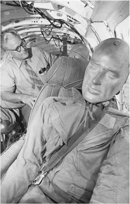
This aircraft test site was the only such testing facility in the coun­try capable of slinging a full-scale aircraft into the ground, similar to the way it would impact during a real crash. To add to the realism, many of the aircraft dropped during these tests carried instrumented anthropo­morphic test dummies to simulate passengers and crew. The gantry was able to support aircraft weighing up to 30,000 pounds and drop them from as high as 200 feet above the ground. Each crash was recorded and evaluated using both external and internal cameras, as well as an array of onboard scientific instrumentation.[366]

Since 1974, NASA has conducted crash tests on a variety of aircraft, including high and low wing, single – and twin-engine general-aviation air­craft and fuselage sections, military rotorcraft, and a variety of other aviation and space components. During the 30-year period after the first full-scale crash test in February 1974, this system was employed to conduct 41 crash/ impact tests on full-sized general-aviation aircraft and 11 full-scale rotor – craft tests. It also provided for 48 Wire Strike Protection System (WSPS) Army helicopter qualification tests, 3 Boeing 707 fuselage section verti­cal drop tests, and at least 60 drop tests of the F-111 crew escape module.[367]

The massive amount of data collected in these tests has been used to determine what types of crashes are survivable. More specifically, this information has been used to establish guidelines for aircraft seat design that are still used by the FAA as its standard for certification. It has also contributed to new technologies, such as energy-absorbing seats, and to improving the impact characteristics of new advanced composite mate­rials, cabin floors, engine support fittings, and other aircraft components and equipment.[368] Indeed, much of today’s aircraft safety technology can trace its roots to NASA’s pioneering landing impact research.

Birthing the Testing Techniques

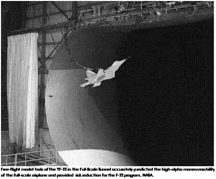
The development and use of free-flying model techniques within the NACA originated in the 1920s at the Langley Memorial Aeronautical Laboratory at Hampton, VA. The early efforts had been stimulated by concerns over a critical lack of understanding and design criteria for methods to improve aircraft spin behavior.[441] Although early aviation pioneers had been frequently using flying models to demonstrate con­cepts for flying machines, many of the applications had not adhered to the proper scaling procedures required for realistic simulation of full – scale aircraft motions. The NACA researchers were very aware that cer­tain model features other than geometrical shape required application of scaling factors to ensure that the flight motions of the model would replicate those of the aircraft during flight. In particular, the require­ments to scale the mass and the distribution of mass within the model were very specific.[442] The fundamental theories and derivation of scaling factors for free-flight models are based on the science known as dimen­sional analysis. Briefly, dynamic free-flight models are constructed so that the linear and angular motions and rates of the model can be readily scaled to full-scale values. For example, a dynamically scaled 1/9-scale model will have a wingspan 1/9 that of the airplane and it will have a weight of 1/729 that of the airplane. Of more importance is the fact that the scaled model will exhibit angular velocities that are three times faster than those of the airplane, creating a potential challenge for a remotely located human pilot to control its rapid motions.

Initial NACA testing of dynamically scaled models consisted of spin tests of biplane models that were hand-launched by a researcher or cat­apulted from a platform about 100 feet above the ground in an airship hangar at Langley Field.[443] As the unpowered model spun toward the ground, its path was tracked and followed by a pair of researchers hold­ing a retrieval net similar to those used in fire rescues. To an observer,

the testing technique contained all the elements of an old silent movie, including the dash for the falling object. The information provided by this free-spin test technique was valuable and provided confidence (or lack thereof) in the ability of the model to predict full-scale behavior, but the briefness of the test and the inevitable delays caused by dam­age to the model left much to be desired.

The free-flight model testing at Langley was accompanied by other forms of analysis, including a 5-foot vertical wind tunnel in which the aerodynamic characteristics of the models could be measured during simulated spinning motions while attached to a motor-driven spinning apparatus. The aerodynamic data gathered in the Langley 5-Foot Vertical Tunnel were used for analyses of spin modes, the effects of various air­plane components in spins, and the impact of configuration changes. The airstream in the tunnel was directed downward, therefore free – spinning tests could not be conducted.[444]

Meanwhile, in England, the Royal Aircraft Establishment (RAE) was aware of the NACA’s airship hangar free-spinning technique and had been inspired to explore the use of similar catapulted model spin tests in a large building. The RAE experience led to the same unsatisfac­tory conclusions and redirected its interest to experiments with a novel 2-foot-diameter vertical free-spinning tunnel. The positive results of tests of very small models (wingspans of a few inches) in the apparatus led the British to construct a 12-foot vertical spin tunnel that became operational in 1932.[445] Tests in the facility were conducted with the model launched into a vertically rising airstream, with the model’s weight being supported by its aerodynamic drag in the rising airstream. The mod­el’s vertical position in the test section could be reasonably maintained within the view of an observer by precise and rapid control of the tun­nel speed, and the resulting test time could be much longer than that obtained with catapulted models. The advantages of this technique were very apparent to the international research community, and the facility features of the RAE tunnel have influenced the design of all other ver­tical spin tunnels to this day.

Birthing the Testing Techniquesturning vanes

test section

documentation

camera

data

acquisition cameras (2 of 8)

honeycomb

This cross-sectional view of the Langley 20-Foot Vertical Spin Tunnel shows the closed-return tun­nel configuration, the location of the drive fan at the top of the facility, and the locations of safety nets above and below the test section to restrain and retrieve models. NASA.

When the NACA learned of the new British tunnel, Charles H. Zimmerman of the Langley staff led the design of a similar tunnel known as the Langley 15-Foot Free-Spinning Wind Tunnel, which became opera­tional in 1935.[446] The use of clockwork delayed-action mechanisms to move the control surfaces of the model during the spin enabled the researchers

to evaluate the effectiveness of various combinations of spin recovery tech­niques. The tunnel was immediately used to accumulate design data for satisfactory spin characteristics, and its workload increased dramatically.

Langley replaced its 15-Foot Free-Spinning Wind Tunnel in 1941 with a 20-foot spin tunnel that produced higher test speeds to support scaled models of the heavier aircraft emerging at the time. Control inputs for spin recovery were actuated at the command of a researcher rather than the preset clockwork mechanisms of the previous tunnel. Copper coils placed around the periphery of the tunnel set up a magnetic field in the tunnel when energized, and the magnetic field actuated a magnetic device in the model to operate the model’s aerodynamic control surfaces.[447]

The Langley 20-Foot Vertical Spin Tunnel has since continued to serve the Nation as the most active facility for spinning experiments and other studies requiring a vertical airstream. Data acquisition is based on a model space positioning system that uses retro-reflective targets attached on the model for determining model position, and results include spin rate, model attitudes, and control positions.[448] The Spin Tunnel has sup­ported the development of nearly all U. S. military fighter and attack aircraft, trainers, and bombers during its 68-year history, with nearly 600 projects conducted for different aerospace configurations to date.

Quest for Guidelines: Tail Damping Power Factor

An empirical criterion based on the projected side area and mass distribution of the airplane was derived in England, and the Langley staff proposed a design criterion in 1939 based solely on the geometry of aircraft tail surfaces. Known as the tail-damping power factor (TDPF), it was touted as a rapid estimation method for determining whether a new design was likely to comply with the minimum requirements for safety in spinning.[508]

The beginning of World War II and the introduction of a new Langley 20-Foot Spin Tunnel in 1941 resulted in a tremendous demand for spin­ning tests of high-priority military aircraft. The workload of the staff increased dramatically, and a tremendous amount of data was gath­ered for a large number of different configurations. Military requests for spin tunnel tests filled all available tunnel test times, leaving no time for general research. At the same time, configurations were tested with

radical differences in geometry and mass distribution. Tailless aircraft with their masses distributed in a primarily spanwise direction were introduced, along with twin-engine bombers and other unconventional designs with moderately swept wings and canards.

In the 1950s, advances in aircraft performance provided by the introduction of jet propulsion resulted in radical changes in aircraft configurations, creating new challenges for spin technology. Military fighters no longer resembled the aircraft of World War II, as the intro­duction of swept wings and long, pointed fuselages became common­place. Suddenly, certain factors, such as mass distribution, became even more important, and airflow around the unconventional, long fuselage shapes during spins dominated the spin behavior of some configurations. At the same time, fighter aircraft became larger and heavier, resulting in much higher masses relative to the atmospheric density, especially during flight at high altitudes.