Category AERONAUTICS

Toward Transatmospheric Flight: From V-2 to the X-51

T. A. Heppenheimer

The expansion of high-speed aerothermodynamic knowledge enabled the attainment of hypersonic speeds, that is, flight at speeds of Mach 5 and above. Blending the challenge of space flight and flight within the atmosphere, this led to the emergence of the field of transatmospherics: systems that would operated in the upper atmosphere, transitioning from lifting flight to ballistic flight, and back again. NACA-NASA research proved essential to mastery of this field, from the earliest days of blunt body reentry theory to the advent of increasingly sophisticated transatmo­spheric concepts, such as the X-15, the Shuttle, the X-43A, and the X-51.

O

N DECEMBER 7, 1995, the entry probe of the Galileo spacecraft plunged downward into the atmosphere of Jupiter. It sliced into the planet’s hydrogen-rich envelope at a gentle angle and entered at Mach 50, with its speed of 29.5 miles per second being four times that of a return to Earth from the Moon. The deceleration peaked at 228 g’s, equiv­alent to slamming from 5,000 mph to a standstill in a single second. Yet the probe survived. It deployed a parachute and transmitted data from its onboard instruments for nearly an hour, until overwhelmed by the increas­ing pressures it encountered within the depths of the Jovian atmosphere.[544]

The Galileo probe offered dramatic proof of how well the National Aeronautics and Space Administration (NASA) had mastered the field of hypersonics, particularly the aerothermodynamic challenges of dou­ble-digit high-Mach atmospheric entries. That level of performance was impressive, a performance foreshadowed by the equally impressive (cer­tainly for their time) earlier programs such as Mercury, Gemini, Apollo, Pioneer, and Viking. But NASA had, arguably, an even greater challenge before it: developing the technology of transatmospheric flight—the abil­ity to transit, routinely, from flight within the atmosphere to flight out

into space, and to return again. It was a field where challenge and con­tradiction readily mixed: a world of missiles, aircraft, spacecraft, rock­ets, ramjets, and combinations of all of these, some crewed by human operators, some not.

Transatmospheric flight requires mastery of hypersonics, flight at speeds of Mach 5 and higher in which aerodynamic heating predomi­nates over other concerns. Since its inception after the Second World War, three problems have largely driven its development.

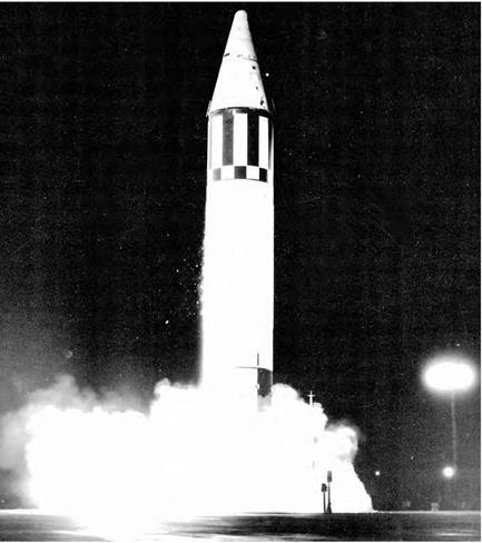
First, the advent of the nuclear-armed intercontinental ballistic mis­sile (ICBM), during the 1950s, brought the science of reentry physics and took the problem of thermal protection to the forefront. Missile nose cones had to be protected against the enormous heat of their atmo­sphere entry. This challenge was resolved by 1960.

Associated derivative problems were dealt with as well, including that of protecting astronauts during demanding entries from the Moon. Maneuvering hypersonic entry became a practical reality with the Martin SV-5D Precision Recovery Including Maneuvering Entry (PRIME) in

1967. In 1981, the Space Shuttle introduced reusable thermal protec­tion—the "tiles”—that enabled its design as a "cool” aluminum air­plane rather than one with an exotic hot structure. Then in 1995, the Galileo mission met demands considerably greater than those of a return from the Moon.

A second and contemporary problem, during the 1950s, involved the expectation that flight speeds would increase essentially without limit. This hope lay behind the unpiloted air-launched Lockheed X-7, which used a ramjet engine and ultimately reached Mach 4.31. There also was the rocket-powered and air-launched North American X-15, the first transatmospheric aircraft. One X-15 achieved Mach 6.70 (4,520 mph) in October 1967. This set a record for winged hypersonic flight that stood until the flight of the Space Shuttle Columbia in 1981. The X-15 introduced reaction thrusters for aircraft attitude, and they subse­quently became standard on spacecraft, beginning with Project Mercury. But the X-15 also used a "rolling tail” with elevons (combined eleva­tors and ailerons) in the atmosphere and had to transition to and from space flight. The flight control system that did this later flew aboard the Space Shuttle. The X-15 also brought the first spacesuit that was flex­ible when pressurized rather than being rigid like an inflated balloon. It too became standard. In aviation, the X-15 was first to use a simula­tor as a basic tool for development, which became a critical instrument

for pilot training. Since then, simulators have entered general use and today are employed with all aircraft.[545]

A third problem, emphasized during the era of President Ronald Reagan’s Strategic Defense Initiative (SDI) in the 1980s, involved the prospect that hypersonic single-stage-to-orbit (SSTO) air-breathing vehicles would shortly replace the Shuttle and other multistage rocket – boosted systems. This concept depended upon the scramjet, a variant of the ramjet engine that sustained a supersonic internal airflow to run cool. But while scramjets indeed outperformed conventional ramjets and rockets, their immaturity and higher drag made their early application as space access systems impossible. The abortive National Aero-Space Plane (NASP) program consumed roughly a decade of development time. It ballooned enormously in size, weight, complexity, and cost as time progressed and still lacked, in the final stages, the ability to reach orbit. Yet while NASP faltered, it gave a major boost to computational fluid dynamics, which use supercomputers to study airflows in aviation. This represents another form of simulation that also is entering gen­eral use. NASP also supported the introduction of rapid-solidification techniques in metallurgy. These enhance alloys’ temperature resistance, resulting in such achievements as the advent of a new type of titanium that can withstand 1,500 degrees Fahrenheit (°F).[546] Out of it have come more practical and achievable concepts, as evidenced by the NASA X-43 program and the multiparty X-51A program of the present.

Applications of practical hypersonics to the present era have been almost exclusively within reentry and thermal protection. Military hyper­sonics, while attracting great interest across a range of mission areas, such as surveillance, reconnaissance, and global strike, has remained the stuff of warhead and reentry shape research. Ambitious concepts for transatmospheric aircraft have received little support outside the labo­ratory environment. Concepts for global-ranging hypersonic "cruisers” withered in the face of the cheaper and more easily achievable rocket.

The Advent of Digital Flight Control Systems

Digital flight control systems were more nuanced still.[702] Analog com­puters calculate solutions simultaneously, thus producing an instanta­neous output for any input. Digital computers, although more precise than analog, calculate solutions in sequence, thus introducing a time delay between the input and the output, often referred to as "transport delay.” Early digital computers were far too slow to function in a real­time, flight control feedback system and could not compute the required servo commands fast enough to control the aircraft motions. As digital computation become faster and faster, control system designers gave serious attention to using them in aircraft flight control systems. NASA Dryden undertook the modification and flight-testing of a Vought F-8C Crusader Navy fighter to incorporate a digital fly-by-wire (DFBW) control system, based on the Apollo Guidance Computer used in the Apollo space capsule. The F-8 DFBW’s first flight was in 1972, and the test program completed 248 DFBW flights before its retirement at the end of 1985.

It constituted a very bold and aggressive research program. The F-8 used redundant digital computers and was the first airplane relying solely on fly-by-wire technology for all of its flights. (Earlier FBW efforts, such as the AF F-4 Survivable Flight Control System, used a mechani­cal backup system for the first few flights.) NASA’s F-8 DFBW program

not only set the stage for future military and civil digital flight control systems and fly-by-wire concepts, it also established the precedent for the operational procedures and built-in-test (BIT) requirements for this family of flight control systems.[703] The ground-testing and general oper­ating methods that were established by NASA DFRC in order to ensure safety of their F-8 DFBW airplane are still being used by most modern military and civilian airplanes.

After the completion of the basic digital FBW demonstration pro­gram, the F8 DFBW airplane was used for additional research testing, such as identifying the maximum allowable transport delay for a digital system to avoid pilot-induced oscillations. This is a key measurement in determining whether digital computations are fast enough to be used successfully in a control system. (The number turned out to be quite small, on the order of only 100 to 120 milliseconds.) The stimulus for this research was the PIO experienced by Shuttle pilot-astronaut Fred Haise during the fifth and last of the approach and landing tests flown at Edwards by the Space Shuttle orbiter Enterprise on October 26, 1977. Afterward, the Shuttle test team asked the DFBW test team if they could run in-flight simulations of the Shuttle using the F-8 DFBW testbed, to determine the effect of transport delays upon control response. During this follow-on research-testing phase, NASA Dryden Flight Research Center pilot John Manke experienced a dramatic, and very scary, land­ing. As he touched down, he added power to execute a "touch and go” to fly another landing pattern. But instead of climbing smoothly away, the F-8 began a series of violent pitching motions that Manke could not control. He disengaged the test system (which then reverted to a digital FBW version of the basic F-8 control system) just seconds before hit­ting the ground. The airplane returned to normal control, and the pilot landed safely. The culprit was an old set of control laws resident in the computer memory that had never been tested or removed. A momen­tary high pitch rate during the short ground roll had caused the air­plane to automatically switch to these old control laws, which were later

The Advent of Digital Flight Control Systems

The Ling-Temco-Vought A-7D DIGITAC testbed was the first U. S. Air Force airplane with a digital flight control system. USAF.

determined to be unflyable.[704] This event further reinforced the need for extensive validation and verification tests of all software used in digi­tal flight control systems, no matter how expensive or time-consuming.

In 1975, the Air Force began its own flight-testing of a digital flight control system, using a Ling-Temco-Vought A-7D Corsair II attack air­craft modified with a digital flight control system (dubbed DIGITAC,) to duplicate the handling qualities of the analog Command Augmentation System of the baseline A-7D aircraft. As well, testers intended to evalu­ate several multimode features.

The model-following system was enhanced to allow several mod­els to be selected in flight. The objective was to determine if the pilot might desire a different model response during takeoff and landing, for example, than during air-to-air or air-to-ground gunnery maneuvers. The program was completed successfully in only 1 year of testing, primar­ily because the airplane was equipped with the standard A-7D mechan­ical backup system. The airplane used two digital computers that were continuously compared. If a disagreement occurred, the entire system would disengage, and the backup mechanical system was used to safely recover the airplane. The pilot also had a paddle switch on the stick that

immediately disconnected the digital system. This allowed software changes to be made quickly and safely and avoided most of the neces­sary, but time-consuming, preflight safety procedures that were associ­ated with NASA’s F-8 DFBW program.[705]

One of the more challenging flight control system designs was associ­ated with the Grumman X-29 research airplane. The X-29 was designed to demonstrate the advantages of a forward-swept wing (FSW), along with other new technologies.

The airplane would fly with an unusually large level of pitch instabil­ity. The F-16, while flying at subsonic speeds, had a negative static mar­gin of about 6 percent. The X-29 static margin was 35 percent unstable. (In practical terms, this meant that the divergence time to double ampli­tude was about half a second, effectively meaning that the airplane would destroy itself if it went out of control before the pilot could even recog­nize the problem!) This level of instability required extremely fast control surface actuators and state-of-the-art computer software. The primary system was a triplex of digital computers, each of which was backed up by an analog computer. A failure of one digital channel did not pre­vent the remaining two digital computers from continuing to function. After two digital channel failures, the system reverted to the three all­analog computers, thus maintaining fail-op, fail-op, fail-safe capability.

After completing the limit-cycle and resonance ground tests men­tioned earlier, plus a lengthy software validation and verification effort, the flight-testing began in 1984 at NASA’s Dryden Flight Research Center.[706] The control system handled the high level of instability quite well, and the test program on two airplanes was very successful, ending in 1992. Although the forward-swept wing concept has not been incorporated in any modern airplanes, the successful completion of the X-29 pro­gram further boosted the confidence in digital FBW control systems.[707]

In recent years, the digital FBW systems have become the norm in military aircraft. The later models of the F-15, F-16, and F/A-18 were

equipped with digital FBW flight control systems. The C-17 Globemaster III airlifter and F-117 Nighthawk stealth fighter performed their first flights with digital FBW systems. The Lockheed Martin F-22 Raptor and F-35 Lightning II Joint Strike Fighter exploit later digital FBW tech­nology. Each has three digital computers and, for added safety, three of each critical component within its control systems. (Such "cross-strap­ping” of the various components allows FOFOFS redundancy.) There are dual-air data systems providing the various state variables that are backed up by an inertial system. The various "survivability” features first examined and demonstrated decades previously with the F-4 SFCS program (wire-routing, separate component locations, etc.) were also included in their basic design.

Aerothermodynamics: Meeting the Heating Challenge

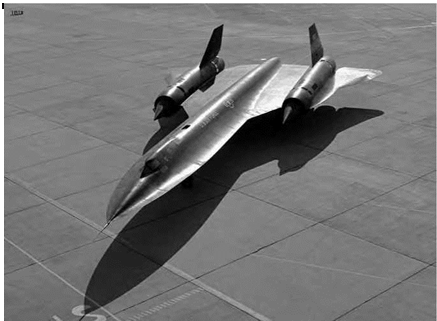
The prediction of structural heating on airplanes flying at hypersonic speeds preceded the actual capability to attain these speeds in con­trolled flight. There were dire predictions of airplanes burning up when they encountered the "thermal thicket,” similar to the dire predictions that preceded flight through the sound barrier. Aerodynamic heating is created by friction of an object moving at very high speed through the atmosphere. Temperatures on the order of 200 degrees Fahrenheit (°F) are generated at Mach 2 (the speed of an F-104 Starfighter of the mid – 1950s), 600 °F at Mach 3 (that of a 1960s SR-71 Blackbird), and 1,200

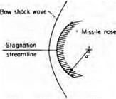
°F at Mach 6 (typical of the X-15). Reentry from orbital speeds (Mach 26—the entry velocity of the Space Shuttle orbiter) will generate tem­peratures of around 2,400 °F. Airplanes or spacecraft that fly in, or reenter, the atmosphere above Mach 2 must be designed to withstand not only aerodynamic forces associated with high Mach number but also the high temperatures associated with aerodynamic heating. The advent of blunt body reentry theory radically transformed the mental image of the spacecraft, from a "pointy” rocket to one having a far more bluff and rounded body. Conceived by H. Julian Allen with the assis­tance of Alfred Eggers of the then-NACA Ames Aeronautical Laboratory (now NASA Ames Research Center), blunt-body design postulated using a blunt reentry shape to form a strong "detached” shock wave that could act to relieve up to 90 percent of the thermal load experienced by a body entering Earth’s atmosphere from space.[749] Such a technical approach was first applied to missile warhead design and the first crewed spacecraft, both Soviet and American. But blunt bodies, for all their commendable thermodynamic characteristics, likewise have high drag and poor entry down-range and cross-range predictability. Tailored higher L/D lifting body and blended wing-body shapes (such as those pioneered by the Air Force Flight Dynamics Laboratory), while offering far better aerodynamic and cross-range performance and predictability, pose far greater cooling chal­lenges. So, too, do concepts for hypersonic air-breathing vehicles. These diverse requirements have stimulated the design and development of sev­eral potential solutions for thermal protection of a vehicle. For purposes of discussion, these concepts are addressed as heat sink structures, abla­tion, hot structures, active cooling, and advanced ceramic protection.

. Direct Numerical Simulation

What of the future of CFD? Most flows of practical interest are turbu­lent flows. Turbulence is still one of the few unsolved problems in clas­sical physics. In the calculation of turbulent flows, we therefore have to model the effect of turbulence. Any turbulence model involves some empirical data, and all models are inaccurate to some greater or lesser degree. The uncertainty in turbulence models is the reason for much uncertainty in the calculation of turbulent flows in computational fluid dynamics. This will continue for years to come. There is, however, an approach that requires no turbulence modeling. Nature creates a tur­bulent flow using the same fundamental principles that are embodied in the Navier-Stokes equations. Indeed, turbulence on its most detailed scale is simply a flow field developed by nature. If one can put enough grid points in the flow, then a Navier-Stokes solution will calculate all the detailed turbulence without the need for any type of model. This is called direct numerical simulation. The key is "enough grid points,” which even for the simplest flow over a flat plate requires millions of points.

Once again, NASA researchers have been leading the way. Calculations made at NASA Ames for flow over a flat plate have required over 10 mil­lion grid points taking hundreds of hours on supercomputers, an indica­tion of what would be required to calculate the whole flow field around a complete airplane using direct numerical simulation. But this is the future, perhaps, indeed, as far as three decades away. By that time, the computational power of computers will have undoubtedly continued to increase many-fold, and, as well, NASA will be continuing to play a leading role in advancing CFD, even as it is today and has in the past.

Johnson Space Center

Johnson Space Center, a product of the "space age,” is NASA’s core cen­ter for human space flight, development of launch vehicles and systems, astronaut training, and human space flight operations. As a Center with significant hardware development and operational responsibilities, Johnson’s activities in analysis methods have been "usually directed to specific problems relating to developing hardware that the Center is responsible for.”[901]

Except for moderate downsizing in the 1980s and minor organiza­tional changes such as separating Structures and Dynamics into two branches, the structures-related organization has been relatively sta­ble over several decades. The Structural Engineering Division (ES) has approximately 120 employees divided into 5 branches: Structures, Dynamics, Thermal, Material, and Mechanisms. The Structures Branch (ES2) has responsibility for structural design, analysis (including com­puter methods), and testing.[902] Johnson has some very significant test facilities, including a tower that can hold a full Apollo or similar-sized

vehicle and subject it to vibration testing.[903] Current directions at Johnson include sustaining activity for the Space Shuttle and the International Space Station (ISS), and new work related to the Orion spacecraft.[904]

With the emphasis on hardware and systems development, rather than on methods development, Johnson has favored the use of computer programs already available when they can meet the need. According to Modlin:

8

Prior to NASTRAN we used the SAMIS program that was developed by JPL for stress and dynamics, our inputs regard­ing NASTRAN were directed to the NASTRAN office at NASA Langley after the program was delivered, but we did not do any development on our own. We and our contractor wanted to use NASTRAN on the Shuttle Orbiter, but required substructuring.

This wasn’t delivered in time [as a NASTRAN capability] so the contractor continued with ASKA. . . . Some programs developed in house relate to: Lunar landing, Apollo Crew Module water landing and flight loads. One more general program that has wide use is NASGRO (formerly FLAGRO), which was devel­oped by Royce Forman. It is a fracture mechanics routine.[905]

Although this paper has not attempted to cover fracture mechanics, it is worth noting that NASGRO, originally developed for space applica­tions, has been enhanced with "many features specifically implemented to suit the needs of the aircraft industry,” because of increasing focus in the Federal Aviation Administration (FAA), NASA, and DOD on safety of aging aircraft.[906]

Other programs developed at Johnson or under Johnson sponsorship include TRASYS (Thermal Radiation Analysis System, 1973), FAMSOR (Frequencies and Modes of Shells Of Revolution, 1974), SNASOR (Static

Nonlinear Analysis of Shells of Revolution, 1974), BUCKY (Plate buck­ling, 1992), and COMPAPP (Composite plate buckling, 1994).[907]

Dynamic Simulation of Controls & Structure (Goddard, 1970s-1990s)

Another important area of spacecraft structural modeling is in the inter­action of control systems with flexible multibody structural systems. In a general sense, this is the spacecraft counterpart to aeroservoelasticity, although the driving mechanisms are very different. Dynamic Simulation of Controls & Structure (DISCOS) was developed in the late 1970s to perform this type of analysis. "The physical system undergoing analy­sis may be generally described as a cluster of contiguous flexible struc­tures (bodies) that comprise a mechanical system, such as a spacecraft. The entire system (spacecraft) or portions thereof may be either spin­ning or nonspinning. Member bodies of the system may undergo large relative excursions, such as those of appendage deployment or rotor/ stator motion. The general system of bodies is, by its inherent nature, a feedback system in which inertial forces (such as those due to centrifu­gal and Coriolis acceleration) and the restoring and damping forces are motion-dependent. . . . The DISCOS program can be used to obtain non­linear and linearized time response of the system, interaction constant forces in the system, total system resonance properties, and frequency domain response and stability information for the system. DISCOS is probably the most powerful computational tool to date for the computer simulation of actively controlled coupled multi-flexible-body systems,” according to the computer program abstract. The program was made available to approved licensees (for $1,000, in 1994) with the caveat that DISCOS " . . . is not easy to understand and effectively apply, but is not

intended for simple problems. The DISCOS user is expected to have extensive working knowledge of rigid-body and flexible-body dynamics, finite-element techniques, numerical methods, and frequency-domain analysis.” DISCOS was used extensively at least into the 1990s for spacecraft modeling.[989] In 1983, a program for bridging DISCOS, NASTRAN, and SAMSAN—a large order control system design program—was also publicly released.[990] A 1987 NASA-funded study by Honeywell (Space and Strategic Avionics Division) out­lined some limitations of DISCOS and other contemporary multi­body dynamics programs and made recommendations for future work in the field.[991] Also in the late 1980s, GSFC began collaborat­ing with a research group at the University of Iowa that was devel­oping similar multibody modeling capabilities for mechanical engineering applications. The National Science Foundation (NSF), U. S. Army Tank Automotive Command, and about 30 other Government and industry laboratories were involved in this project through the Industry/University Cooperative Research Center (I/UCRC) at the University of Iowa. Goals of the I/UCRC were to achieve mutual enhance­ment of capabilities in the modeling, simulation, and control of complex mechanical systems, including man/machine interactions applicable to manufacturing processes.[992]

Making the Electric Jet

Albert C. Piccirillo

Fly-by-wire (FBW) technology pioneered by NASA has enabled the design of highly unconventional airframe configurations. Continuing NASA FBW research has validated integrated digital propulsion and flight control systems. FBW has been applied to civil aircraft, improving their safety and efficiency. Lessons learned from NASA FBW research have been transferred to maritime design, and Agency experts have supported the U. S. Navy in developing digital electronic ship control.

HE EVOLUTION OF ADVANCED AIRCRAFT equipped with comput­erized flight and propulsion control systems goes back a long way and involved many players, both in the United States and interna­tionally. During the Second World War, use of electronic sensors and subsystems began to become pervasive, adding new mission capabili­ties as well as increasing complexity. Autopilots were coupled to flight control systems, and electric trim was introduced. Hydraulically or electrically boosted flight control surfaces, along with artificial feel and stability augmentation systems, soon followed as did electronic engine control systems. Most significantly, the first uses of airborne computers emerged, a trend that soon resulted in their use in aircraft and missiles for their flight and mission control systems. Very early on, there was a realization that traditional mechanical linkages between the cockpit flight controls and the flight control surfaces could be replaced by a computer – controlled fly-by-wire (FBW) approach in which electric signals were trans­mitted from the pilot’s controls to the control surface actuators by wire. This approach was understood to have the potential to reduce mechani­cal complexity, lower weight, and increase safety and reliability. In addi­tion, the processing power of the computer could be harnessed to enable unstable aircraft designs to be controlled. Properly tailored, these unsta­ble designs could enable new aircraft concepts to be implemented that could fully exploit the advantages of active flight control. Such aircraft

would be more maneuverable and lighter, have better range, and also allow for the fully integrated control of aircraft, propulsion, navigation, and mission systems to optimize overall capability.

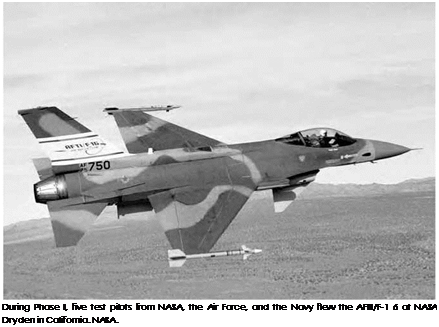
Two significant events unfolded during the 1960s that fostered the move to electronic flight control systems. The space race was a major influence, with most space systems relying on computerized fly-by-wire control systems for safe and effective operation. The Vietnam war pro­vided a strong impetus for the development of more survivable aircraft systems as well for new aircraft with advanced performance features. The National Aeronautics and Space Administration (NASA) and the Air Force aggressively responded to these challenges and opportunities, resulting in the rapid transition of digital computer technology from the space program into aircraft fly-by-wire applications as exemplified by the Digital Fly-By-Wire F-8 and the AFTI/F-16 research programs. Very quickly after, a variety of flight research programs were implemented. These programs provided the basis for development and fielding of numerous military and civil aircraft equipped with advanced digital fly­by-wire flight control systems. On the civil aviation side, safety has been improved by preventing aircraft flight envelope limitations from being exceeded. Operating efficiency has been greatly enhanced and major weight savings achieved from fly-by-wire and related electronic flight control system components. Integrated flight and propulsion control systems precisely adjust throttles and fuel tank selections. Rudder trim drag because of unbalanced engine thrust is reduced. Fuel is automati­cally transferred between tanks throughout the aircraft to optimize cen­ter of gravity during cruise flight, minimizing elevator trim drag. In the case of advanced military aircraft, electronically controlled active flight, propulsion, and mission systems have been fully integrated, providing revolutionary improvements in capabilities. Significantly, new highly unstable aircraft configurations are providing unprecedented levels of mission performance along with very low radar signatures, capabilities that have been enabled by exploiting digital fly-by-wire flight and pro­pulsion control systems pioneered in NASA.

F-16 CCV

By the mid-1970s, the Air Force Flight Dynamics Laboratory had initiated a Control Configured Vehicle flight research program to investigate the use of nonconventional (often called "decoupled”) movements of aircraft flight control surfaces to enable maneuvers in one plane without move­ment in another. An example of such a maneuver would be a wings-level turn without having to bank the aircraft. The very first General Dynamics YF-16 technology demonstrator aircraft (USAF serial No. 72-1567) was selected for modification. Rebuilt in December 1975 and fitted with twin
vertical canards underneath the air intake, it became known as the F-16/CCV. Its flight controls were modified to enable the wing trail­ing edge flaperons to move in combination with the all-moving stabi – lator. In addition, the fuel system in the YF-16 was modified to enable the aircraft center of gravity to be adjusted in flight by transferring fuel between tanks, thus allowing the stability of the aircraft to be varied. The YF-16/CCV flew for the first time on March 16, 1976, piloted by GD test pilot David J. Thigpin. On June 24, 1976, while being flown by David Thigpin, it was seriously damaged in a crash landing. Engine power had been lost on final approach, and the landing gear collapsed in the sub­sequent hard landing. Repairs to the aircraft would take over 6 months. The F-16 CCV returned to flight in the spring of 1977. It would complete 87 flights and 125 flying hours before the research program ended, with the last flight F-16 CCV flight on June 30, 1977.[1178]

Подпись: 10The F-16 CCV anticipated CCV flight-test approaches that were soon undertaken by a number of foreign countries. Flight research projects in Germany, the U. K., and Japan converted existing military aircraft into CCV testbeds. Fitted with computer-controlled fly-by-wire flight control systems, these projects provided experience and insights that enabled these countries to incorporate fly-by-wire flight control into their next generations of advanced civil and military aircraft. These foreign CCV projects are discussed in a separate section of this report. Experience gained with the F-16 CCV served as the basis for the subsequent Flight Dynamics Laboratory AFTI/F-16 program, which would yield valuable insights into many issues associated with developing advanced DFBW flight control systems and result in significantly improved capabilities being incorporated into U. S. military aircraft.

X-29

The Grumman X-29 research aircraft played a very interesting role in the evolution of modern fly-by-wire flight control systems. Exotic in appearance, with its forward-swept wings and large movable canard control surfaces, the X-29 was highly unstable about the longitudinal axis with a static stability margin of -35 percent. This level of instability probably indicates that the X-29 represents the most unstable piloted aircraft that has ever been successfully flown. Not only did it fly, but it also demonstrated good controllability at very high angles of attack. This degree of success was only possible through the use of a very advanced fly-by-wire flight control system that employed a combination of both digital computers in the primary system and analog computers in the backup system. The program began in 1977, with the Defense Advanced Research Projects Agency (DARPA) and the Air Force Flight Dynamics Laboratory jointly soliciting industry proposals for a research aircraft designed to investigate the forward-swept wing concept in a high-per­formance aircraft application. In December 1981, Grumman Aircraft

Подпись:
was selected to build two aircraft, which were designated X-29. The most unique and visually obvious aspect of the design was the forward – swept wings that incorporated a thin supercritical airfoil, but there were many other areas of the X-29 design that embodied advanced tech­nology. The aircraft used advanced composite materials and unusual construction approaches. Its control system made use of variable cam­ber wing surfaces, aft fuselage-mounted strake flaps, fully movable canards mounted on the sides of the engine inlets, and a computerized fly-by-wire flight control system to maintain control of the otherwise highly unstable aircraft.[1221]

In constructing the X-29s, Grumman used the forward fuselage and nose landing gear from two Northrop F-5A fighters. Control surface actuators and the main landing gear came from the F-16. The unique aspect of the X-29 airframe, its forward-swept wing, was developed by Grumman. Because of the major differences between the X-29s and the F-5As, the modified aircraft were assigned new USAF serial numbers, becoming 82-0003 and 82-0049. The main difference between the two

X-29s was the emergency spin parachute system mounted at the base of the rudder on the second aircraft. The X-29 flight research program was conducted by the NASA Dryden Flight Research Center in two phases and included participation by the Air Force Flight Test Center and the Grumman Corporation.[1222] The joint NASA-Air Force portion of the X-29 test program extended from 1984 to 1991; the Air Force conducted a follow-on investigation of vortex flow control (VFC) that lasted into 1992.

Подпись: 10The X-29’s thin supercritical forward-swept wing presented signif­icant design challenges. The typical stall pattern of an aft-swept wing, from wingtip to root, is reversed for a forward-swept wing, which stalls from the root to the tip. The aerodynamic lift forces on the outer por­tions of a forward-swept wing produce a twisting moment that tends to force the leading edge further upward. This increases the angle of attack at the wingtips, causing even further twisting that, if uncontrolled, can lead to structural failure of the wing, a phenomenon known as aero – elastic divergence. To deal with this problem, Grumman made use of state-of-the-art composite materials in designing the wing external skin, which it laminated in a way that produced an inherent coupling between wing bending and torsion loads, a concept known as aeroelastic tailor­ing. At increasing angles of attack (higher lift), the structural character­istics incorporated into composite laminates were designed to ensure that the wing twisted to counter the upward twist produced by aerodynamic loads. The key to the design was balancing the aerodynamic aspects of the wing’s configuration with the structural characteristics of the composite laminate to control potential aeroelastic divergence. The wing substruc­ture and the basic airframe itself were made of aluminum and titanium.[1223]

The X-29 featured an unusual combination of flight control sur­faces. These consisted of forward-mounted canards that contributed positive lift and provided primary control about the pitch axis. Wing flaperons (combination flaps and ailerons) could change the camber of the wing and also functioned as ailerons for roll control. The actua­tors used to control wing camber were mounted externally in stream­lined fairings at the trailing edge of the wing because of the thinness of the supercritical airfoil. The strake flaps on each side of aft fuselage augmented the canards, proving additional pitch control. The control sur­faces were electronically linked to a triple-redundant digital fly-by-wire
flight control system (with analog backup) that provided artificial sta­bility necessary for controlling the inherently unstable forward-swept wing, close-coupled canard design used on the X-29. Each of the three digital flight control computers had an analog backup. If one of the digital computers failed, the remaining two took over. If two of the digital computers failed, the flight control system switched to the ana­log mode. If one of the analog computers failed, the two remaining ana­log computers took over.[1224]

Подпись: 10Grumman chief test pilot Charles A. "Chuck” Sewell flew the first X-29 at Edwards AFB on December 14, 1984.[1225] During the Phase I research effort, X-29 aircraft No. 1 was used exclusively, flying 242 times. Its wingtips remained unstalled up to the 21-degree angle of attack allowed in Phase I testing. This limitation was due to the fact that an anti-spin parachute was not installed on the aircraft. The aeroelas – tic tailored wing prevented structural divergence of the wing, and the digital flight control system functioned safely and reliably. Flight con­trol laws and control surface effectiveness combined to provide good pilot handling qualities during maneuvering flight. The aircraft’s supercritical airfoil contributed to enhanced cruise and maneuver performance in the transonic regime.[1226] However, overall drag reduc­tion was not as great as had been predicted for the configuration. On December 13, 1985, with NASA test pilot Steve Ishmael at the con­trols, the X-29 became the first aircraft with a forward-swept wing to fly beyond the speed of sound, reaching Mach 1.03 in level flight.[1227] Other test pilots who flew the X-29 during Phase I of the joint test program were NASA test pilot Rogers Smith, Lt. Col. Theodore "Ted” Wierzbanowski and Maj. Harry Walker from the Air Force, and Navy Cdr. Ray Craig.

Подпись: 10The second X-29 aircraft, modified to incorporate an anti-spin para­chute and its deployment mechanism, was used during Phase II test­ing to investigate the aircraft’s high-angle-of-attack characteristics and the potential usefulness of the forward-swept wing and canard config­uration on military fighter plane designs. First flown on May 23, 1989, it would eventually fly 120 research flights and demonstrate control and maneuvering qualities that were better in many cases than the pre­dictions derived from computational methods and simulation models. NASA, Air Force, and Grumman project pilots reported that the X-29 had excellent control response up to angles of attack of 45 degrees, with limited controllability still available at up to 67 degrees angle of attack. Phase II flight-testing defined an allowable X-29 flight envelope that extended to Mach 1.48, an altitude of just over 50,000 feet, an angle of attack of up to 50 degrees at 1 g and 35 degrees at airspeeds up to 300 knots. Much of the X-29’s high-angle-of-attack capability was attributed to the quality of the flight control laws that were cooperatively devel­oped by NASA and the Air Force. These had initially been developed using results obtained from extensive wind tunnel testing and predic­tions derived from radio-controlled flight tests of a 22-percent scale drop model at NASA Langley Research Center.[1228] Flight control system engi­neers at NASA Dryden and the Air Force Flight Test Center at Edwards used these as the basis for detailed flight control system design. This design used a combination of pitch rate and angle of attack in develop­ing the longitudinal control laws. Selectable gain was included in the flight control system design, and this was used by the X-29 test pilots during flying qualities assessments and evaluations of the effects of control law gain changes at higher angles of attack. Prior to the start of flight-testing, wing rock was estimated to restrict the available angle of attack to less than about 35 degrees. However in flight-testing, wing rock amplitude was found to be less than half of what had been predicted, allowing the roll rate to aileron gain to be lowered to one-fourth of the value that had been derived from preflight data using the subscale free flight model. The available flight envelope was extended to 67 degrees angle of attack at 1 g. Maneuvering flight about all axes was cleared up to an angle of attack of 45 degrees in 1 g flight. The reduced wing rock that had been observed in flight was apparently due to higher roll
damping and increased aileron control power for large aileron deflections.[1229]

Подпись: 10Preflight predictions of the X-29’s pitch capabilities matched flight – test results up through 40 degrees angle of attack. Differences in nose – up pitching moment above an angle of attack of 40 degrees were found to require more canard deflection than predicted. Large yaw asymme­tries led to several instances in which the aircraft tended to stabilize at very high nose-up pitch angles during maneuvers at angles of attack above 50 degrees, with the aircraft at an aft center of gravity. Modifications to pro­vide additional nose-down pitch authority were not possible because of physical limits on canard deflection. Maximum pitch rates were limited by the high level of static instability inherent in the X-29 design and control surface rate limits. New actuators with at least a 50-percent higher actu­ation rate would have been required to achieve pitch rates comparable to those of an operational fighter like the F/A-18. The full wingspan flaper – ons were found to provide good roll control that was not affected by the fact that the X-29 did not use wing leading-edge maneuvering flaps. Pilot – selectable variable gain capability was used during examination of air­plane stability and maneuverability. Basic fighter maneuvers were flown, and roll and yaw gains were increased to improve roll performance. A gain that provided maximum rudder authority resulted in the best pilot com­ments. Roll coordination was better than anticipated, with rudder effec­tiveness also higher than preflight predictions at angles of attack between 20 and 40 degrees. Yaw asymmetries developed above 40 degrees angle of attack. Diminished aileron and rudder power was not sufficient to over­power these asymmetries. Increasing gain further produced rudder sat­uration, resulting in uncoordinated turns, a result that was disliked by test pilots, even though this actually resulted in better roll performance.[1230]

Flight-test data from Phase II, the high-angle-of-attack and mili­tary utility phase of the X-29 program, satisfied the program’s primary objective. The technologies demonstrated in the program had poten­tial to improve future fighter aircraft mission performance, and the forward-swept wings/movable canard configuration provided excel­lent control response at up to 45 degrees angle of attack. Very impor­tantly, the X-29A program provided a significant pool of knowledge that
was very useful background for fine-tuning ground-based predictive techniques for high-angle-of-attack aircraft.[1231] One significant poten­tial safety issue with the flight control system, the danger of sensor selection thresholds being set too wide, was discovered during the X-29 test program. The flight control system used three sources of air data in its computations. These air data sources were the nose probe and two probes mounted one on each side of the forward fuselage. The selection algorithm in the flight control system used the data from the nose probe as the primary source, provided it was within some threshold of the data from both side probes. However, the data selection threshold was inten­tionally large to accommodate known data errors in certain flight modes because of the position of the side sensors in the airflow. Long after the start of flight-testing, ground simulation revealed that the nose probe could, in some circumstances, furnish erroneous information at very low flight speeds, causing the X-29 to go out of control. Although this fault was successfully identified through ground simulation, 162 flights had already been flown before it was detected and corrected.[1232]

Подпись: 10In 1992, the Air Force began a follow-on program with X-29 No. 2 that investigated the use of vortex flow control as a means of providing increased aircraft control at very high angles of attack, at which normal rudder control is ineffective. Wind tunnel tests had showed that injec­tion of air into the vortexes coming off the nose of the aircraft would change the direction of vortex flow. The forces created on the nose of the aircraft could be used to control directional (yaw) stability. The second X-29 aircraft was modified to incorporate two high-pressure nitrogen tanks, related control valves with two small nozzle jets on the forward upper portion of the nose. The nozzles injected air into the vortexes, which flowed off the nose of the aircraft at high angles of attack. From May to August 1992, 60 test flights were flown. Data from these flights were used to determine that VFC was more effective than expected in generating yaw forces, but it was less successful in providing control when sideslip was present, and it did little to decrease roll oscillations.[1233] The two X-29 aircraft flew a total of 436 flights, 254 by the first, and 182 by the second. The former is exhibited at the National Museum of the

Подпись: The X-31 aircraft, showing thrust vectoring paddles. NASA. Подпись: 10

United States Air Force, while the latter remained at Edwards and is on exhibit at the Dryden Flight Research Center.[1234]

Aircraft Energy Efficiency Program

Approved in 1975 and begun in 1976, the Aircraft Energy Efficiency (ACEE) program was managed by NASA and funded through 1983, as yet another round of research and development activities were put in work to improve the state of the art of aircraft structural and propulsion design. And once again, the program was aimed at pushing the technological envelope to see what might be possible. Then, based on that information, new Government regulations could be enacted, and the airline industry could decide if the improvements would offer a good return on its investment. The answer, as it turned out, was an enthusiastic yes, as the overall results of the pro­gram led directly to the introduction of the Boeing 757 and 767.[1307]

Driving this particular program was the rapid increase in fuel costs since 1973 and the accompanying energy crisis, which was brought on by the Organization of Arab Petroleum Exporting Countries’ decision to embargo all shipments of oil to the United States. This action began in October 1973 and continued to March 1974. As a result of this and other economic influences, the airlines saw their fuel prices as a per­centage of direct operating costs rise from 25 percent to as high as 50 percent within a few weeks. With the U. S. still vulnerable to a future oil embargo, along with general concerns about an energy shortage, the

Federal Government reacted by ordering NASA to lead an effort to help find ways for airlines to become more profitable. Six projects were ini­tiated under the ACEE program, three of which had to do with the air­craft structure and three of which involved advancing engine technology. The aircraft projects included Composite Structures, Energy Efficient Transport, and Laminar Flow Control. The propulsion technology proj­ects included Engine Component Improvement, Energy Efficient Engine, and Advanced Turboprop—all three of which are detailed next.[1308]