Category AERONAUTICS

U. K. Jaguar ACT

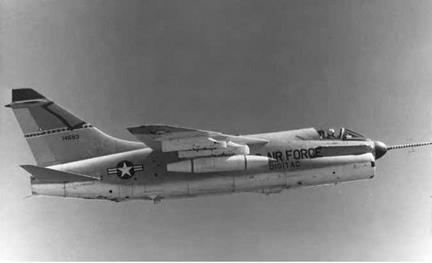
In the U. K., the Royal Aircraft Establishment began an effort ori­ented to producing a CCV testbed in 1977. For this purpose, an Anglo – French Jaguar strike fighter was modified by British Aerospace (BAe) to prove the feasibility of active control technology. Known as the Jaguar Active Control Technology (ACT), the aircraft’s mechanical flight control system was entirely removed and replaced with a quad-redundant digital fly-by-wire control system that used electrical channels to relay instructions to the flight control surfaces. The initial flight of the Jaguar ACT with the digital FBW system was in October 1981. As with the CCV F-104G, ballast was added to the aft fuselage to move the center of gravity aft and destabilize the aircraft. In 1984, the Jaguar ACT was fitted with rounded oversized leading-edge strakes to move the center of lift of the aircraft forward, further contributing to pitch instability. It first flew in this configuration in March 1984. Marconi developed the Jaguar ACT flight control system. It included an optically coupled data transmission link that was essentially similar to the one that they had developed for the U. S. Air Force YC-14 program (an interesting example of the rapid proliferation of advanced aerspace technology between nations).[1218]

Flight-testing began in 1981, with the test program ending in 1984 after 96 flights.[1219]

Advancing Propulsive Technology

James Banke

Подпись: ПEnsuring proper aircraft propulsion has been a powerful stimulus. In the interwar years, the NACA researched propellers, fuels, engine cool­ing, supercharging, and nacelle and cowling design. In the postwar years, the Agency refined gas turbine propulsion technology. NASA now leads research in advancing environmentally friendly and fuel-con­serving propulsion, thanks to the Agency’s strengths in aerodynamic and thermodynamic analysis, composite structures, and other areas.

E

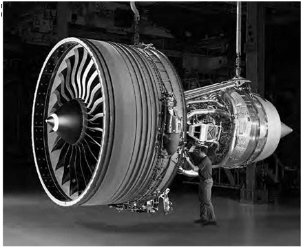
ACH DAY, OUR SKIES FILL with general aviation aircraft, business jets, and commercial airliners. Every 24 hours, some 2 million passen­gers worldwide are moved from one airport to the next, almost all of them propelled by relatively quiet, fuel-efficient, and safe jet engines.[1291]

And no matter if the driving force moving these vehicles through the air comes from piston-driven propellers, turboprops, turbojets, turbofans— even rocket engines or scramjets—the National Aeronautics and Space Administration (NASA) during the past 50 years has played a significant role in advancing that propulsion technology the public counts on every day.

Many of the advances seen in today’s aircraft power-plants can trace their origins to NASA programs that began during the 1960s, when the Agency responded to public demand that the Government apply major resources to tackling the problems of noise pollution near major airports. Highlights of some of the more noteworthy research programs to reduce noise and other pollution, prolong engine life, and increase fuel efficiency will be described in this case study.

But efforts to improve engine efficiency and curb unwanted noise actu­ally predate NASA’s origins in 1958, when its predecessor, the National Advisory Committee for Aeronautics (NACA), served as the Nation’s pre­eminent laboratory for aviation research. It was during the 1920s that

Подпись: 11 Advancing Propulsive Technology

the NACA invented a cowling to surround the front of an airplane and its radial engine, smoothing the aerodynamic flow around the aircraft while also helping to keep the engine cool. In 1929, the NACA won its first Collier Trophy for the breakthrough in engine and aerodynamic technology.[1292]

During World War II, the NACA produced new ways to fix problems discovered in higher-powered piston engines being mass-produced for wartime bombers. NACA research into centrifugal superchargers was particularly useful, especially on the R-1820 Cyclone engines intended for use on the Boeing B-17 Flying Fortress, and later with the Wright R-3350 Duplex Cyclone engines that powered the B-29.

Basic research on aircraft engine noise was conducted by NACA engineers, who reported their findings in a paper presented in 1956 to the 51st Meeting of the Acoustical Society of America in Cambridge, MA. It would seem that measurements backed up the prediction that the noise level of the spinning propeller depended on several variables,
including the propeller diameter, how fast it is turning, and how far away the recording device is from the engine.[1293]

Подпись: 11As the jet engine made its way from Europe to the United States and designs for the basic turboprop, turbojet, and turbofan were refined, the NACA during the early 1950s began one of the earliest noise-reduction programs, installing multitube nozzles of increasing complexity at the back of the engines to, in effect, act as mufflers. These engines were tested in a wind tunnel at Langley Research Center in Hampton, VA. But the effort was not effective enough to prevent a growing public sentiment that commercial jet airliners should be seen and not heard.

In fact, a 1952 Presidential commission chaired by the legendary pilot James H. Doolittle predicted that aircraft noise would soon turn into a problem for airport managers and planners. The NACA’s response was to form a Special Subcommittee on Aircraft Noise and pursue a three – part program to understand better what makes a jet noisy, how to quiet it, and what, if any, impact the noise might have on the aircraft’s structure.[1294]

As the NACA on September 30, 1958, turned overnight into the National Aeronautics and Space Administration on October 1, the new space agency soon found itself with more work to do than just beating the Soviet Union to the Moon.

Advanced Subsonic Technology Program and UEET

Подпись: 12NASA started a project in the mid-1990s known as the Advanced Subsonic Technology program. Like HSR before it, the AST focused heavily on reducing emissions through new combustor technology. The overall objective of the AST was to spur technology innovation to ensure U. S. leadership in developing civil transport aircraft. That meant lowering NOx emissions, which not only raised concern in local airport com­munities but also by this time had become a global concern because of potential damage to the ozone layer. The AST sought to spur the devel­opment of new low-emissions combustors that could achieve at least a 50-percent reduction in NOx from 1996 International Civil Aviation Organization standards. The AST program also sought to develop tech­niques that would better measure how NOx impacts the environment.[1417]

GE, P&W, Allison Engines, and AlliedSignal engines all participated in the project.[1418] Once again, the challenge for these companies was to con­trol combustion in such a way that it would minimize emissions. This required carefully managing the way fuel and air mix inside the combustor to avoid extremely hot temperatures at which NOx would be created, or at least reducing the length of time that the gases are at their hottest point.

Ultimately the AST emissions reduction project achieved its goal of reducing NOx emissions by more than 50 percent over the ICAO stan­dard, a feat that was accomplished not with actual engine demonstrators but with a "piloted airblast fuel preparation chamber.”[1419]

Подпись: 12Despite their relative success, however, NASA’s efforts to improve engine efficiency and reduce emissions began to face budget cuts in 2000. Funding for NASA’s Atmospheric Effects of Aviation project, which was the only Government program to assess the effects of aircraft emissions at cruise altitudes on climate change, was canceled in 2000.[1420] Investments in the AST and the HSR also came to an end. However, NASA did manage to salvage parts of the AST aimed at reducing emissions by rolling those projects into the new Ultra Efficient Engine Technology program in 2000.[1421]

UEET was a 6-year, nearly $300 million program managed by NASA Glenn that began in October 1999 and included participation from NASA Centers Ames, Goddard, and Langley; engine companies GE Aircraft Engines, Pratt & Whitney, Honeywell, Allison/Rolls Royce, and Williams International; and airplane manufacturers Boeing and Lockheed Martin.[1422]

UEET sought to develop new engine technologies that would dramat­ically increase turbine performance and efficiency. It sought to reduce NOx emissions by 70 percent within 10 years and 80 percent within 25 years, using the 1996 International Civil Aviation Organization guidelines as a baseline.[1423] The UEET project also sought to reduce carbon dioxide emissions by 20 percent and 50 percent in the same timeframes, using 1997 subsonic aircraft technology as a baseline.[1424] The dual goals posed a major challenge because current aircraft engine technologies typically require a tradeoff between NOx and carbon emissions; when engines are designed to minimize carbon dioxide emissions, they tend to generate more NOx.

In the case of the UEET project, improving fuel efficiency was expected to lead to a reduction in carbon dioxide emissions by at least
8 percent: the less fuel burned, the less carbon dioxide released.[1425] The UEET program was expected to maximize fuel efficiency, requiring engine operations at pressure ratios as high as 55 to 1 and turbine inlet tem­peratures of 3,100 degrees Fahrenheit (°F).[1426] However, highly efficient engines tend to run at very hot temperatures, which lead to the genera­tion of more NOx. Therefore, in order to reduce NOx, the UEET program also sought to develop new fuel/air mixing processes and separate engine component technologies that would reduce NOx emissions 70 percent from 1996 ICAO standards for takeoff and landing conditions and also minimize NOx impact during cruise to avoid harming Earth’s ozone layer.

Подпись: 12Under UEET, NASA worked on ceramic matrix composite (CMC) combustor liners and other engine parts that can withstand the high temperatures required to maximize energy efficiency and reduce car­bon emissions while also lowering NOx emissions. These engine parts, particularly combustor liners, would need to endure the high temper­atures at which engines operate most efficiently without the benefit of cooling air. Cooling air, which is normally used to cool the hottest parts of an engine, is unacceptable in an engine designed to minimize NOx, because it would create stoichiometric fuel-air mixtures—meaning the number of fuel and air molecules would be optimized so the gases would be at their hottest point—thereby producing high levels of NOx in regions close to the combustor liner.[1427]

NASA’s sponsorship of the AST and the UEET also fed into the devel­opment of two game-changing combustor concepts that can lead to a significant reduction in NOx emissions. These are the Lean Pre-mixed, Pre-vaporized (LPP) and Rich, Quick Mix, Lean (RQL) combustor con­cepts. P&W and GE have since adopted these concepts to develop com­bustors for their own engine product lines. Both concepts focus on improving the way fuel and air mix inside the engine to ensure that core temperatures do not get so high that they produce NOx emissions.

GE has drawn from the LPP combustor concept to develop its Twin Annular Pre-mixing Swirler (TAPS) combustor. Under the LPP concept,
air from the high-pressure compressor comes into the combustor through two swirlers adjacent to the fuel nozzles. The swirlers premix the fuel and combustion air upstream from the combustion zone, creating a lean (more air than fuel) homogenous mixture that can combust inside the engine without reaching the hottest temperatures, at which NOx is created.[1428]

Подпись: 12NASA support also helped lay the groundwork for P&W’s Technology for Advanced Low Nitrogen Oxide (TALON) low-emissions combustor, which reduces NOx emissions through the RQL process. The front end of the combustor burns very rich (more fuel than air), a process that suppresses the formation of NOx. The combustor then transitions in milliseconds to burning lean. The air must mix very rapidly with the combustion products from the rich first stage to prevent NOx forma­tion as the rich gases are diluted.[1429] The goal is to spend almost no time at extremely hot temperatures, at which air and fuel particles are evenly matched, because this produces NOx.[1430]

Today, NASA continues to study the difficult problem of increas­ing fuel efficiency and reducing NOx, carbon dioxide, and other emis­sions. At NASA Glenn, researchers are using an Advanced Subsonic Combustion Rig (ASCR), which simulates gas turbine combustion, to engage in ongoing emissions testing. P&W, GE, Rolls Royce, and United Technologies Corporation are continuing contracts with NASA to work on low-emissions combustor concepts.

"The [ICAO] regulations for NOx keep getting more stringent,” said Dan Bulzan, NASA’s associate principle investigator for the sub­sonic fixed wing and supersonic aeronautics project. "You can’t just sit there with your old combustor and expect to meet the NOx emissions regulations. The Europeans are quite aggressive and active in this area as well. There is a competition on who can produce the lowest emissions combustor.”[1431]

Solar Propulsion for High-Altitude Long-Endurance Unmanned Aerial Vehicles

Подпись: 13Another area of NASA involvement in the development and use of alter­native energy was work on solar propulsion for High-Altitude Long – Endurance (HALE) unmanned aerial vehicles (remotely piloted vehicles). Work in this area evolved out of the Agency’s Environmental Research Aircraft and Sensor Technology (ERAST) program that started in 1994. This program, which was a joint NASA/industry effort through a Joint Sponsored Research Agreement (JSRA), was under the direction of NASA’s Dryden Flight Research Center. The primary objectives of the ERAST program were to develop and transfer advanced technology to an emerging American unmanned aerial vehicle industry, and to con­duct flight demonstrations of the new technologies in controlled envi­ronments to validate the capability of UAVs to undertake operational science missions. A related and important aspect of this mission was the development, miniaturization, and integration of special purpose sen­sors and imaging equipment for the solar-powered aircraft. These goals were in line with both the revolutionary vehicles development aspect of NASA’s Office of Aerospace Technology aeronautics blueprint and with NASA’s Earth Science Enterprise efforts to expand scientific knowledge of the Earth system using NASA’s unique capabilities from the stand­point of space, aircraft, and onsite platforms.[1519]

Specific program objectives were to develop UAV capabilities for flying at extremely high altitudes and for long periods of time; demon­strate payload capabilities and sensors for atmospheric research; address and resolve UAV certification and operational issues; demonstrate the UAV’s usefulness to scientific, Government, and civil customers; and foster the emergence of a robust UAV industry in the United States.[1520]

The ERAST program envisioned missions that included remote sensing for Earth science studies, hyperspectral imaging for agriculture monitoring, tracking of severe storms, and serving as telecommunica­tions relay platforms. Related missions called for the development and testing of lightweight microminiaturized sensors, lightweight materi­als, avionics, aerodynamics, and other forms of propulsion suitable for extreme altitudes and flight duration.[1521]

Подпись: 13The ERAST program involved the development and testing of four generations of solar-powered UAVs, including the Pathfinder, the Pathfinder Plus, the Centurion, and the Helios Prototype. Because of budget limitations, the Helios Prototype was reconfigured in what could be considered a fifth-generation test vehicle for long-endurance flying (see below). Earlier UAVs, such as the Perseus, Theseus, and Proteus, relied on gasoline-powered engines. The first solar-powered UAV was the RAPTOR/Pathfinder, also known as the High-Altitude Solar (HALSOL) aircraft, which that was originally developed by the U. S. Ballistic Missile Defense Organization (BMDO—now the Missile Defense Agency) as part of a classified Government project and subsequently turned over to NASA for the ERAST program. In addition to BMDO’s interest in having NASA take over solar vehicle development, a workshop held in Truckee, CA, in 1989 played an important role in the origin of the ERAST program.

NACA-NASA and the Rotary Wing Revolution

John F. Ward

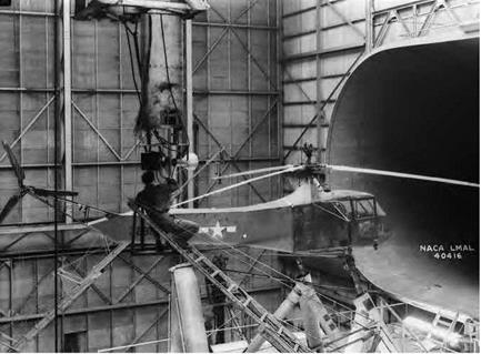
The NACA and NASA have always had a strong interest in promoting Vertical/Short Take-Off and Landing (V/STOL) flight, particularly those sys­tems that make use of rotary wings: helicopters, autogiros, and tilt rotors. New structural materials, advanced propulsion concepts, and the advent of fly-by-wire technology influenced emergent rotary wing technology Work by researchers in various Centers, often in partnership with the military, enabled the United States to achieve dominance in the design and development of advanced military and civilian rotary wing aircraft systems, and continues to address important developments in this field.

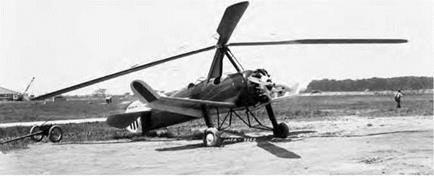
F WORLD WAR I LAUNCHED THE FIXED WING AIRCRAFT INDUSTRY, the Second World War triggered the rotary wing revolution and sowed the seeds of the modern American helicopter industry. The interwar years had witnessed the development of the autogiro, an important short takeoff and landing (STOL) predecessor to the helicopter, but one incapable of true vertical flight, or hovering in flight. The rudimentary helicopter appeared at the end of the interwar era, both in Europe and America. In the United States, the Sikorsky R-4 was the first and only production helicopter used in United States’ military operations during the Second World War. R-4 production started in 1943 as a direct outgrowth of the predecessor, VS-300, the first practical American helicopter, which Igor Sikorsky had refined by the end of 1942. That same year, the American Helicopter Society (AHS) was chartered as a professional engineering society representing the rotary wing industry. Also in 1943, the Civil Aeronautics Administration (CAA), forerunner of the Federal Aviation Administration (FAA), issued Aircraft Engineering Division Report No. 32, "Proposed Rotorcraft Airworthiness.” Thus was America’s rotary wing industry birthed.[268]

NACA-NASA and the Rotary Wing Revolution

Igor Sikorsky flying the experimental VS-300. Sikorsky.

As a result of the industry’s growth spurred by continued military demand during the Korean war and the Vietnam conflict, interest in heli­copters grew almost exponentially. As a result of the boost in demand for helicopters, Sikorsky Aircraft, Bell Helicopter, Piasecki Helicopter (which evolved into Vertol Aircraft Corporation in 1956, becoming the Vertol Division of the Boeing Company in 1960), Kaman Aircraft, Hughes Helicopter, and Hiller Aircraft entered design evaluations and prototype production contracts with the Department of Defense. Over the past 65 years, the rotary wing industry has become a vital sector of the world avia­tion system. Types of private, commercial and military utilization abound using aircraft designs of increasing capability, efficiency, reliability, and safety. Helicopters have now been joined by the military V-22, the first operational tilt rotor, and emerging rotary wing unmanned aerial vehicles (UAV), with both successful rotary wing concepts having potential civil applications. Over the past 78 years, the National Advisory Committee for Aeronautics (NACA) and its successor, the National Aeronautics and Space Administration (NASA), have made significant research and technology contributions to the rotary wing revolution, as evidenced by numerous technical publications on rotary wing research testing, database analysis, and theoretical developments published since the 1930s. These technical

resources have made significant contributions to the Nation’s aircraft industry, military services, and private and commercial enterprises.

Focusing on Fundamentals: The Supersonics Project

In January 2006, NASA Headquarters announced its restructured aeronautics mission. As explained by Associate Administrator for Aeronautics Lisa J. Porter, "NASA is returning to long-term investments

in cutting-edge fundamental research in traditional aeronautical disciplines. . . appropriate to NASA’s unique capabilities.” One of the four new program areas announced was Fundamental Aeronautics (which included supersonic research), with Rich Wlezien as acting director.[524]

During May, NASA released more details on Fundamental Aeronautics, including plans for what was called the Supersonics Project, managed by Mary Jo Long-Davis with Peter Coen as its princi­pal investigator. One of the project’s major technical challenges was to accurately model the propagation of sonic booms from aircraft to the ground incorporating all relevant physical phenomena. These included realistic atmospheric conditions and the effects of vibrations on struc­tures and the people inside (for which most existing research involved military firing ranges and explosives). "The research goal is to model sonic boom impact as perceived both indoors and outdoors.” Developing the propagation models would involve exploitation of existing databases and additional flight tests as necessary to validate the effects of molecular relaxation, rise time, and turbulence on the loudness of sonic booms.[525]

As the Supersonics Project evolved, it added aircraft concepts more challenging than an SSBJ to serve as longer-range targets on which to focus advanced research and technologies. These were a medium-sized (100-200 passenger) Mach 1.6—1.8 supersonic airliner that could have an acceptable sonic boom by about 2020 and an efficient multi-Mach aircraft that might have an acceptably low boom when flying at a speed somewhat below Mach 2 by the years 2030—2035. NASA awarded advanced concept studies for these in October 2008.[526] NASA

also began working with Japan’s Aerospace Exploration Agency (JAXA) on supersonic research, including sonic boom modeling.[527] Although NASA was not ready as yet to develop a new low-boom supersonic research airplane, it supported an application by Gulfstream to the Air Force that reserved the designation X-54A just in case this would be done in the future.[528]

Meanwhile, existing aircraft had continued to prove their value for sonic boom research. During 2005, the Dryden Center began applying a creative new flight technique called low-boom/no-boom to produce controlled booms. Ed Haering used PCBoom4 modeling in developing this concept, which Jim Smolka then refined into a fly- able maneuver with flight tests over an extensive array of pressure sensors and microphones. The new technique allowed F-18s to gen­erate shaped ("low boom”) signatures as well as the evanescent sound waves ("no-boom”) that remain after the refraction and absorption of shock waves generated allow Mach speeds (known as the Mach cutoff) before they reach the surface.

The basic low-boom/no-boom technique requires cruising just below Mach 1 at about 50,000 feet, rolling into an inverted position, diving at a 53-degree angle, keeping the aircraft’s speed at Mach 1.1 during a portion of the dive, and pulling out to recover at about 32,000 feet. This flight profile took advantage of four attributes that contribute to reduced overpressures: a long propagation distance (the relatively high altitude of the dive), the weaker shock waves generated from the top of an aircraft (by diving while upside down), low airframe weight and volume (the relatively small size of an F-18), and a low Mach number. This technique allowed Dryden’s F-18s, which normally generate overpressures of 1.5 psf in level flight, to produce overpressures under 0.1 psf. Using these maneuvers, Dryden’s skilled test pilots could precisely place these focused quiet booms on specific locations, such as those with observers and sensors. Not only were the overpressures low, they had a slower rise time than the typical N-shaped sonic

Focusing on Fundamentals: The Supersonics Project

Focusing on Fundamentals: The Supersonics Project

NASA F-15B No. 836 in flight with Quiet Spike, September 2006. NASA.

signature. The technique also resulted in systematic recordings of evanescent waves—the kind that sound merely like distant thunder.[529]

Dryden researchers used this technique in July 2007 during a test called House Variable Intensity Boom Effect on Structures (House VIBES). Following up on a similar test from the year before with an old (early 1960s) Edwards AFB house slated for demolition,[530] Langley engineers installed 112 sensors (a mix of accelerometers and micro­phones) inside the unoccupied half of a modern (late 1990s) duplex house. Other sensors were placed outside the house and on a nearby 35-foot tower. These measured pressures and vibrations from 12 nor­mal intensity N-shaped booms (up to 2.2 psf) created by F-18s in steady and level flight at Mach 1.25 and 32,000 feet as well as 31 shaped booms (registering only 0.1 to 0.7 psf) from F-18s using the Low Boom/No Boom flight profile. The latter booms were similar to those that would

be expected from an acceptable supersonic business jet. The specially instrumented F-15B No. 852 performed six flights, and an F-18A did one flight. Above the surface boundary layer, an instrumented L-23 sailplane from the Air Force Test Pilot School recorded shock waves at precise locations in the path of the focused booms to account for atmo­spheric effects. The data from the house sensors confirmed fewer vibra­tions and noise levels in the modern house than had been the case with the older house. At the same time, data gathered by the outdoor sen­sors added greatly to NASA’s variable intensity sonic boom database, which was expected to help program and validate sonic boom propa­gation codes for years to come, including more advanced three-dimen­sional versions of PCBoom.[531]

With the awakening of interest in an SSBJ, NASA Langley acoustics specialists including Brenda Sullivan and Kevin Shepherd had resumed an active program of studies and experiments on human and structural response to sonic booms. They upgraded the HSR-era simulator booth with an improved computer-controlled playback system, new loud­speakers, and other equipment to more accurately replicate the sound of various boom signatures, such as those recorded at Edwards. In 2005, they also added predicted boom shapes from several low-boom aircraft designs.[532] At the same time, Gulfstream created a new mobile sonic boom simulator to help demonstrate the difference between traditional and shaped sonic booms to a wider audience. Although Gulfstream’s folded horn design could not reproduce the very low frequencies of Langley’s simulator booth, it created a "traveling” pressure wave that moved past the listener and resonated with postboom noises, features that were judged more realistic than other simulators.

Under the aegis of the Supersonics Project, plans for additional sim­ulation capabilities accelerated. Based on multiple studies that had long cited the more bothersome effects of booms experienced indoors, the

Langley Center began in the summer of 2008 to build one of the most sophisticated sonic boom simulation systems yet. Scheduled for com­pletion in early 2009, it would consist of a carefully constructed 12- by 14-foot room with sound and pressure systems that would replicate all the noises and vibrations caused by various levels and types of sonic booms.[533] Such studies would be vital if most concepts for supersonic business jets were ever to be realized. When the FAA updated its policy on supersonic noise certification in October 2008, it acknowledged the promising results of recent experiments but cautioned that any future changes in the rules against supersonic flight would still depend on public acceptance.[534]

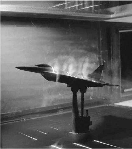
NASA’s Supersonics Project also put a new flight test on its agenda: the Lift and Nozzle Change Effects on Tail Shocks (LaNCETS). Both the SSBD and Quiet Spike experiments had only involved shock waves from the front of an aircraft. Yet shocks from the rear of an aircraft as well as jet engine exhaust plumes also contribute to sonic booms—especially the recompression phase of the typical N-wave signature—but have long been more difficult to control. NASA initiated the LaNCETS experiment to address this issue. As described in the Supersonic Project’s original planning document, one of the metrics for LaNCETS was to "investigate control of aft shock structure using nozzle and/or lift tailoring with the goal of a 20% reduction in near-field tail shock strength.”[535]

NASA Dryden had just the airplane with which to do this: F-15B No. 837. Originally built in 1973 as the Air Force’s first preproduction TF-15A two-seat trainer (soon redesignated as the F-15B), it had been extensively modified for various experiments over its long lifespan. These included the Short Takeoff and Landing Maneuvering Technology Demonstration, the High-Stability Engine Control project, the Advanced Control Technology for Integrated Vehicles Experiment (ACTIVE),

and Intelligent Flight Control Systems (IFCS). F-15B No. 837 had the following special features: digital fly-by-wire controls, canards ahead of the wings for changing longitudinal lift distribution, and thrust-vectoring variable area ratio nozzles on its twin jet engines that could (1) constrict and expand to change the shape the exhaust plumes and (2) change the pitch and yaw of the exhaust flow.[536] It was planned to use these capa­bilities for validating computational tools developed at Langley, Ames, and Dryden to predict the interactions between shocks from the tail and exhaust under various lift and plume conditions.

Tim Moes, one of the Supersonics Project’s associate managers, was the LaNCETS project manager at the Dryden Center. Jim Smolka, who had flown most of F-15B No. 837’s previous missions at Dryden, was its test pilot. He and Nils Larson in F-15B No. 836 conducted Phase I of the test program with three missions from June 17-19, 2008. They gathered baseline measurements with 29 probes, all at 40,000 feet and speeds of Mach 1.2, 1.4, and 1.6.[537]

Several months before Phase II of LaNCETS, NASA specialists and affiliated researchers in the Supersonics Project announced significant progress in near-field simulation tools using the latest in computational fluid dynamics. They even reported having success as far out as 10 body lengths (a mid-field distance). As seven of these researchers claimed in August 2008, "[It] is reasonable to expect the expeditious develop­ment of an efficient sonic boom prediction methodology that will even­tually become compatible with an optimization environment.”[538] Of course, more data from flight-testing would increase the likelihood of this prediction.

LaNCETS Phase II began on November 24, 2008, with nine mis­sions flown by December 11. After being interrupted by a freak snow­storm during the third week of December and then having to break for the holiday season, the LaNCETS team completed the project with flight

tests on January 12, 15, and 30, 2009. In all, Jim Smolka flew 13 mis­sions in F-15B No. 837, 11 of which included in-flight shock wave mea­surements by No. 836 from distances of 100 to 500 feet. Nils Larson piloted the probing flights, with Jason Cudnik or Carrie Rhoades in the back seat. The aircrews tested the effects of both positive and negative canard trim at Mach 1.2, 1.4, and 1.6 as well as thrust vectoring at Mach 1.2 and 1.4. They also gathered supersonic data on plume effects with different nozzle areas and exit pressure ratios. Once again, GPS equip­ment recorded the exact locations of the two aircraft for each of the datasets. On January 30, 2009, with Jim Smolka at the controls for the last time, No. 837 made a final flight before its well-earned retirement.[539]

The large amount of data collected will be made available to indus­try and academia, in addition to NASA researchers at Langley, Ames, and Dryden. For the first time, analysts and engineers will be able to use actual flight test results to validate and improve CFD models on tail shocks and exhaust plumes—taking another step toward the design of a truly low-boom supersonic airplane.[540]

Induced Structural Resonances

Overall, electronic enhancements introduced significant challenges with respect to their practical incorporation in an airplane. Model-following systems required highly responsive servos and high gain levels for the feedback from the motion sensors (gyros and accelerometers) to the con­trol surfaces. These high-feedback-gain requirements introduced serious issues regarding the aircraft structure. An aircraft structure is surpris­ingly vulnerable to induced frequencies, which, like a struck musical tuning fork, can result in resonant motions that may reach the naturally

Induced Structural Resonances

The General Dynamics F-111A was the first production aircraft to use a self-adaptive flight con­trol system. NASA.

destructive frequency of the structure, breaking it apart. Rapid move­ment of a control surface could trigger a lightly damped oscillation of one of the structural modes of the airplane (first mode tail bending, for example). This structural oscillation could be detected by the flight con­trol system sensors, resulting in further rapid movement of the control surface. The resulting structural/control surface oscillation could thus be sustained, or even amplified. These additive vibrations were typically at higher frequencies (5-30 Hz) than the limit-cycle described earlier (2-4 Hz), although some of the landing gear modes and wing bending modes for larger aircraft are typically below 5 Hz. If seemingly esoteric, this phenomenon, called structural resonance, is profoundly serious.

Even the stiff and dense X-15 encountered serious structural reso­nance effects. Ground tests had uncovered a potential resonance between the pitch control system and a landing gear structural mode. Initially, researchers concluded that the effect was related to the ground-test equip­ment and its setup, and thus would not occur in flight. However, after several successful landings, the X-15 did experience a high-frequency vibration upon one touchdown. Additionally, a second and more severe structural resonance occurred at 13 Hz (coincident with the horizon­tal tail bending mode) during one entry from high altitude by the third

X-15 outfitted with the MH-96 adaptive flight control system.[693] The pilot would first note a rumbling vibration that swiftly became louder. As the structure resonated, the vibrations were transmitted to the gyros in the flight control system, which attempted to "correct” for them but actually fed them instead. They were so severe that the pilot could not read the cockpit instruments and had to disengage the pitch damper in order to stop them. As a consequence, a 13 Hz "notch” filter was installed in the electrical feedback path to reduce the gain at the observed structural fre­quency. Thereafter, the third X-15 flew far more predictably[694]

Structural resonance problems are further complicated by the fact that the predicted structural frequencies are often in error, thus the flight control designers cannot accurately anticipate the proper filters for the sensors. Further, structural resonance is related to a structural feedback path, not an aerodynamic one as described for limit-cycles. As a pre­caution, ground vibration tests (GVT) are usually conducted on a new airplane to accurately determine the actual structural mode frequen­cies of the airplane.[695] Researchers attach electrically driven and con­trolled actuators to various locations on the airplane and perform a small amplitude frequency "sweep” of the structure, essentially a "shake test.” Accelerometers at strategic locations on the airplane detect and record the structural response. Though this results in a more accurate determi­nation of the actual structural frequencies for the control system designer, it still does not identify the structural path to the control system sensors.

The flight control resonance characteristics can be duplicated on the ground by placing the airplane on a soft mounting structure, (airbags, or deflated tires and struts) then artificially raising the electrical gain in each flight control closed loop until a vibration is observed. Based on its experience with ground – and flight-testing of research airplanes, NASA DFRC established a ground rule that the flight gains could only be allowed to reach one-half of the gain that triggered a resonance (a gain margin of

2.0). This rule-of-thumb ground rule has been generally accepted within the aircraft industry, and ground tests to establish resonance gain mar­gins are performed prior to first flights. If insufficient gain margin is pres­ent, the solution is sometimes a relocation of a sensor, or a stiffening of the sensor mounting structure. For most cases, the solution is the place­ment of an electronic notch filter within the control loop to reduce the system gain at the identified structural frequency. Many times the fol­lowup ground test identifies a second resonant frequency for a different structural mode that was masked during the first test. A typical notch fil­ter will lower the gain at the selected notch frequency as desired but will also introduce additional lag at nearby frequencies. The additional lag will result in a lowering of the limit-cycle boundaries. The control system designer is thus faced with the task of reducing the gain at one structural frequency while minimizing any increase in the lag characteristics at the limit-cycle frequency (typically 2-4 Hz). This challenge resulted in the cre­ation of lead-lag filters to minimize the additional lag in the system when notch filters were required to avoid structural resonance.[696]

Fighter aircraft usually are designed for 7-9 g load factors and, as a consequence, their structures are quite stiff, exhibiting high natural fre­quencies. Larger transport and reconnaissance airplanes are designed for much lower load factors, and the structures are more limber. Since structural frequencies are often only slightly above the natural aero­dynamic frequencies—as well as the limit-cycle frequencies—of the airplane, this poses a challenge for the flight control system designer who is trying to aggressively control the aerodynamic characteris­tics, avoid limit-cycles, and avoid any control system response at the structural mode frequencies.

Structural mode interactions can occur across a range of flight activ­ities. For example, Rockwell and Air Force testers detected a resonant vibration of the horizontal stabilizer during early taxi tests of the B-1 bomber. It was traced to a landing gear structural mode, and a notch filter was installed to reduce the flight control gain at that frequency. The ground test for resonance is fairly simple, but the structural modes that need to be tested can produce a fairly large matrix of test con­ditions. External stores and fuel loadings can alter the structural fre­quencies of the airplane and thus change the control system feedback

Induced Structural Resonances

Aircraft frequency spectrum for flight control system design. USAF.

characteristics.[697] The frequency of the wing torsion mode of the General Dynamics YF-16 Lightweight Fighter (the prototype of the F-16A Fighting Falcon) was dramatically altered when AIM-9 Sidewinder air-to-air mis­siles were mounted at the wingtip.

The transformed dynamics of the installed missiles induced a seri­ous aileron/wing-twist vibration at 6 Hz (coincident with the wing torsion mode), a motion that could also be classified as flutter, but in this case was obviously driven by the flight control system. Again, the solution was the installation of a notch filter to reduce the aileron response at 6 Hz.[698]

NASA researchers at the Dryden Flight Research Center had an unpleasant encounter with structural mode resonance during the Northrop-NASA HL-10 lifting body flight-test program. After an aborted launch attempt on the HL-10 lifting body, the NB-52B mother ship was returning with the HL-10 still mounted under the wing pylon. When the HL-10 pilot initiated propellant jettison, the launch airplane immedi­ately experienced a violent vibration of the launch pylon attaching the lifting body to the NB-52B. The pilot stopped jettisoning and turned the flight control system off, whereupon the vibration stopped. The solu­tion to this problem was strictly a change in operational procedure—in

the future, the control system was to be disengaged before jettisoning while in captive flight.[699]

Dutch Roll Coupling

Dutch roll coupling is another case of a dynamic loss of control of an airplane because of an unusual combination of lateral-directional static stability characteristics. Dutch roll coupling is a more subtle but nev­ertheless potentially violent motion, one that (again quoting Day) is a "dynamic lateral-directional stability of the stability axis. This coupling of body axis yaw and roll moments with sideslip can produce lateral – directional instability or PIO.”[744] A typical airplane design includes "static directional stability” produced by a vertical fin, and a small amount of "dihedral effect” (roll produced by sideslip). Dihedral effect is created by designing the wing with actual dihedral (wingtips higher than the

wing root), wing sweep (wingtips aft of the wing root), or some combi­nation of the two. Generally static directional stability and normal dihe­dral effect are both stabilizing and both contribute to a stable Dutch roll mode (first named for the lateral-directional motions of smooth-bottom Dutch coastal craft, which tend to roll and yaw in disturbed seas). When the interactive effects of other surfaces of an airplane are introduced, there can be potential regions of the flight envelope where these two contributions to Dutch roll stability are not stabilizing (i. e., regions of negative static directional stability or negative dihedral effect). In these regions, if the negative effect is smaller than the positive influence of the other, then the airplane will exhibit an oscillatory roll-yaw motion. (If both effects are negative, the airplane will show a static divergence in both the roll and yaw axes.) All aircraft that are statically stable exhibit some amount of Dutch roll motion. Most are well damped, and the Dutch roll only becomes apparent in turbulent conditions.

The Douglas DC-3 airliner (equivalent to the military C-47 airlifter) had a persistent Dutch roll that could be discerned by passengers watch­ing the wingtips as they described a slow horizontal "figure eight” with respect to the horizon.

Even the dart-like X-15 manifested Dutch roll characteristics. The very large vertical tail configuration of the X-15 was established by the need to control the airplane near engine burnout if the rocket engine was misaligned, a "lesson learned” from tests of earlier rocket-pow­ered aircraft such as the X-1, X-2, and D-558-2. This led to a large sym­metrical vertical tail with large rudder surfaces both above and below the airplane centerline. (The rocket engine mechanics and engineers at Edwards later devised a method for accurately aligning the engine, so that the large rudder control surfaces were no longer needed.) The X-15 simulator accurately predicted a strange Dutch roll characteristic in the Mach 3-4 region at angles of attack above 8 degrees with the roll and yaw dampers off. This Dutch roll mode was oscillatory and stable with­out pilot inputs but would rapidly diverge into an uncontrollable pilot – induced-oscillation when pilot control inputs were introduced.

During wind tunnel tests after the airplane was constructed, it was discovered that the lower segment of the vertical tail, which was oper­ating in a high compression flow field at hypersonic speeds, was highly effective at reentry angles of attack. The resulting rolling motions pro­duced by the lower fin and rudder were contributing a large negative dihedral effect. Fortunately, this destabilizing influence was not enough

to overpower the high directional stability produced by the very large vertical tail area, so the Dutch roll mode remained oscillatory and stable. The airplane motions associated with this stable oscillation were com­pletely foreign to the test pilots, however. Whereas a normal Dutch roll is described as "like a marble rolling inside a barrel,” NASA test pilot Joe Walker described the X-15 Dutch roll as "like a marble rolling on the out­side of the barrel” because the phase relationship between rolling and yawing were reversed. Normal pilot aileron inputs to maintain the wings level were out of phase and actually drove the oscillation to larger magni­tudes rather quickly. The roll damper, operating at high gain, was fairly effective at damping the oscillation, thus minimizing the pilot’s need to actively control the motion when the roll damper was on.[745]

Because the X-15 roll damper was a single string system (fail-safe), a roll damper failure above about 200,000 feet altitude would have caused the entry to be uncontrollable by the pilot. The X-15 envelope expansion to altitudes above 200,000 feet was delayed until this problem could be resolved. The flight control team proposed installing a backup roll damper, while members of the aerodynamic team proposed removing the lower ventral rudder. Removing the rudder was expected to reduce the direc­tional stability but also would cause the dihedral effect to be stable, thus the overall Dutch roll stability would be more like a normal airplane. The Air Force-NASA team pursued both options. Installation of the backup roll damper allowed the altitude envelope to be expanded to the design value of 250,000 feet. The removal of the lower rudder, however, solved the PIO problem completely, and all subsequent flights, after the initial ventral-off demonstration flights, were conducted without the lower rudder.[746]

The incident described above was unique to the X-15 configura­tion, but the analysis and resolution of the problem is instructive in that it offers a prudent cautioning to designers and engineers to avoid designs that exhibit negative dihedral effect.[747]

Navier-Stokes CFD Solutions

Navier-Stokes CFD SolutionsAs described earlier in this article, the Navier-Stokes equations are the full equations that govern a viscous flow. Solutions of the Navier-Stokes equations are the ultimate in fluid dynamics. To date, no general analyt­ical solutions of these highly nonlinear equations have been obtained. Yet they are the equations that reflect the real world of fluid dynamics. The only way to obtain useful solutions for the Navier-Stokes equations is by means of CFD. And even here such solutions have been slow in coming. The problem has been the very fine grids that are necessary to define certain regions of a viscous flow (in boundary layers, shear layers, separated flows, etc.), thus demanding huge numbers of grid point in the flow field. Practical solutions of the Navier-Stokes equations had to wait for supercomputers such as the Cray X-MP and Cyber 205 to come on the scene. NASA became a recognized and emulated leader in CFD solu­tions of Navier-Stokes equations, its professionalism evident by its hav­ing established the Institute for Computer Applications in Science and Engineering (ICASE) at Langley Research Center, though other Centers as well, particularly Ames, shared this interest in burgeoning CFD. [778] In particular, NASA researcher Robert MacCormack was responsible for the development of a Navier-Stokes CFD code that, by far, became the most popular and most widely used Navier-Stokes CFD algorithm in the last quarter of the 20th century. MacCormack, an applied math­ematician at NASA Ames (and now a professor at Stanford), conceived a straightforward algorithm for the solution of the Navier-Stokes equa­tions, simply identified everywhere as "MacCormack’s method.”

To understand the significance of MacCormack’s method, one must understand the concept of numerical accuracy. Whenever the derivatives in a partial differential equation are replaced by algebraic difference
quotients, there is always a truncation error that introduces a degree of inaccuracy in the numerical calculations. The simplest finite differences, usually involving only two distinct grid points in their formulation, are identified as "first-order” accurate (the least accurate formulation). The next step up, using a more sophisticated finite difference reaching to three grid points, is identified as second-order accurate. For the numer­ical solution of most fluid flow problems, first-order accuracy is not sufficient; not only is the accuracy compromised, but such algorithms frequently blow up on the computer. (The author’s experience, however, has shown that second-order accuracy is usually sufficient for many types of flows.) On the other hand, some of the early second-order algo­rithms required a large computation effort to obtain this second-order accuracy, requiring many pages of paper to write the algorithm and a lot of computations to execute the solution. MacCormack developed a predictor-corrector two-step scheme that was second-order accurate but required much less effort to program and many fewer calculations to execute. He introduced this scheme in an imaginative paper on hyper­velocity impact cratering published in 1969.[779]

Navier-Stokes CFD SolutionsMacCormack’s method broke open the field of Navier-Stokes solu­tions, allowing calculation of myriad viscous flow problems, beginning in the 1970s and continuing to the present time, as was as well (in this author’s opinion) the most "graduate-student friendly” CFD scheme in existence. Many graduate students have cut their CFD teeth on this method and have been able to solve many viscous flow problems that otherwise could not have attempted. Today, MacCormack’s method has been supplanted by several very sophisticated modern CFD algorithms, but even so, MacCormack’s method goes down in history as one of NASA’s finest contributions to the aeronautical sciences.

Goddard Space Flight Center

Goddard Space Flight Center was established in 1959, absorbing the U. S. Navy Vanguard satellite project and, with it, the mission of devel­oping, launching, and tracking unpiloted satellites. Since that time, its roles and responsibilities have expanded to consider space science, Earth observation from space, and unpiloted satellite systems more broadly.

Structural analysis problems studied at Goddard included definition of operating environments and loads applicable to vehicles, subsystems, and payloads; modeling and analysis of complete launch vehicle/payload sys­tems (generic and for specific planned missions); thermally induced loads and deformation; and problems associated with lightweight, deployable structures such as antennas. Control-structural interactions and multi­body dynamics are other related areas of interest.

Goddard’s greatest contribution to computer structural analysis was, of course, the NASTRAN program. With public release of NASTRAN, management responsibility shifted to Langley. However, Goddard remained extremely active in the early application of NASTRAN to practical problems, in the evaluation of NASTRAN, and in the ongoing improvement and addition of new capabilities to NASTRAN: thermal analysis (part of a larger Structural-Thermal-Optical [STOP] program, which is discussed below), hydroelastic analysis, automated cyclic sym­metry, and substructuring techniques, to name a few.[885]

Structural-Thermal-Optical analysis predicts the impact on the per­formance of a (typically satellite-based) sensor system due to the defor­mation of the sensors and their supporting structure(s) under thermal and mechanical loads. After NASTRAN was developed, a major effort began at GSFC to achieve better integration of the thermal and optical analysis components with NASTRAN as the structural analysis compo­nent. The first major product of this effort was the NASTRAN Thermal Analyzer. The program was based on NASTRAN and thereby inherited a great deal of modeling capability and flexibility. But, most impor­tantly, the resulting inputs and outputs were fully compatible with NASTRAN: "Prior to the existence of the NASTRAN Thermal Analyzer, available general purpose thermal analysis computer programs were designed on the basis of the lumped-node thermal balance method.

. . . They were not only limited in capacity but seriously handicapped by incompatibilities arising from the model representations [lumped – node versus finite-element]. The intermodal transfer of temperature data was found to necessitate extensive interpolation and extrapolation. This extra work proved not only a tedious and time-consuming process but also resulted in compromised solution accuracy. To minimize such an interface obstacle, the STOP project undertook the development of a general purpose finite-element heat transfer computer program.”[886] The capability was developed by the MacNeal Schwendler Corporation under subcontract from Bell Aerospace. "It must be stressed, however, that a cooperative financial and technical effort between [Goddard and Langley] made possible the emergence of this capability.”[887]

Another element of the STOP effort was the computation of "view factors” for radiation between elements: "In an in-house STOP proj­ect effort, GSFC has developed an IBM-360 program named ‘VIEW’ which computes the view factors and the required exchange coefficients between radiating boundary elements.”[888] VIEW was based on an ear­lier view factor program, RAVFAC, but was modified principally for compatibility with NASTRAN and eventual incorporation as a subrou­tine in NASTRAN.[889] STOP is still an important part of the analysis of many of the satellite packages that Goddard manages, and work contin­ues toward better performance with complex models, multidisciplinary design, and optimization capability, as well as analysis.