Category AERONAUTICS

Glenn (Formerly Lewis) Research Center

Glenn is the primary Center for research on all aspects of aircraft and spacecraft propulsion, including engine-related structures. The struc­tures area has typically consisted of approximately 50 researchers (not counting materials).[866] Structures research topics include: structures sub­jected to thermal loading, dynamic loading, and cyclic loading; spinning structures; coupled thermo-fluid-structural problems; structures with local plasticity and time-varying properties; probabilistic methods and reliability; analysis of practically every part of a turbine engine; Space Shuttle Main Engine (SSME) components; propeller and propfan flut­ter; failed blade containment analysis; and bird impact analysis. Some of the impact analysis research has been collaborative with Marshall Space Flight Center, which was interested in meteor and space debris impact effects on spacecraft.[867] Glenn has also collaborated extensively with Langley. In 1987, there was a joint Lewis-Langley Workshop on Computational Structural Mechanics (CSM) "to encourage a cooper­ative Langley-Lewis CSM program in which Lewis concentrates on engine structures applications, Langley concentrates on airframe and space structures applications, and all participants share technology of mutual interest.”[868]

Glenn has been involved in NASTRAN improvements since NASTRAN was introduced in 1970 and hosted the sixth NASTRAN Users’ Colloquium. Many of the projects at Glenn built supplemental capabil­ity for NASTRAN to handle the unique problems of propulsion system structural analysis: "The NASA Lewis Research Center has sponsored the development of a number of related analytical/computational capa­bilities for the finite element analysis program, NASTRAN. This devel­opment is based on a unified approach to representing and integrating the structural, aerodynamic, and aeroelastic aspects of the static and dynamic stability and response problems of turbomachines.”[869]

The aircraft and spacecraft engine industries are naturally the pri­mary customers of Glenn technology. However, no attempt is made here to document this technology transfer in detail. Other essays in this vol­ume address advances in propulsion technology and high-temperature materials. Instead, attention is given here to those projects at Glenn that have advanced the general state of the art in computational structures methods and that have found other applications in addition to aero­space propulsion. These include SPAR, NESSUS, SCARE/CARE (and derivatives), ICAN, and MAC.

SPAR was a finite-element structural analysis system developed ini­tially at NASA Lewis in the early 1970s and upgraded extensively through the 1980s. SPAR was less powerful than NASTRAN but relatively inter­active and easy to use for tasks involving iterative design and analysis. Chrysler Corporation used SPAR for designing body panels, starting in the 1980s.[870] NASA Langley has made improvements to SPAR and has used it for many projects, including structural optimization, in conjunc­tion with the Ames CONMIN program.[871] SPAR evolved into the EAL pro­gram, which was used for the structural portion of structural-optical analyses at Marshall.[872] Dryden Flight Research Center has used SPAR for Space Shuttle reentry thermal modeling.

Numerical Evaluation of Stochastic Structures under Stress (NESSUS) was the product of a Probabilistic Structural Analysis Methods (PSAM) project initiated in 1984 for probabilistic structural analysis of Shuttle and future spacecraft propulsion system components. The prime contractor was Southwest Research Institute (SwRI). NESSUS was designed for solving problems in which the loads, boundary con­ditions, and/or the material properties involved are best described by statistical distributions of values, rather than by deterministic (known, single) values. PSAM officially completed in 1995 with the delivery of NESSUS Version 6.2. SwRI was awarded another contract in 2002 for enhancements to NESSUS, leading to the release of Version 8.2 to NASA in December 2004 and commercially in 2005. Los Alamos National Laboratory has used NESSUS for weapon-reliability analysis under its Stockpile Stewardship program. Other applications included auto­motive collision analysis and prediction of the probability of spinal injuries during aircraft ejections, carrier landings, or emergency water landings. NESSUS is used in teaching and research at the University of Texas at San Antonio.[873] In some applications, NESSUS is cou­pled with commercially available deterministic codes offering greater structural analysis capability, with NESSUS providing the statistically derived inputs.[874]

Ceramics Analysis and Reliability Evaluation of Structures (SCARE/ CARES) was introduced as SCARE in 1985 and later renamed CARES. This program performed fast-fracture reliability and failure probability analysis of ceramic components. SCARE was built as a postprocessor to MSC/NASTRAN. Using MSC/NASTRAN output of the stress state in a component, SCARE performed the crack growth and structural reli­ability analysis of the component.[875] Upgrades and a very comprehensive program description and user’s guide were introduced in 1990.[876] In 1993, an extension, CARES/LIFE, was developed to calculate the time depen­dence of the reliability of a component as it is subjected to testing or use. This was accomplished by including the effects of subcritical crack growth over time.[877] Another 1993 upgrade, CCARES (for CMC CARES), added the capability to analyze components made from ceramic matrix composite (CMC) materials, rather than just macroscopically isotropic materials.[878] CARES/PC, introduced in 1994 and made publicly available through COSMIC, ran on a personal computer but offered a more lim­ited capability (it did not include fast-fracture calculations).[879]

R&D Magazine gave an R&D 100 Award jointly to NASA Lewis and to Philips Display Components for application of CARES/Life to the development of an improved television picture tube in 1995. "Cares/ Life has been in high demand world-wide, although present technology transfer efforts are entirely focused on U. S.-based organizations. Success stories can be cited in numerous industrial sectors, including aerospace, automotive, biomedical, electronic, glass, nuclear, and conventional power-generation industries.”[880]

Integrated Composite Analyzer (ICAN) was developed in the early 1980s to perform design and analysis of multilayered fiber composites. ICAN considered hygrothermal (humidity-temperature) conditions as well as mechanical loads and provided results for stresses, stress con­centrations, and locations of probable delamination.[881] ICAN was used extensively for design and analysis of composite space antennas and for analysis of engine components. Upgrades were developed, includ­ing new capabilities and a version that ran on a PC in the early 1990s.[882] ICAN was adapted (as ICAN/PART) to analyze building materials under a cost-sharing agreement with Master Builders, Inc., in 1995.[883]

Goodyear began working with Glenn in 1995 to apply Glenn’s Micromechanics Analysis Code (MAC) to tire design. The relationship was formed, in part, as a result of Glenn’s involvement with the Great Lakes Industrial Technology Center (GLITeC) and the Consortium for the Design and Analysis of Composite Materials. NASA worked with Goodyear to tailor the code to Goodyear’s needs and provided onsite training. MAC was used to assess the effects of chord spacing, ply and belt configurations, and other tire design parameters. By 2002, Goodyear had several tires in production that had benefitted from the MAC design analysis capabilities. Dr. Steven Arnold was the Glenn point of contact in this effort.[884]

TRansfer ANalysis Code to Interface Thermal and Structural (3D TRANCITS, Glenn, 1985)

Transfer of data between different analysis codes has always been one of the challenges of multidisciplinary design, analysis, and optimization. Even if input and output format can be standardized, different types of analysis often require different types of information or different mesh densities, globally or locally. TRANCITS was developed to translate between heat transfer and structural analysis codes: "TRANCITS has the capability to couple finite difference and finite element heat transfer analysis codes to linear and nonlinear finite element structural analysis codes. TRANCITS currently supports the output of SINDA and MARC heat transfer codes directly. It will also format the thermal data out­put directly so that it is compatible with the input requirements of the NASTRAN and MARC structural analysis codes. . . . The transfer mod­ule can handle different elemental mesh densities for the heat transfer analysis and the structural analysis.”[982] MARC is a commercial, general- purpose, nonlinear finite element code introduced by MARC Analysis and Research Corp. in the late 1970s. Because of its nonlinear analysis capabilities, MARC was used extensively at Glenn for engine compo­nent analyses and for other applications, such as the analysis of a space station strongback for launch loads in 1992.[983] Other commercial finite element codes used at Glenn included MSC/NASTRAN, which was used along with NASA’s COSMIC version of NASTRAN.

Turbine Blades

Turbine blades operate at speeds well below hypersonic, but this topic shares the same exotic metals that are used for flight structures at the highest speeds. It is necessary to consider how such blades use coat­ings to stay cool, an issue that represents another form of cooling. It also is necessary to consider directionally solidified and single-crystal castings for blades.

Britain’s firm of Rolls-Royce has traditionally possessed a strong standing in this field, and The Economist has noted its activity:

The best place to start is the surprisingly small, almost under­whelming, turbine blades that make up the heart of the giant engines slung beneath the wings of the world’s biggest planes. These are not the huge fan blades you see when boarding, but are buried deep in the engines. Each turbine blade can fit in the hand like an oversized steak knife. At first glance it may not seem much more difficult to make. Yet they cost about $ 10,000 each. Rolls-Royce’s executives like to point out that their big engines, of almost six tonnes, are worth their weight in silver— and that the average car is worth its weight in hamburger.[1084]

Turbine blades are difficult to make because they have to survive high temperatures and huge stresses. The air inside big jet engines reaches about 2,900 °F in places, 750 degrees hotter than the melting point of the metal from which the turbine blades are made. Each blade is grown from a single crystal of alloy for strength and then coated with tough ceramics. A network of tiny air holes then creates a thin blanket of cool air that stops it from melting.

The study of turbine blades brings in the topic of thermal barrier coatings (TBC). By attaching an adherent layer of a material of low ther­mal conductivity to the surface of an internally cooled turbine blade, a temperature drop is induced across the thickness of the layer. This results in a drop in the temperature of the metal blade. Using this approach, temperature reductions of up to 340 °F at the metal surface have been estimated for 150-micron-thick yttria stabilized zirconia coatings. The rest of the temperature decrease is obtained by cooling the blade using air from the compressor that is ducted downstream to the turbine.

The cited temperature reductions reduce the oxidation rate of the bond coat applied to the blades and so delay failure by oxidation. They also retard the onset of thermal fatigue. One should note that such coat­ings are currently used only to extend the life of components. They are not used to increase the operating temperature of the engine.

Modern TBCs are required to not only limit heat transfer through the coating but to also protect engine components from oxidation and hot corrosion. No single coating composition appears able to satisfy these requirements. As a result, a "coating system” has evolved. Research in the last 20 years has led to a preferred coating system consisting of four separate layers to achieve long-term effectiveness in the high-tem­perature, oxidative, and corrosive environment in which the blades must function. At the bottom is the substrate, a nickel – or cobalt-based super­alloy that is cooled from the inside using compressor air. Overlaying it is the bond coat, an oxidation-resistant layer with thickness of 75-150 microns that is typically of a NiCrAlY or NiCoCrAlY alloy. It essentially dictates the spallation failure of the blade. Though it resists oxidation, it does not avoid it; oxidation of this coating forms a third layer, the ther­mally grown oxide, with a thickness of 1 to 10 microns. It forms as Al2O3. The topmost layer, the ceramic topcoat, provides thermal insulation. It is typically of yttria-stabilized ZrO2. Its thickness is characteristically about 300 microns when deposited by air plasma spray and 125 microns when deposited by electron beam physical vapor deposition (EB-PVD).[1085]

Yttria-stabilized zirconia has become the preferred TBC layer mate­rial for use in jet engines because of its low thermal conductivity and its relatively high thermal expansion coefficient, compared with many other ceramics. This reduces the thermal expansion mismatch with the met­als of high thermal expansion coefficient to which it is applied. It also has good erosion resistance, which is important because of the entrain­ment of particles having high velocity in the engine gases. Robert Miller, a leading specialist, notes that NASA and the NACA, its predecessor, have played a leading role in TBC development since 1942. Flame-sprayed Rokide coatings, which extended the life of the X-15 main engine com­bustion chamber, represented an early success. Magnesia-stabilized zir­conia later found use aboard the SR-71, allowing continuous use of the afterburner and sustained flight above Mach 3. By 1970, plasma-sprayed TBCs were in use in commercial combustors.[1086]

These applications involved components that had no moving parts. For turbines, the mid-1970s brought the first "modern” thermal spray coating. It used yttria as a zirconia stabilizer and a bond coat that contained MCrAlY, and demonstrated that blade TBCs were feasible.

C. W. Goward of Pratt & Whitney (P&W), writing of TBC experience with the firm’s J7 5 engine, noted: "Although the engine was run at rel­atively low pressures, the gas turbine engine community was sufficiently impressed to prompt an explosive increase in development funds and programs to attempt to achieve practical utilization of the coatings on turbine airfoils.”[1087]

But tests in 1977 on the more advanced JT9D, also conducted at P&W, brought more mixed results. The early TBC remained intact on lower-temperature regions of the blade but spalled at high tempera­tures. This meant that further development was required. Stefan Stecura reported an optimum concentration of Y2O3 in ZrO2 of 6-8 percent. This is still the state of the art. H. G. Scott reported that the optimum phase of zirconia was t’-ZrO2. In 1987, Stecura showed that ytterbia – stabilized zirconia on a ytterbium-containing bond coat doubled the blade life and took it from 300 1-hour cycles to 600 cycles. Also at that time, P&W used a zirconia-yttria TBC to address a problem with endur­ance of vane platforms. A metallic platform, with no thermal barrier, showed burn-through and cracking from thermal-mechanical fatigue after 1,500 test cycles. Use of a TBC extended the service life to 18,000 hours or 2,778 test cycles and left platforms that were clean, uncracked, and unburned. P&W shared these results with NASA, which led to the TBC task in the Hot Section Technology (HOST) program. NASA col­laborated with P&W and four other firms as it set out to predict TBC lifetimes. A preliminary NASA model showed good agreement between experiment and calculation. P&W identified major degradation modes and gave data that also showed good correlation between measured and modeled lives. Other important contributions came from Garrett Turbine Co. and General Electric. The late 1980s brought Prescribed Velocity Distribution (PVD) blades that showed failure when they were nearly out of the manufacturer’s box. EV-PVD blades resolved this issue and first entered service in 1989 on South African Airways 747s. They flew from Johannesburg, a high-altitude airport with high mean tem­peratures where an airliner needed a heavy fuel load to reach London. EV-PVD TBCs remain the coating of choice for first-row blades, which see the hottest combustion gases. TBC research continues to this day, both at NASA and its contractors. Fundamental studies in aeronautics are important, with emphasis on erosion of turbine components. This work has been oriented toward rotorcraft and has brought the first EV-PVD coating for their blades. There also has been an emphasis on damping of vibration amplitudes. A new effort has dealt with environ­mental barrier coatings (EBCs), which Miller describes as "ceramic coatings, such as SiC, on top of ceramics.”[1088]

Important collaborations have included work on coatings for die­sels, where thick TBCs permit higher operating temperatures that yield increased fuel economy and cleaner exhaust. This work has proceeded with Caterpillar Tractor Co. and the Army Research Laboratory.[1089]

Studies of supersonic engines have involved cooperation with P&W and GE, an industrial interaction that Miller described as "a useful reality check.”[1090] NASA has also pursued the Ultra Efficient Engine Technology program. Miller stated that it has not yet introduced engines for routine service but has led to experimental versions. This work has involved EBCs, as well as a search for low thermal conductivity. The latter can increase engine-operating temperatures and reduce cooling requirements, thereby achieving higher engine efficiency and lower emissions. At NASA Glenn, Miller and Dong-ming Zhu have built a test facility that uses a 3-kilowatt CO2 laser with wavelength of 10.6 microns. They also have complemented conventional ZrO2- Y2O3 coatings with other rare-earth oxides, including Nd2O3-Yb2O3 and Gd2O3-Yb2O3.[1091]

Can this be reduced further? A promising approach involves devel­opment of new deposition techniques that give better control of TBC pore morphology. Air plasma spray deposition creates many intersplat pores between initially molten droplets, in what Miller described as "a messy stack of pancakes.” By contrast, TBC layers produced by EB-PVD have a columnar microstructure with elongated intercolumnar pores that align perpendicular to the plane of the coating. Alternate depo­sition methods include sputtering, chemical vapor deposition (CVD), and sol-gel approaches. But these approaches involve low deposition rates that are unsuitable for economic production of coated blades. CVD and sol-gel techniques also require the use of dangerous and costly precursor materials. In addition, none of these approaches permit the precise control and manipulation of pore morphology. Thus, improved deposition methods that control this morphology do not now exist.

DFBW F-8: Phase II

On November 16, 1973, the DFBW team received a NASA group achieve­ment award for its highly impressive accomplishments during the Phase I effort. By that time, planning was well underway for the Phase II effort, with the first version of the software specification having already been issued in April 1973. Whereas Phase I had verified the feasibility of flight control using a digital computer, Phase II was intended to develop a more practical approach to the implementation of digital flight control, one that could be used to justify the incorporation of digital technology into production designs for both military and commercial use. In the Phase

II design, the single channel Apollo computer-based flight control sys­tem was replaced with a triply redundant flight control system approach using three International Business Machines (IBM) AP-101 digital com­puters. The challenge was how to program this multicomputer system to act as a single computer in processing flight control laws and directing aircraft maneuvers while functioning independently for purposes of fault tolerance.[1160] The 32-bit IBM AP-101 computer had been selected for use in the Space Shuttle. It consumed 370 watts of power, weighed about 50 pounds, and had 32,000 words of memory.[1161] The DFBW program decided to also use the AP-101 computer in its Phase II effort, and a purchase contact with IBM was signed in August 1973. However, the reliability of the AP-101 computer, as measured by mean time between failures, left much to be desired. The computer would turn out to require major rede­sign, and it never came close to meeting its reliability projections. As Ken Szalai recently commented: "the IBM AP-101 computer was one of the last of the ‘beasts.’ It was big and ran hot. The circuit boards tended to fail as temperatures increased. This was found to be due to thermal expan­sion causing the layers within the circuit boards to separate breaking their electrical connections.” Szalai recounted that he notified the Space Shuttle team as soon as the issue was discovered. They were surprised, as they had never seen a similar problem with the AP-101. The reason soon became apparent. The AP-101s installed in the F-8 Iron Bird were being tested in a non-air-conditioned hangar; Space Shuttle flight control sys­tem testing had been in a 50 degree Fahrenheit (50 °F) cooled laboratory environment. When the Space Shuttle was tested on the flight line in typ­ical outside temperatures encountered at Dryden, similar reliability prob­lems were encountered. IBM subsequently changed the thermal coating process used in the manufacture of the AP-101 circuit boards, a measure that partly resolved the AP-101’s reliability problems.[1162]

Подпись: 10Software for Phase II was also larger and more complex than that used in Phase I because of the need for new pilot interface devices. Flight control modes still included the direct (DIR) mode, the stability aug­mentation (SAS) mode, and the control-augmentation (CAS) mode. A pitch maneuver-load-control feature was added to the CAS mode, and a digital autopilot was fitted that incorporated Mach hold, altitude-hold,

and heading-hold selections. The software gradually matured to the point where pilots could begin verification evaluations in the Iron Bird sim­ulator in early 1976. By July, no anomalies were reported in the latest software release, with the direct and stability-augmentation modes con­sidered flight-ready. The autopilot and control-augmentation mode still required more development, but they were not necessary for first flight.

Подпись: 10The backup analog flight control system was also redesigned for Phase II, and the secondary actuators were upgraded. Sperry supplied an updated version of the Phase I Backup Control System using the same technology that had been used in the Air Force’s YF-4E project. Signals from the analog computers were now force-summed when they reached the actuators, resulting in a quicker response. The redesigned secondary actuators provided 20 percent more force, and they were also more reli­able. The hydraulic actuators used in Phase I had two sources of hydraulic pressure for the actuators; in those chosen for Phase II, there were three hydraulic sources that corresponded with the three channels in each of the primary and secondary flight control systems. The secondary elec­tronic actuators had three channels, with one dedicated to each computer in the primary system. The actuators were shared by the analog com­puter bypass system in the event of failure of the primary digital system.

The final Phase II design review occurred in late May 1975, with both the Iron Bird and aircraft 802 undergoing modification well into 1976. By early April, Gary Krier was able to fly the Iron Bird simulator with flight hardware and software. Handling qualities were generally rated as very good, but actuator anomalies and transients were noted, as were some problems with the latest software releases. After these issues were resolved, a flight qualification review was completed on August 20. High-speed taxi tests beginning 3 days later, then, on August 27, 1976, Gary Krier took off on the first flight of the Phase II program. On the second Phase II flight, one of the AP-101 computers failed with the aircraft at supersonic speed. An uneventful landing was accomplished with the flight control system remaining in the primary flight control mode. This was in accordance with the established flight-test procedure in the event of a failure of one of the primary computers. Flight-testing was halted, and all AP-101s were sent back to IBM for refurbishment. After 4 months, the AP-101s were back at Dryden, but another AP-101 computer failure occurred on the very next flight. Again, the primary digital flight control system handled the failure well, and flights were soon being accomplished without inci­dent, providing ever increasing confidence in the system.

In the spring of 1977, the DFBW F-8 was modified to support the Space Shuttle program. It flew eight times with the Shuttle Backup Flight System’s software test package running in parallel with the F-8 flight control software. Data from this package were downlinked as the F-8 pilots flew a series of simulated Shuttle landing profiles. Later in 1977, the unpowered Space Shuttle Enterprise was being used to evaluate the flight characteristics of the Space Shuttle during approach and landing in preparation for full-up shuttle missions. During the Shuttle Approach and Landing Test (ALT) program, the Enterprise was carried aloft atop the NASA 747 Shuttle carrier aircraft. After release, the Shuttle’s han­dling qualities and the responsiveness of its digital fly-by-wire system were evaluated. On the fifth and last of the shuttle ALT flights in October 1977, a pilot-induced oscillation developed just as the Enterprise was landing. The DFBW F-8C was then used in a project oriented to dupli­cating the PIO problem encountered on the Shuttle during a series of flights in 1978 that were initially flown by Krier and McMurtry. They were joined by Einar K. Enevoldson and John A. Manke, who had exten­sive experience flying NASA lifting body vehicles. The lifting body vehi­cles used side stick controllers and had approach characteristics that were similar to those of the Space Shuttle.

Подпись: 10Flying simulated Shuttle landing profiles with the DFBW F-8, the pilots gathered extremely valuable data that supported the Shuttle pro­gram in establishing sampling rates and control law execution limits. The DFBW F-8 flight control software had been modified to enable the pilot to vary transport delay times to evaluate their effect on control response. Transport delay is the elapsed time between pilot movement of his cockpit control and the actual movement of the flight control sur­faces. It is a function of several factors, including the time needed to do analog-to-digital conversion, the time required to execute the appropri­ate flight control law, length of the electrical wires to the actuators, and the lag in response of the hydraulic system. If transport delay is too long, the pilot may direct additional control surface movement while his ini­tial commands are in the process of being executed by the flight control system. This can result in overcontrol. Subsequent attempts to correct the overshoot can lead to a series of alternating overshoots or oscilla­tions that are commonly referred to as a PIO. The range of transport delay times within which the Shuttle would be unlikely to encounter a PIO was determined using the DFBW F-8, enabling Dryden to develop a PIO suppression filter for the Shuttle. The PIO suppression filter was

successfully evaluated in the F-8, installed in the Shuttle prior to its first mission into space, and proved to effectively eliminate the PIO issue.[1163]

Подпись: 10During Phase II, 169 flights were accomplished with several other test pilots joining the program, including Stephen D. Ishmael, Rogers Smith, and Edward Schneider. In addition to its previously noted accom­plishments, the DFBW F-8 successfully evaluated adaptive control law approaches that would later become standard in many FBW aircraft. It was used in the Optimum Trajectory Research Experiment (OPTRE). This involved testing data uplink and downlink between the F-8 and a computer in the then-new Remotely Piloted Vehicle Facility. This exper­iment demonstrated that an aircraft equipped with a digital flight con­trol system could be flown using control laws that were operating in ground-based digital computers. The F-8 conducted the first in-flight eval­uations of an automatic angle-of-attack limiter and maneuvering flaps. These features are now commonly used on nearly all military and com­mercial aircraft with fly-by-wire flight controls. The DFBW F-8 also suc­cessfully tested an approach that used a backup software system known as the Resident Backup System (REBUS) to survive potential software faults that could cause all three primary flight control system comput­ers to fail. The REBUS concept was later used in other experimental aircraft, as well as in production fly-by-wire flight control systems. The final flight-test effort of the DFBW program involved the development of a methodology called analytical redundancy management. In this concept, dynamic and kinematic relationships between dissimilar sen­sors and measurements were used to detect and isolate sensor failures.[1164]

U. K. Jaguar ACT

In the U. K., the Royal Aircraft Establishment began an effort ori­ented to producing a CCV testbed in 1977. For this purpose, an Anglo – French Jaguar strike fighter was modified by British Aerospace (BAe) to prove the feasibility of active control technology. Known as the Jaguar Active Control Technology (ACT), the aircraft’s mechanical flight control system was entirely removed and replaced with a quad-redundant digital fly-by-wire control system that used electrical channels to relay instructions to the flight control surfaces. The initial flight of the Jaguar ACT with the digital FBW system was in October 1981. As with the CCV F-104G, ballast was added to the aft fuselage to move the center of gravity aft and destabilize the aircraft. In 1984, the Jaguar ACT was fitted with rounded oversized leading-edge strakes to move the center of lift of the aircraft forward, further contributing to pitch instability. It first flew in this configuration in March 1984. Marconi developed the Jaguar ACT flight control system. It included an optically coupled data transmission link that was essentially similar to the one that they had developed for the U. S. Air Force YC-14 program (an interesting example of the rapid proliferation of advanced aerspace technology between nations).[1218]

Flight-testing began in 1981, with the test program ending in 1984 after 96 flights.[1219]

Advancing Propulsive Technology

James Banke

Подпись: ПEnsuring proper aircraft propulsion has been a powerful stimulus. In the interwar years, the NACA researched propellers, fuels, engine cool­ing, supercharging, and nacelle and cowling design. In the postwar years, the Agency refined gas turbine propulsion technology. NASA now leads research in advancing environmentally friendly and fuel-con­serving propulsion, thanks to the Agency’s strengths in aerodynamic and thermodynamic analysis, composite structures, and other areas.

E

ACH DAY, OUR SKIES FILL with general aviation aircraft, business jets, and commercial airliners. Every 24 hours, some 2 million passen­gers worldwide are moved from one airport to the next, almost all of them propelled by relatively quiet, fuel-efficient, and safe jet engines.[1291]

And no matter if the driving force moving these vehicles through the air comes from piston-driven propellers, turboprops, turbojets, turbofans— even rocket engines or scramjets—the National Aeronautics and Space Administration (NASA) during the past 50 years has played a significant role in advancing that propulsion technology the public counts on every day.

Many of the advances seen in today’s aircraft power-plants can trace their origins to NASA programs that began during the 1960s, when the Agency responded to public demand that the Government apply major resources to tackling the problems of noise pollution near major airports. Highlights of some of the more noteworthy research programs to reduce noise and other pollution, prolong engine life, and increase fuel efficiency will be described in this case study.

But efforts to improve engine efficiency and curb unwanted noise actu­ally predate NASA’s origins in 1958, when its predecessor, the National Advisory Committee for Aeronautics (NACA), served as the Nation’s pre­eminent laboratory for aviation research. It was during the 1920s that

Подпись: 11 Advancing Propulsive Technology

the NACA invented a cowling to surround the front of an airplane and its radial engine, smoothing the aerodynamic flow around the aircraft while also helping to keep the engine cool. In 1929, the NACA won its first Collier Trophy for the breakthrough in engine and aerodynamic technology.[1292]

During World War II, the NACA produced new ways to fix problems discovered in higher-powered piston engines being mass-produced for wartime bombers. NACA research into centrifugal superchargers was particularly useful, especially on the R-1820 Cyclone engines intended for use on the Boeing B-17 Flying Fortress, and later with the Wright R-3350 Duplex Cyclone engines that powered the B-29.

Basic research on aircraft engine noise was conducted by NACA engineers, who reported their findings in a paper presented in 1956 to the 51st Meeting of the Acoustical Society of America in Cambridge, MA. It would seem that measurements backed up the prediction that the noise level of the spinning propeller depended on several variables,
including the propeller diameter, how fast it is turning, and how far away the recording device is from the engine.[1293]

Подпись: 11As the jet engine made its way from Europe to the United States and designs for the basic turboprop, turbojet, and turbofan were refined, the NACA during the early 1950s began one of the earliest noise-reduction programs, installing multitube nozzles of increasing complexity at the back of the engines to, in effect, act as mufflers. These engines were tested in a wind tunnel at Langley Research Center in Hampton, VA. But the effort was not effective enough to prevent a growing public sentiment that commercial jet airliners should be seen and not heard.

In fact, a 1952 Presidential commission chaired by the legendary pilot James H. Doolittle predicted that aircraft noise would soon turn into a problem for airport managers and planners. The NACA’s response was to form a Special Subcommittee on Aircraft Noise and pursue a three – part program to understand better what makes a jet noisy, how to quiet it, and what, if any, impact the noise might have on the aircraft’s structure.[1294]

As the NACA on September 30, 1958, turned overnight into the National Aeronautics and Space Administration on October 1, the new space agency soon found itself with more work to do than just beating the Soviet Union to the Moon.

Advanced Subsonic Technology Program and UEET

Подпись: 12NASA started a project in the mid-1990s known as the Advanced Subsonic Technology program. Like HSR before it, the AST focused heavily on reducing emissions through new combustor technology. The overall objective of the AST was to spur technology innovation to ensure U. S. leadership in developing civil transport aircraft. That meant lowering NOx emissions, which not only raised concern in local airport com­munities but also by this time had become a global concern because of potential damage to the ozone layer. The AST sought to spur the devel­opment of new low-emissions combustors that could achieve at least a 50-percent reduction in NOx from 1996 International Civil Aviation Organization standards. The AST program also sought to develop tech­niques that would better measure how NOx impacts the environment.[1417]

GE, P&W, Allison Engines, and AlliedSignal engines all participated in the project.[1418] Once again, the challenge for these companies was to con­trol combustion in such a way that it would minimize emissions. This required carefully managing the way fuel and air mix inside the combustor to avoid extremely hot temperatures at which NOx would be created, or at least reducing the length of time that the gases are at their hottest point.

Ultimately the AST emissions reduction project achieved its goal of reducing NOx emissions by more than 50 percent over the ICAO stan­dard, a feat that was accomplished not with actual engine demonstrators but with a "piloted airblast fuel preparation chamber.”[1419]

Подпись: 12Despite their relative success, however, NASA’s efforts to improve engine efficiency and reduce emissions began to face budget cuts in 2000. Funding for NASA’s Atmospheric Effects of Aviation project, which was the only Government program to assess the effects of aircraft emissions at cruise altitudes on climate change, was canceled in 2000.[1420] Investments in the AST and the HSR also came to an end. However, NASA did manage to salvage parts of the AST aimed at reducing emissions by rolling those projects into the new Ultra Efficient Engine Technology program in 2000.[1421]

UEET was a 6-year, nearly $300 million program managed by NASA Glenn that began in October 1999 and included participation from NASA Centers Ames, Goddard, and Langley; engine companies GE Aircraft Engines, Pratt & Whitney, Honeywell, Allison/Rolls Royce, and Williams International; and airplane manufacturers Boeing and Lockheed Martin.[1422]

UEET sought to develop new engine technologies that would dramat­ically increase turbine performance and efficiency. It sought to reduce NOx emissions by 70 percent within 10 years and 80 percent within 25 years, using the 1996 International Civil Aviation Organization guidelines as a baseline.[1423] The UEET project also sought to reduce carbon dioxide emissions by 20 percent and 50 percent in the same timeframes, using 1997 subsonic aircraft technology as a baseline.[1424] The dual goals posed a major challenge because current aircraft engine technologies typically require a tradeoff between NOx and carbon emissions; when engines are designed to minimize carbon dioxide emissions, they tend to generate more NOx.

In the case of the UEET project, improving fuel efficiency was expected to lead to a reduction in carbon dioxide emissions by at least
8 percent: the less fuel burned, the less carbon dioxide released.[1425] The UEET program was expected to maximize fuel efficiency, requiring engine operations at pressure ratios as high as 55 to 1 and turbine inlet tem­peratures of 3,100 degrees Fahrenheit (°F).[1426] However, highly efficient engines tend to run at very hot temperatures, which lead to the genera­tion of more NOx. Therefore, in order to reduce NOx, the UEET program also sought to develop new fuel/air mixing processes and separate engine component technologies that would reduce NOx emissions 70 percent from 1996 ICAO standards for takeoff and landing conditions and also minimize NOx impact during cruise to avoid harming Earth’s ozone layer.

Подпись: 12Under UEET, NASA worked on ceramic matrix composite (CMC) combustor liners and other engine parts that can withstand the high temperatures required to maximize energy efficiency and reduce car­bon emissions while also lowering NOx emissions. These engine parts, particularly combustor liners, would need to endure the high temper­atures at which engines operate most efficiently without the benefit of cooling air. Cooling air, which is normally used to cool the hottest parts of an engine, is unacceptable in an engine designed to minimize NOx, because it would create stoichiometric fuel-air mixtures—meaning the number of fuel and air molecules would be optimized so the gases would be at their hottest point—thereby producing high levels of NOx in regions close to the combustor liner.[1427]

NASA’s sponsorship of the AST and the UEET also fed into the devel­opment of two game-changing combustor concepts that can lead to a significant reduction in NOx emissions. These are the Lean Pre-mixed, Pre-vaporized (LPP) and Rich, Quick Mix, Lean (RQL) combustor con­cepts. P&W and GE have since adopted these concepts to develop com­bustors for their own engine product lines. Both concepts focus on improving the way fuel and air mix inside the engine to ensure that core temperatures do not get so high that they produce NOx emissions.

GE has drawn from the LPP combustor concept to develop its Twin Annular Pre-mixing Swirler (TAPS) combustor. Under the LPP concept,
air from the high-pressure compressor comes into the combustor through two swirlers adjacent to the fuel nozzles. The swirlers premix the fuel and combustion air upstream from the combustion zone, creating a lean (more air than fuel) homogenous mixture that can combust inside the engine without reaching the hottest temperatures, at which NOx is created.[1428]

Подпись: 12NASA support also helped lay the groundwork for P&W’s Technology for Advanced Low Nitrogen Oxide (TALON) low-emissions combustor, which reduces NOx emissions through the RQL process. The front end of the combustor burns very rich (more fuel than air), a process that suppresses the formation of NOx. The combustor then transitions in milliseconds to burning lean. The air must mix very rapidly with the combustion products from the rich first stage to prevent NOx forma­tion as the rich gases are diluted.[1429] The goal is to spend almost no time at extremely hot temperatures, at which air and fuel particles are evenly matched, because this produces NOx.[1430]

Today, NASA continues to study the difficult problem of increas­ing fuel efficiency and reducing NOx, carbon dioxide, and other emis­sions. At NASA Glenn, researchers are using an Advanced Subsonic Combustion Rig (ASCR), which simulates gas turbine combustion, to engage in ongoing emissions testing. P&W, GE, Rolls Royce, and United Technologies Corporation are continuing contracts with NASA to work on low-emissions combustor concepts.

"The [ICAO] regulations for NOx keep getting more stringent,” said Dan Bulzan, NASA’s associate principle investigator for the sub­sonic fixed wing and supersonic aeronautics project. "You can’t just sit there with your old combustor and expect to meet the NOx emissions regulations. The Europeans are quite aggressive and active in this area as well. There is a competition on who can produce the lowest emissions combustor.”[1431]

Solar Propulsion for High-Altitude Long-Endurance Unmanned Aerial Vehicles

Подпись: 13Another area of NASA involvement in the development and use of alter­native energy was work on solar propulsion for High-Altitude Long – Endurance (HALE) unmanned aerial vehicles (remotely piloted vehicles). Work in this area evolved out of the Agency’s Environmental Research Aircraft and Sensor Technology (ERAST) program that started in 1994. This program, which was a joint NASA/industry effort through a Joint Sponsored Research Agreement (JSRA), was under the direction of NASA’s Dryden Flight Research Center. The primary objectives of the ERAST program were to develop and transfer advanced technology to an emerging American unmanned aerial vehicle industry, and to con­duct flight demonstrations of the new technologies in controlled envi­ronments to validate the capability of UAVs to undertake operational science missions. A related and important aspect of this mission was the development, miniaturization, and integration of special purpose sen­sors and imaging equipment for the solar-powered aircraft. These goals were in line with both the revolutionary vehicles development aspect of NASA’s Office of Aerospace Technology aeronautics blueprint and with NASA’s Earth Science Enterprise efforts to expand scientific knowledge of the Earth system using NASA’s unique capabilities from the stand­point of space, aircraft, and onsite platforms.[1519]

Specific program objectives were to develop UAV capabilities for flying at extremely high altitudes and for long periods of time; demon­strate payload capabilities and sensors for atmospheric research; address and resolve UAV certification and operational issues; demonstrate the UAV’s usefulness to scientific, Government, and civil customers; and foster the emergence of a robust UAV industry in the United States.[1520]

The ERAST program envisioned missions that included remote sensing for Earth science studies, hyperspectral imaging for agriculture monitoring, tracking of severe storms, and serving as telecommunica­tions relay platforms. Related missions called for the development and testing of lightweight microminiaturized sensors, lightweight materi­als, avionics, aerodynamics, and other forms of propulsion suitable for extreme altitudes and flight duration.[1521]

Подпись: 13The ERAST program involved the development and testing of four generations of solar-powered UAVs, including the Pathfinder, the Pathfinder Plus, the Centurion, and the Helios Prototype. Because of budget limitations, the Helios Prototype was reconfigured in what could be considered a fifth-generation test vehicle for long-endurance flying (see below). Earlier UAVs, such as the Perseus, Theseus, and Proteus, relied on gasoline-powered engines. The first solar-powered UAV was the RAPTOR/Pathfinder, also known as the High-Altitude Solar (HALSOL) aircraft, which that was originally developed by the U. S. Ballistic Missile Defense Organization (BMDO—now the Missile Defense Agency) as part of a classified Government project and subsequently turned over to NASA for the ERAST program. In addition to BMDO’s interest in having NASA take over solar vehicle development, a workshop held in Truckee, CA, in 1989 played an important role in the origin of the ERAST program.

NACA-NASA and the Rotary Wing Revolution

John F. Ward

The NACA and NASA have always had a strong interest in promoting Vertical/Short Take-Off and Landing (V/STOL) flight, particularly those sys­tems that make use of rotary wings: helicopters, autogiros, and tilt rotors. New structural materials, advanced propulsion concepts, and the advent of fly-by-wire technology influenced emergent rotary wing technology Work by researchers in various Centers, often in partnership with the military, enabled the United States to achieve dominance in the design and development of advanced military and civilian rotary wing aircraft systems, and continues to address important developments in this field.

F WORLD WAR I LAUNCHED THE FIXED WING AIRCRAFT INDUSTRY, the Second World War triggered the rotary wing revolution and sowed the seeds of the modern American helicopter industry. The interwar years had witnessed the development of the autogiro, an important short takeoff and landing (STOL) predecessor to the helicopter, but one incapable of true vertical flight, or hovering in flight. The rudimentary helicopter appeared at the end of the interwar era, both in Europe and America. In the United States, the Sikorsky R-4 was the first and only production helicopter used in United States’ military operations during the Second World War. R-4 production started in 1943 as a direct outgrowth of the predecessor, VS-300, the first practical American helicopter, which Igor Sikorsky had refined by the end of 1942. That same year, the American Helicopter Society (AHS) was chartered as a professional engineering society representing the rotary wing industry. Also in 1943, the Civil Aeronautics Administration (CAA), forerunner of the Federal Aviation Administration (FAA), issued Aircraft Engineering Division Report No. 32, "Proposed Rotorcraft Airworthiness.” Thus was America’s rotary wing industry birthed.[268]

NACA-NASA and the Rotary Wing Revolution

Igor Sikorsky flying the experimental VS-300. Sikorsky.

As a result of the industry’s growth spurred by continued military demand during the Korean war and the Vietnam conflict, interest in heli­copters grew almost exponentially. As a result of the boost in demand for helicopters, Sikorsky Aircraft, Bell Helicopter, Piasecki Helicopter (which evolved into Vertol Aircraft Corporation in 1956, becoming the Vertol Division of the Boeing Company in 1960), Kaman Aircraft, Hughes Helicopter, and Hiller Aircraft entered design evaluations and prototype production contracts with the Department of Defense. Over the past 65 years, the rotary wing industry has become a vital sector of the world avia­tion system. Types of private, commercial and military utilization abound using aircraft designs of increasing capability, efficiency, reliability, and safety. Helicopters have now been joined by the military V-22, the first operational tilt rotor, and emerging rotary wing unmanned aerial vehicles (UAV), with both successful rotary wing concepts having potential civil applications. Over the past 78 years, the National Advisory Committee for Aeronautics (NACA) and its successor, the National Aeronautics and Space Administration (NASA), have made significant research and technology contributions to the rotary wing revolution, as evidenced by numerous technical publications on rotary wing research testing, database analysis, and theoretical developments published since the 1930s. These technical

resources have made significant contributions to the Nation’s aircraft industry, military services, and private and commercial enterprises.

Focusing on Fundamentals: The Supersonics Project

In January 2006, NASA Headquarters announced its restructured aeronautics mission. As explained by Associate Administrator for Aeronautics Lisa J. Porter, "NASA is returning to long-term investments

in cutting-edge fundamental research in traditional aeronautical disciplines. . . appropriate to NASA’s unique capabilities.” One of the four new program areas announced was Fundamental Aeronautics (which included supersonic research), with Rich Wlezien as acting director.[524]

During May, NASA released more details on Fundamental Aeronautics, including plans for what was called the Supersonics Project, managed by Mary Jo Long-Davis with Peter Coen as its princi­pal investigator. One of the project’s major technical challenges was to accurately model the propagation of sonic booms from aircraft to the ground incorporating all relevant physical phenomena. These included realistic atmospheric conditions and the effects of vibrations on struc­tures and the people inside (for which most existing research involved military firing ranges and explosives). "The research goal is to model sonic boom impact as perceived both indoors and outdoors.” Developing the propagation models would involve exploitation of existing databases and additional flight tests as necessary to validate the effects of molecular relaxation, rise time, and turbulence on the loudness of sonic booms.[525]

As the Supersonics Project evolved, it added aircraft concepts more challenging than an SSBJ to serve as longer-range targets on which to focus advanced research and technologies. These were a medium-sized (100-200 passenger) Mach 1.6—1.8 supersonic airliner that could have an acceptable sonic boom by about 2020 and an efficient multi-Mach aircraft that might have an acceptably low boom when flying at a speed somewhat below Mach 2 by the years 2030—2035. NASA awarded advanced concept studies for these in October 2008.[526] NASA

also began working with Japan’s Aerospace Exploration Agency (JAXA) on supersonic research, including sonic boom modeling.[527] Although NASA was not ready as yet to develop a new low-boom supersonic research airplane, it supported an application by Gulfstream to the Air Force that reserved the designation X-54A just in case this would be done in the future.[528]

Meanwhile, existing aircraft had continued to prove their value for sonic boom research. During 2005, the Dryden Center began applying a creative new flight technique called low-boom/no-boom to produce controlled booms. Ed Haering used PCBoom4 modeling in developing this concept, which Jim Smolka then refined into a fly- able maneuver with flight tests over an extensive array of pressure sensors and microphones. The new technique allowed F-18s to gen­erate shaped ("low boom”) signatures as well as the evanescent sound waves ("no-boom”) that remain after the refraction and absorption of shock waves generated allow Mach speeds (known as the Mach cutoff) before they reach the surface.

The basic low-boom/no-boom technique requires cruising just below Mach 1 at about 50,000 feet, rolling into an inverted position, diving at a 53-degree angle, keeping the aircraft’s speed at Mach 1.1 during a portion of the dive, and pulling out to recover at about 32,000 feet. This flight profile took advantage of four attributes that contribute to reduced overpressures: a long propagation distance (the relatively high altitude of the dive), the weaker shock waves generated from the top of an aircraft (by diving while upside down), low airframe weight and volume (the relatively small size of an F-18), and a low Mach number. This technique allowed Dryden’s F-18s, which normally generate overpressures of 1.5 psf in level flight, to produce overpressures under 0.1 psf. Using these maneuvers, Dryden’s skilled test pilots could precisely place these focused quiet booms on specific locations, such as those with observers and sensors. Not only were the overpressures low, they had a slower rise time than the typical N-shaped sonic

Focusing on Fundamentals: The Supersonics Project

Focusing on Fundamentals: The Supersonics Project

NASA F-15B No. 836 in flight with Quiet Spike, September 2006. NASA.

signature. The technique also resulted in systematic recordings of evanescent waves—the kind that sound merely like distant thunder.[529]

Dryden researchers used this technique in July 2007 during a test called House Variable Intensity Boom Effect on Structures (House VIBES). Following up on a similar test from the year before with an old (early 1960s) Edwards AFB house slated for demolition,[530] Langley engineers installed 112 sensors (a mix of accelerometers and micro­phones) inside the unoccupied half of a modern (late 1990s) duplex house. Other sensors were placed outside the house and on a nearby 35-foot tower. These measured pressures and vibrations from 12 nor­mal intensity N-shaped booms (up to 2.2 psf) created by F-18s in steady and level flight at Mach 1.25 and 32,000 feet as well as 31 shaped booms (registering only 0.1 to 0.7 psf) from F-18s using the Low Boom/No Boom flight profile. The latter booms were similar to those that would

be expected from an acceptable supersonic business jet. The specially instrumented F-15B No. 852 performed six flights, and an F-18A did one flight. Above the surface boundary layer, an instrumented L-23 sailplane from the Air Force Test Pilot School recorded shock waves at precise locations in the path of the focused booms to account for atmo­spheric effects. The data from the house sensors confirmed fewer vibra­tions and noise levels in the modern house than had been the case with the older house. At the same time, data gathered by the outdoor sen­sors added greatly to NASA’s variable intensity sonic boom database, which was expected to help program and validate sonic boom propa­gation codes for years to come, including more advanced three-dimen­sional versions of PCBoom.[531]

With the awakening of interest in an SSBJ, NASA Langley acoustics specialists including Brenda Sullivan and Kevin Shepherd had resumed an active program of studies and experiments on human and structural response to sonic booms. They upgraded the HSR-era simulator booth with an improved computer-controlled playback system, new loud­speakers, and other equipment to more accurately replicate the sound of various boom signatures, such as those recorded at Edwards. In 2005, they also added predicted boom shapes from several low-boom aircraft designs.[532] At the same time, Gulfstream created a new mobile sonic boom simulator to help demonstrate the difference between traditional and shaped sonic booms to a wider audience. Although Gulfstream’s folded horn design could not reproduce the very low frequencies of Langley’s simulator booth, it created a "traveling” pressure wave that moved past the listener and resonated with postboom noises, features that were judged more realistic than other simulators.

Under the aegis of the Supersonics Project, plans for additional sim­ulation capabilities accelerated. Based on multiple studies that had long cited the more bothersome effects of booms experienced indoors, the

Langley Center began in the summer of 2008 to build one of the most sophisticated sonic boom simulation systems yet. Scheduled for com­pletion in early 2009, it would consist of a carefully constructed 12- by 14-foot room with sound and pressure systems that would replicate all the noises and vibrations caused by various levels and types of sonic booms.[533] Such studies would be vital if most concepts for supersonic business jets were ever to be realized. When the FAA updated its policy on supersonic noise certification in October 2008, it acknowledged the promising results of recent experiments but cautioned that any future changes in the rules against supersonic flight would still depend on public acceptance.[534]

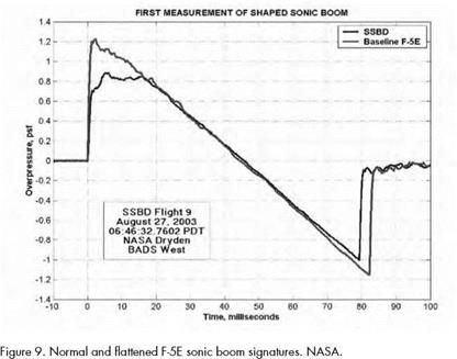
NASA’s Supersonics Project also put a new flight test on its agenda: the Lift and Nozzle Change Effects on Tail Shocks (LaNCETS). Both the SSBD and Quiet Spike experiments had only involved shock waves from the front of an aircraft. Yet shocks from the rear of an aircraft as well as jet engine exhaust plumes also contribute to sonic booms—especially the recompression phase of the typical N-wave signature—but have long been more difficult to control. NASA initiated the LaNCETS experiment to address this issue. As described in the Supersonic Project’s original planning document, one of the metrics for LaNCETS was to "investigate control of aft shock structure using nozzle and/or lift tailoring with the goal of a 20% reduction in near-field tail shock strength.”[535]

NASA Dryden had just the airplane with which to do this: F-15B No. 837. Originally built in 1973 as the Air Force’s first preproduction TF-15A two-seat trainer (soon redesignated as the F-15B), it had been extensively modified for various experiments over its long lifespan. These included the Short Takeoff and Landing Maneuvering Technology Demonstration, the High-Stability Engine Control project, the Advanced Control Technology for Integrated Vehicles Experiment (ACTIVE),

and Intelligent Flight Control Systems (IFCS). F-15B No. 837 had the following special features: digital fly-by-wire controls, canards ahead of the wings for changing longitudinal lift distribution, and thrust-vectoring variable area ratio nozzles on its twin jet engines that could (1) constrict and expand to change the shape the exhaust plumes and (2) change the pitch and yaw of the exhaust flow.[536] It was planned to use these capa­bilities for validating computational tools developed at Langley, Ames, and Dryden to predict the interactions between shocks from the tail and exhaust under various lift and plume conditions.

Tim Moes, one of the Supersonics Project’s associate managers, was the LaNCETS project manager at the Dryden Center. Jim Smolka, who had flown most of F-15B No. 837’s previous missions at Dryden, was its test pilot. He and Nils Larson in F-15B No. 836 conducted Phase I of the test program with three missions from June 17-19, 2008. They gathered baseline measurements with 29 probes, all at 40,000 feet and speeds of Mach 1.2, 1.4, and 1.6.[537]

Several months before Phase II of LaNCETS, NASA specialists and affiliated researchers in the Supersonics Project announced significant progress in near-field simulation tools using the latest in computational fluid dynamics. They even reported having success as far out as 10 body lengths (a mid-field distance). As seven of these researchers claimed in August 2008, "[It] is reasonable to expect the expeditious develop­ment of an efficient sonic boom prediction methodology that will even­tually become compatible with an optimization environment.”[538] Of course, more data from flight-testing would increase the likelihood of this prediction.

LaNCETS Phase II began on November 24, 2008, with nine mis­sions flown by December 11. After being interrupted by a freak snow­storm during the third week of December and then having to break for the holiday season, the LaNCETS team completed the project with flight

tests on January 12, 15, and 30, 2009. In all, Jim Smolka flew 13 mis­sions in F-15B No. 837, 11 of which included in-flight shock wave mea­surements by No. 836 from distances of 100 to 500 feet. Nils Larson piloted the probing flights, with Jason Cudnik or Carrie Rhoades in the back seat. The aircrews tested the effects of both positive and negative canard trim at Mach 1.2, 1.4, and 1.6 as well as thrust vectoring at Mach 1.2 and 1.4. They also gathered supersonic data on plume effects with different nozzle areas and exit pressure ratios. Once again, GPS equip­ment recorded the exact locations of the two aircraft for each of the datasets. On January 30, 2009, with Jim Smolka at the controls for the last time, No. 837 made a final flight before its well-earned retirement.[539]

The large amount of data collected will be made available to indus­try and academia, in addition to NASA researchers at Langley, Ames, and Dryden. For the first time, analysts and engineers will be able to use actual flight test results to validate and improve CFD models on tail shocks and exhaust plumes—taking another step toward the design of a truly low-boom supersonic airplane.[540]