Category X-15 EXTENDING THE FRONTIERS OF FLIGHT

CHARLES H. FELTZ, NAA

Charles Henderson Feltz was born on 15 September 1916 on a small ranch near Channing, Texas. He graduated from Texas Technological College in 1940 with a bachelor of science degree in mechanical engineering. He joined the Los Angeles Division of North American Aviation the same year, serving in a variety of engineering positions for the design and production of the B-25. Following the war, Feltz became the design group engineer in charge of the design of the wing structure for the F-82 and F-86 series of aircraft. Between 1948 and 1956 Feltz was the assistant project engineer for the development of the FJ2 Fury and the F-86D Sabre, and in 1956 he became the project engineer and program manager for the X-15.-115

In 1962 Feltz became the chief engineer for the Apollo command and service module, and advanced to vice president and deputy program manager by 1970. When the Apollo program ended, he became the vice president and deputy program manager for the Space Shuttle orbiter. Between 1974 and 1976, Feltz was the vice president and technical assistant to the president of the North American Rockwell Space Division. In 1976 he became vice president of the North American Aerospace Operations Division of Rockwell International, and in 1980 he became president of the Space Transportation System Development and Production Division of Rockwell International. Feltz retired from Rockwell International in 1981.

Texas Tech named Feltz a distinguished engineer in 1967, and a distinguished alumnus in 1972. During his career Feltz received a variety of medals and honors from NASA and industry groups, including a NASA Distinguished Public Service Medal in 1981. Charlie Feltz, the common-sense engineer, passed away on 3 January 2003.

FLIGHT DAY

X-15 flights generally began early in the morning; indeed, most flight-testing at Edwards began early in the morning when the temperatures and winds in the high desert were lower. The ground crew had mated the X-15 to the NB-52 the day before and stayed all night or arrived early to prepare the airplane for the flight. Floodlights lit the scene as propellants and gases were loaded onto both the carrier aircraft and research airplane, and liquid-oxygen vapor drifted around the area, lending a surreal fog. When the X-15 pilot arrived, he generally went straight to the physiological support van to get into the David Clark full-pressure suit. Getting the suit on and hooking up the biomedical instrumentation took about 15 minutes once the program switched to the A/P22S-2 suits; the MC-2 suits had taken considerably longer.-1^5

When the ground crew was ready for the pilot to enter the cockpit, two technicians carried a portable cooling system and other equipment while they escorted the pilot from the van to the airplane-a scene vaguely similar to Cape Canaveral before a space flight. Oddly, the driver of the physiological support van in which the pilot donned the pressure suit made no particular effort to park near the X-15, forcing the pilot to walk across the ramp. A large ladder and platform were located alongside the X-15 to allow the pilot and his handlers easy access to the cockpit. The cockpit itself was large for a single-seat airplane, but the bulk of the pressure suit made it seem somewhat smaller. Nevertheless, most pilots found it had more than adequate room and some of the smaller pilots even had difficulty reaching all of the controls mounted far forward, since the seat was not adjustable. Once the pilot was in the cockpit, the ground crew hooked up a myriad of lines, hoses, and straps that provided life support and monitored the pilot’s biomedical data.

While this was happening, the pilot began going through the preflight checklist to verify the status of all the aircraft systems. Once this was completed (usually a 30-minute process), the ground crew closed the X-15 canopy. The cockpit suddenly seemed smaller since the canopy fit snugly around the pressure-suit helmet.

While this was happening, the ground crew was disconnecting the servicing carts used to prepare the NB-52 and X-15 for flight. At this point, the NB-52 started its engines and the carrier aircraft pilots went through their preflight checklist, taking about 10 minutes to complete the activity. The ground crew then closed up the NB-52 hatches and the mated pair taxied toward the runway accompanied by a convoy of a dozen or so vehicles. Edwards is a large base, and the aircraft had to taxi for 2 or 5 miles depending on which runway was active. One of the H-21 helicopters took off and performed a visual check of the runway to make sure no debris was present, then took up a position beside and slightly behind the bomber, preparing to follow it down the runway for as long as possible.

At the end of the runway, the ground crew removed the safety pins from the X-15 release hooks. When everybody signaled they were ready, the NB-52 took off and climbed to 25,000 feet while circling over Edwards to make sure the X-15 could make an emergency landing on Rogers Dry Lake. Once above 25,000 feet, the NB-52 turned toward the launch lake and began climbing to 45,000 feet, since at this altitude the X-15 could glide to an alternate lakebed if necessary. The NB-52 supply topped off the X-15 liquid-oxygen tank, and the inertial platform was receiving alignment data, but otherwise things were quiet. Chase-1 flew in formation with the B-52, observing the X-15 for leaks or other anomalies that might signal a potential problem.

The mission rules dictated that if a serious problem occurred on the NB-52 while the mated pair was on the way to the launch lake, the carrier aircraft would jettison the research airplane since the extra 30,000 pounds of dead weight under the right wing would undoubtedly be detrimental to saving the NB-52. Similarly, if something happened on the X-15 that looked like it would endanger the NB-52, the research airplane would be jettisoned. As Scott Crossfield later observed, "It was not heroics; it was simple mathematics. Better to lose one man than four." In reality, the X-15 stood a chance of surviving if it was jettisoned, especially if the X-15 pilot had some advanced notice. The major problem was that neither of the APUs aboard the X-15 was running during captive carry since there was not enough propellant to last more than about 30 minutes. During the climb-out, the NB-52 supplied all of the X-15’s electrical needs, as well as breathing oxygen and pressurization gas. If the carrier aircraft jettisoned the X-15, the pilot would have his hands full trying to get the APUs started using a small emergency battery since without the APUs the pilot had no flight controls, no radio, no anything. If the APUs started, the pilot could try to fly (with or without the engine) to a lakebed. Of course, the ejection seat was always an option. Fortunately, the program never had to find out what would happen in that scenario.-1161

FLIGHT DAY

The need for the various lakebeds was largely driven by a program requirement to always have a landing site available to the X-15 pilot if he needed it for any reason. Therefore, each flight was planned such that the X-15 could glide to an emergency landing site from any point on the flight path, although frequently the nearest site was behind the airplane and required the pilot to turn around, as illustrated in this drawing. The program used the emergency landing sites 10 times. (NASA)

At 12 minutes before the scheduled launch time, things began to happen. The X-15 pilot started both APUs and began to run through the prelaunch checklists. The pilot checked all of the X-15 systems, exercised the flight controls, tested the ballistic control system, and set all switch positions. Chase-1 observed the results of these tests and reported them back to the X-15 pilot. During this time, radar and radio communication with NASA-1 guided the carrier aircraft into position near the launch lake. Eight minutes before launch the NB-52 began a long sweeping turn back toward Edwards, coming onto the final heading about 4 minutes later. At the same time, the X-15 pilot began activating the propulsion system. At 2 minutes prior to launch the X-15 pilot started the data recorders, checked the ball nose one last time, and turned on the cameras. One minute prior to launch the XLR99 was set to precool and the igniter was set to idle. More checks were performed to make sure the engine looked ready to fire. The X-15 pilot took a deep breat h.[l7]

Three, two, one: launch. The X-15 separated from the NB-52 and began to fall. The launch was harder than most pilots initially expected because the X-15 went from normal 1-g flight while attached to the carrier aircraft to 0-g flight instantaneously. The X-15 also wanted to roll to the right because of downwash from the NB-52 wing and interference from the fuselage. The X-15 pilots usually had left roll input applied at the moment of launch, but the airplane still rolled – more so on some occasions than others.

The XLR99 start sequence was remarkably simple, a necessary attribute in the days before computerized control systems. The first step was to pressurize the propellant tanks with gaseous helium to ensure a smooth flow of propellants to the turbopump. Then the oxidizer system was precooled to ensure that the liquid oxygen did not vaporize between the propellant tank and the turbopump (vaporized liquid oxygen caused the turbopump to cavitate and go into an overspeed condition that resulted in an automatic shutdown). It required about 10 minutes to chill the oxidizer system. Next was the engine prime sequence that fed a small amount of liquid oxygen and ammonia to the turbopump. The igniter-ready light came on when the prime cycle began and the pilot turned on the igniter switch. This all happened before the X-15 dropped away from the NB-52. As the X-15 was falling, the pilot continued the engine start procedure. There were about 10 seconds available to light the engine before the pilot had to abort to the launch lake; that was time for two ignition attempts.-118

Pressing the pump-idle button to start the turbopump initiated the ignition cycle. The turbopump spooled up quickly and forced propellants into the first-stage igniter, where a spark plug ignited them. The propellants were then fed into the second-stage igniter chamber, where the flame generated by the first-stage igniter caused them to combust. The second-stage igniter produced 1,500 lbf-as much as one chamber on the XLR11.

The throttle quadrant was a "backwards L" slot located on the left console. The outer corner was the "idle" position, the bottom inside corner of the L corresponded to minimum throttle, and the most forward position was 100% power. Moving the throttle inboard opened the main propellant valves and forced 30 gallons per second of propellants into the main chamber, where they were ignited by the flame from the second-stage igniter. The pilots found early in the flight program that the engine did not ignite reliably at low-power settings, so they usually immediately

advanced the throttle to the 100% position. Although the XLR99 proved to be a remarkably reliable engine, it really did not like to throttle. Still, the capability provided a certain amount of research utility that would not otherwise have been available, although it also contributed to several in-flight emergencies when the engine decided it no longer wanted to work as its designers had intended.-1191

In an attempt to ensure that the entire propulsion system was in working order, NASA conducted a ground run before almost every flight. Although it was comforting to the X-15 pilot to know the engine indeed seemed to work, these tests also added a great deal of wear and tear to the engines and other systems. During ground runs, the pilot would allow the engine to stabilize at 100% thrust for 8 seconds, and then retard it to idle for 5 seconds before shutting the engine down. The pilot would then perform an emergency restart sequence that relit the main chamber at 75% thrust. The pilot would stabilize the engine for 5 seconds, reduce it to idle for a couple of seconds, and then shut it down. It all became routine.

Energy management started the instant the NB-52 released the X-15. If the XLR99 did not light in two attempts, the pilot would make an emergency landing at the launch lake. If the engine died within the first 30-40 seconds of flight, the pilot would turn around and make an emergency landing at the launch lake. After about 40 seconds of burn, the airplane would be too far away to make it back to the launch lake, but if the engine burned less than 70 seconds, it was unlikely the pilot could make it to Rogers Dry Lake. The 30-second period in between was why the program had a large assortment of intermediate lakebeds available.

Unfortunately, the technology did not exist to provide the pilot with an energy-management display, although NASA installed a rudimentary unit in X-15-3 toward the end of the flight program. It was up to the ground controller (NASA-1) to advise the pilot where to land if a problem developed during the flight. As flight attendants are fond of saying on every commercial airline flight, the nearest exit may be behind you. In many cases, the best landing site was an intermediate lake that the airplane had already passed at hypersonic velocities.

The intermediate lakes were more important for the high-speed flights than for the altitude flights. Given enough altitude, the X-15 could glide for over 400 miles-more than enough distance to make it back to Edwards from almost any point on the High Range. Every flight was supposed to have excess energy as the airplane arrived over Edwards, allowing some flexibility during the final approach. Nevertheless, part of why the program had an excellent safety record was that the pilots and flight planners always had contingency plans—even for the contingency plans.

Most X-15 flights were essentially in the vertical plane, and it was important to establish the proper heading back toward Edwards during the first 20 seconds after launch. Once the engine shut down, the ballistics was pretty well established for the next few minutes of flight. If there was a wind at the launch altitude (and usually there was), the NB-52 would crab as necessary to maintain the proper ground track during the final 10-minute turn. At 1 minute to launch, the NB – 52 pilot would turn to the desired launch heading and allow the carrier aircraft to drift. Since winds at launch did not seriously affect the X-15 trajectory, this minimized the workload on the X-15 pilot to obtain, and hold, the desired heading. After launch, any necessary heading corrections were made by the X-15 pilot using small bank angles while performing a 2-g rotation and accelerating from Mach 1 to 2 in about 20 seconds. Once the X-15 reached the desired pitch angle, the g-level was less than one, and no further turning corrections could be made until after completion of the reentry.-120

FLIGHT DAY

The design speed mission was flown at relatively low altitudes – from 100,000 to 110,000 feet. These were the essential heating flights that were used to validate the various theoretical and experimental (wind tunnel) results. The time at maximum speed was not spent flying straight and level since the pilot was conducting a series of rudder pulses and other maneuvers to optimize the heating on the side of the aircraft that was instrumented. The ability to exactly repeat these maneuvers from one flight to the next was critical for the ultimate success of the flight program and a tribute to the flying skills of the pilots. (NASA)

The thrust from the XLR99 could be terminated by one of two routine ways at the nominal end of burn. The most frequently used method was called "shutdown." When a specific set of flight conditions had been reached, the pilot would manually shut down the engine. Normally the pilot did this after a precalculated amount of time based on a stopwatch in the cockpit that started when the main propellant valves opened. After NASA installed the X-20 inertial systems later in the program, the pilot could also use inertial velocity to shut down the engine, and several of the high-altitude flights used the altitude predictor installed in X-15-3. The other type of thrust termination was called "burnout." In this method the pilot just let the engine burn until the propellants were exhausted and the engine quit.-121

The high-speed flights were conducted at fairly low altitudes (a relative term since the altitudes would have been considered extraordinary before the X-15 program began). For these flights, the X-15 was essentially an airplane; its wings generated lift, maneuvering was accomplished via a set of aerodynamic control surfaces, and the atmosphere created a great deal of drag and friction on the airframe. The pilot would begin a 2-g rotation to the desired pitch angle immediately after the engine lit. During this rotation the primary piloting task was to adjust the bank angle to attain and hold the desired heading back to Edwards. As he approached 70,000 feet, the pilot initiated a gentle pushover to come level at something between 100,000 and 110,000 feet. As the airplane came level, the pilot either stabilized his speed at some preset value to conduct various research maneuvers, or continued to accelerate to attain more speed. The X-15 liked to accelerate; even at the top end, it took only 6 seconds to accelerate from Mach 5 to Mach 6. The research maneuvers continued after engine burnout until the airplane decelerated to the point that no more useful data were forthcoming. These were the essential heating flights.[22]

Altitude flights began much the same way, except that the pilot continued a steep climb out of the atmosphere. The engine shut down on the way up and the airplane coasted over the top on a ballistic trajectory. The pitch angle, in conjunction with the shutdown velocity, established both the range and maximum altitude of the arc that would follow. As the airplane continued on the ballistic trajectory, it was committed to a steep descent back into the atmosphere. The pilot set up the angle of attack for reentry, performed a pullout to level flight after reentry, and then began a shallow descent during the glide back to Rogers Dry Lake. A combination of dynamic pressure (q), load factor (g), and structural temperature limited the reentry since the relaxation of one parameter resulted in an excess of one of the others. These flights spent between 2 and 5 minutes outside the atmosphere, much of that time in a weightless (i. e., no accelerations) environment. The ballistic control system allowed the pilot to maintain attitude control, but he could not change the flight path of the airplane. Contrary to popular lore, as fast as it was, the X – 15 never flew anywhere near fast enough to attain orbital velocities or altitudes.-1231

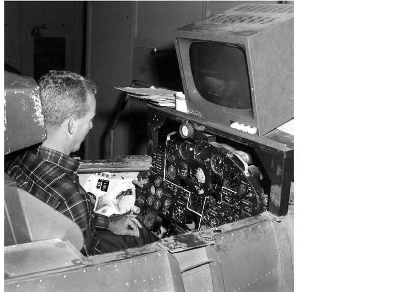
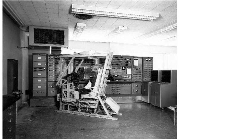
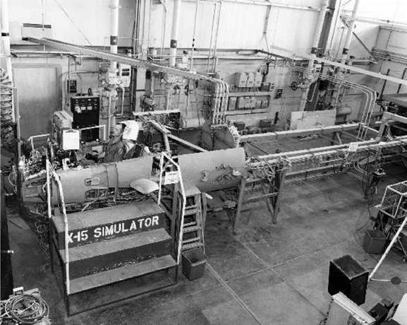
For the next few minutes, the calls from NASA-1 were primarily comparisons between the planned profile (on the plot boards) and the actual radar track of the airplane. These let the X-15 pilot know how well he had flown the exit phase and, more importantly, what maneuvers might be required during reentry. If he was "high and long," he would expect to make an immediate turn and apply the speed brakes during the latter part of the reentry. If he was "low and short," he would expect a straight-ahead glide with brakes closed. A "left of course" call would alert him to expect a right turn to a new heading after reentry. The ability to comprehend some of these energy-management subtleties while simultaneously controlling the aircraft’s attitude and subsystems, and accomplishing test maneuvers was one of the goals of the X-15 simulator training.-1241

Perhaps surprisingly, the altitude flights required a longer ground track than the high-speed flights. This was primarily because the airplane covered many miles while it was outside the atmosphere. Let us use the two maximum performance flights as comparative examples. Joe Walker’s 354,200-foot altitude flight required a ground track of 305 miles to climb out of the atmosphere, coast to peak altitude, reenter, make the pullout, and then slow to land. On the other hand, Pete Knight’s 4,520-mph speed flight only took 225 miles, mainly because the airplane slowed quickly after engine burnout since the speed flights occurred in a relatively dense atmosphere.-1251

FLIGHT DAY

Surprisingly, the X-15 spent more time at higher Mach numbers during the altitude missions than it did during the speed missions. This is because there is less aerodynamic drag at high altitudes and the airplane coasted at high velocities for longer while it was outside the atmosphere. The altitude missions were particularly demanding on the pilot since even small deviations from the planned profile could result in overshooting the target altitude. The ballistic control system was required to control the attitude of the airplane during these missions, most of which were flown by X-15-3 since the MH-96 adaptive control system provided more redundancy. (NASA)

During the envelope expansion and heating flights, the pilots performed a specific set of maneuvers (rudder pulses, angle-of-attack changes, and rolls) to evaluate the stability and control of the airplane in various flight regimes. Many times these maneuvers were near the limits of controllability for the airplane, and well-practiced contingency plans were always at the ready. Other tests provided information on control effectiveness, aerodynamic performance, lift-to-drag ratio, and aero-thermo loads. All of these maneuvers required that the pilot fly at a specific speed, attitude, and altitude while gathering the data. Often, the program needed to exactly duplicate the profile on subsequent flights to eliminate variables from the data, a decided challenge before the advent of computerized flight-control systems.-126

As Milt Thompson later observed, "This is the kind of thing a research pilot is required to do to earn his money-accomplishing good maneuvers for data purposes. Flying the airplane is just something the pilot does to get the desired test maneuver. He can be the greatest stick and rudder pilot in the world, but if he cannot do the required data maneuvers, he is worthless as a research pilot." Most of the X-15 pilots were very good research pilots.-127

Assuming all went as planned, the X-15 arrived back at Edwards and set up a high key (the highest point of the final approach to a runway) at approximately 35,000 feet and 290 to 350 mph. As he approached Edwards, the X-15 pilot began dumping any residual propellants to lower the landing weight and to get rid of potentially explosive substances. It also made a convenient way for the chase planes to find the small X-15 in the vast skies over the high desert. The X-15

then entered a 35-degree banking turn while maintaining 250 to 300 knots. The pilots normally turned to the left, although each pilot seemed to develop a preference, and it really did not matter much. At the completion of the turn, the X-15 was approximately 4 miles abeam of the intended touchdown point at 18,000 feet altitude headed in the opposite direction of the landing runway (this was low key). The pilot then continued around 180 degrees, turned onto final at about 8,000 feet and 300 knots, and flared at around 1,000 feet. The pilot jettisoned the ventral rudder, lowered the landing flaps as the airplane came level at about 100 feet, and deployed the landing gear at 215-225 knots. Touchdown was generally made at around 190-200 knots. The pilot judged the possible crosswinds by the simple expedient of looking at the smoke from flares beside the runway.-1281

Unsurprisingly, not all flights arrived at high key exactly as planned. At least one flight arrived at high key at 80,000 feet and over Mach 3.5, another made high key at only 25,000 feet, and one made a straight-in approach because it was too low on energy when it arrived at Edwards. Despite these variances, the majority of X-15 touchdowns were made within 2,000 feet of the intended spot, although a couple of flights missed by over 4,000 feet. Neil Armstrong managed to miss by 12 miles-fortunately, Rogers is a large dry lake. The X-15 generally slid for 8,000-10,000 feet before coming to a stop, chased by a convoy of rescue and support vehicles.-291

The general concept was similar to that ultimately adopted as the terminal area energy – management maneuver used by the Space Shuttle. The proven ability of the X-15 (and later the heavyweight lifting bodies) to make unpowered approaches was one reason the Space Shuttle program decided it could eliminate the complexity of landing engines and make the Orbiter a glider. It is another enduring legacy of the X-15 program.-301

The X-15A-2

After Jack McKay’s emergency landing in X-15-2 on 9 November 1962, North American proposed modifying X-15-2 to an advanced configuration capable of reaching Mach 8 velocities. NASA in general and Paul Bikle in particular were not particularly enthusiastic and felt the Air Force should simply repair the aircraft to its original configuration or retire it altogether. Many researchers believed that the Mach 8-capable X-15A would be of limited value for aero-thermo research. However, NASA did not press its views, and on 13 May 1963 the Air Force directed North American to repair and modify the aircraft at a cost of $4.75 million. The advanced aircraft was intended to evaluate an air-breathing hypersonic research engine (HRE) being developed at Langley. It was designed to reach 8,000 fps at an altitude of 100,000 feet, and a dynamic pressure of 1,000 psf. Heating rates up to 210 Btu per square foot per second were expected, with peak structural temperatures approaching 2,400°F.[231

The modifications did not significantly alter the physical appearance of X-15A-2. The wingspan was still 22.36 feet, but the airplane was 29 inches longer due to a plug in the center of gravity compartment between the propellant tanks. Perhaps the most obvious change was the addition of external propellant tanks on each side of the fuselage below the wings. These allowed the airplane to carry approximately 70% more propellant, a necessary ingredient in raising performance to 8,000 fps. The tanks provided an additional 60 seconds of engine burn time, for a total of 150 seconds at 100% power. Other modifications included adding hydrogen-peroxide tanks within extended aft-side fairings to supply the turbopump for the longer engine burn times, and additional pressurization gas in a spherical helium tank just behind the vertical stabilizer.12321

The fuselage extension provided additional internal volume for experiments, and the center-of – gravity compartment access doors could accommodate optical windows looking up or down. The compartment could also accommodate a liquid-hydrogen tank, with a total capacity of 48 pounds, to fuel the ramjet mounted under the fixed portion of the ventral stabilizer, but it appears NASA never actually installed the tank. Perhaps the most difficult part of incorporating this extension was moving the B-52 pylon attach points to maintain the vertical stabilizer in the appropriate position under (through) the NB-52 wing.-12331

North American strengthened the landing gear using a strut that was 6.75 inches longer than the original. This provided 33 inches of ground clearance to the bottom of the fixed ventral stabilizer; the expected ramjet was 30 inches in diameter. The new strut provided a 1,000-pound increase in allowable landing weights, but there was some concern over the effects of the longer strut on nose-wheel and forward fuselage loads. In an attempt to provide an additional margin of safety, the nose-gear trunnion was mounted 9 inches lower (effectively lowering the nose gear by the same amount), allowing an attitude at nose-gear touchdown that was similar to that of the basic airplanes.12341

Instead of the trapezoidal windows on the original airplanes, North American installed elliptical windows that used three panes of glass to withstand the increased temperatures at Mach 8. The outer pane was 0.65-inch-thick fused silica, the middle pane was 0.375-inch alumino-silicate, and the inner pane was 0.29-inch laminated soda lime glass. This time the company mounted the outside windshield-retaining frame flush with the glass to prevent the reoccurrence of the flow heating experienced early in the program.-12331

The X-15A-2 modification also included a "skylight" hatch. Two upward-opening doors, 20 inches long by 8.5 inches wide, were installed above the instrument compartment behind the cockpit to expose cameras and other experiments. North American revised the normal research instrumentation elevator so that the upper shelf could extend upward through the open hatch if needed. The modifications also included additional data recorders: five 36-channel oscillographs, eight three-channel oscillographs, two 14-track tape recorders, one 24-cell manometer, and one cockpit camera. In addition, a new 86-channel PDM telemetry system was used to transmit data to the ground in real time.-12361

The accident had seriously damaged the outer portion of the right wing. North American found that it could adequately repair the main wing box, but the outer 41 inches were a total loss. With the government’s concurrence, the company modified the wing box to support a replaceable outer panel that allowed the testing of various materials and structures during hypersonic flight. The panel provided with the airplane (and the only one that apparently ever flew) was similar in construction and materials to the standard X-15 wing except that it was equipped with a 26.7 by 23-inch access panel that allowed access to an extensive amount of research instrumentation.-12321

FUSELAGE EXTENSION


HELIUM / TANK


WINDSHIELD


RAMJET


EXTERNAL TANK


— EXTENDED MAIN GEAR


REMOVABLE WING TIP


The X-15A-2

The X-15A-2

TANKS

After Jack McKay’s emergency landing at Mud Lake, the Air Force had North American rebuild the X-15-2 with several modifications intended to allow flights to Mach 8 to support ramjet propulsion research. The X-15A-2 was designed to reach 8,000 fps at an altitude of 100,000 feet, and a dynamic pressure of 1,000 psf. Heating rates up to 210 Btu per square foot per second were expected, with peak structural temperatures approaching 2,400 degrees Fahrenheit.

A 29-inch fuselage extension provided a larger center-of-gravity compartment to hold a liquid hydrogen fuel tank for the proposed ramjet, and external tanks carried additional propellants for the XLR99. (NASA)

NASA conducted wind-tunnel tests of the X-15A-2 during the summer and fall of 1963. The tests indicated that there was little aerodynamic difference between the modified X-15A-2 without external tanks and the basic X-15. Despite the anticipated similarities, engineers decided it was prudent to conduct an abbreviated flight series to verify that the airplane still handled satisfactorily. Stability and control maneuvers conducted during the initial flights of the X-15A-2 largely verified the wind-tunnel predictions. However, the verification took significantly longer than expected when the program encountered trouble with the modified landing-gear system.-1238

North American completed final assembly of X-15A-2 in Inglewood on 15 February 1964, and the Air Force accepted the airplane on 17 February, three weeks ahead of schedule and slightly below budget. The airplane was, however, 773 pounds overweight, a condition that was expected to reduce the maximum velocity somewhat. The design launch weight was 49,640 pounds, and propellants accounted for 32,250 of these pounds (18,750 pounds internally and 13,500 pounds in the external tanks). Subsequent modifications would add another few hundred pounds in empty weight. North American delivered the airplane to the FRC on 18 February and an "official" government acceptance ceremony took place on 24 February.-239

flight was to check out the various systems, evaluate the handling qualities of the modified airplane, and gain preliminary experience with the ultraviolet stellar photography experiment

(#1).[240]

It was not bad for a "checkout" flight. Using 77% thrust, Bob Rushworth reached Mach 4.59 and 83,300 feet. In an ironic twist, Jack McKay, who had been injured on the flight that damaged the airplane, was the NASA-1 controller. As expected, Bob Rushworth reported that the modified X- 15A-2 handled much like a basic X-15. Static longitudinal stability remained about the same, despite a 10% forward shift in the center of gravity. The already low directional stability of the unmodified airplane was somewhat lower in X-15A-2, but Rushworth did not think it posed a significant threat to safety. The longitudinal trim characteristics of the modified airplane were essentially unchanged up through Mach 3 at angles of attack up to 15 degrees. The modified airplane had a trim capability reduced by approximately 3-5 degrees at higher angles of attack and Mach numbers.*241

Things got more exciting on the second flight (2-33-56). Shortly after a maximum Mach number of 5.23 was obtained, the nose gear unexpectedly extended as the airplane decelerated through Mach 4.2. After the flight Rushworth wrote, "Everything was going along fine and just about the time I was ready to drop it over [lower the nose] I got a loud bang and… the resulting conditions that I had gave me quite a little bit of concern because the airplane began to oscillate wildly and I couldn’t seem to catch up with it. I put the dampers back on and stuffed the nose down to about 5 degrees angle of attack and it seemed to be normal then except I had a sideslip and I was then required to use left roll to hold the airplane level. A couple of seconds later I realized that this sound that I had heard was very much similar to the nose gear coming out in the landing pattern so that was the only thing I could think of. I announced that and then a few seconds later I began to get smoke in the cockpit, quite a little bit more than I had ever seen before. This partially confirmed that the nose gear, at least the door was open. I wasn’t sure that the gear was out but it was; there was enough of an explosion there to make me think that the gear was out."[242]

For the time being, the chase planes were of no help in confirming the problem since they were some 10 miles below the X-15. Jack McKay as NASA-1 could not help much either, since no emergency procedures existed for this particular failure. McKay did advise Rushworth that it would probably be best if the X-15 remained at high altitude until it had slowed considerably, thereby easing the aero-thermo loads on the extended nose gear. At one point NASA-1 advised Rushworth to use the brakes to slow down a bit, but Rushworth had other ideas: "No, I don’t want to get brakes out, I want to get the damn thing home." Fifty miles away from Edwards, the X-15 was still traveling at Mach 2.5 and McKay advised Rushworth, "Let’s go max L/D, Bob. You’re looking OK now. Your heading is good. You’re on profile. Looks like you’ve got plenty of energy."*241

The chase planes finally spotted the X-15 as it was descending 20 miles northeast of Edwards. Despite the degraded control and increased drag resulting from the extended nose gear, Bob Rushworth was doing fine. Joe Engle in Chase-3 verified that the nose gear appeared to be structurally sound and in the locked-down position. As for the tires, Engle reported, "OK, Bob, your tires look pretty scorched; I imagine they will probably go on landing." There was a worry, however, that the oleo strut had also been damaged by the heat and dynamic pressure; if it failed on landing, the X-15 could break in half or worse. There seemed to be little choice. Engle was right-the tires disintegrated shortly after the nose gear came down, but Rushworth managed to stop the airplane without serious difficulty.*244*

An investigation revealed that aerodynamic heating was the cause of the failure. The expansion of the fuselage was greater than the amount of slack built into the landing gear release cable. This caused an effective pull on the release cable that released the uplock hook. An outward bowing of the nose gear door imposed an additional load on the uplock hook. The load from both of these sources caused the uplock hook to bend, allowing the gear to extend. Engineers duplicated this failure in the High-Temperature Loads Calibration Laboratory by simulating the fuselage expansion and applying heat to the nose-gear door.[245]

The same stability and control data flight plan was duplicated for the next X-15A-2 light (2-34­57) on 29 September 1964. Again, shortly after reaching a maximum Mach number of 5.20, Bob Rushworth experienced a similar but less intense noise and aircraft trim change at Mach 4.5-the small nose-gear scoop door had opened. In his post-flight report Rushworth noted, "Yes, I sensed it was the little door, because the magnitude of the bang when it came open wasn’t as large as the other experience." During the normal gear-extension sequence, air loads on the small door pulled the nose gear door open to assist in the extension of the nose gear. Although not as serious a failure as that on the previous flight, it again precluded obtaining dampers-off stability data. NASA redesigned the nose-gear door to provide positive retention of the scoop door regardless of the thermal stresses. Engineers also modified the other two airplanes since the basic failure mode was common.[246]

To check out the modifications to the nose gear, the program decided on a low-speed flight (2­35-60) to a maximum Mach number of 4.66. The flight planners decided to give Bob Rushworth a break after the two previous adventures, so Jack McKay made this flight, which went off without a problem. The nose gear performed normally.-12471

Rushworth was in the cockpit again for the next fight (2-36-63) of X-15A-2 on 17 February 1965. In a run of bad luck that is hard to fathom, this time the right main skid extended at Mach 4.3 and 85,000 feet. In his post-flight report Rushworth wrote, "Jack [McKay, NASA-1] was talking away and things were going along real nice and I couldn’t seem to get a word in there to tell him that I had a little problem. It took several seconds to get the airplane righted and dampers back on, very much similar to the nose gear coming out. Once I got it righted, I realized that I had a tremendous sideslip, I guess 4 degrees, and it took a lot of rudder deflection to get sideslip to zero. This persisted all the way down until I got subsonic. Once I had gone subsonic the airplane handled reasonably well." Again, the chase pilot was able to verify that the gear appeared structurally sound, and Rushworth managed to make a normal landing. When Rushworth finally got out of the airplane, he turned around and kicked it-enough was enough. Post-flight inspection revealed that the uplock hook had bent, allowing the gear to deploy. Again, aerodynamic heating was determined to be the source of the high load on the uplock hook.[248]

NASA flew five more X-15A-2 flights (2-38-66 through 2-42-74) before the envelope expansion program was begun. These flights were primarily conducted to study stability and control, but they also included landing-gear performance tests. Each flight carried the ultraviolet stellar photography experiment but obtained little useable data because of problems in maintaining the precise attitudes required for the experiment. Fortunately, the landing gear seemed to behave throughout these flights, but it had caused this portion of the flight program to take longer than expected.[2491

The engineers had always had some concerns about operating the X-15A-2 with the 23.5-foot – long, 37.75-inch-diameter external tanks. These attached to the airplane structure within the side fairings at fuselage stations 200 and 411. Propellant and gas interconnects ran through a tank pylon that was located between stations 317 and 397 and was covered by a set of retractable doors after the tanks were jettisoned. The left tank contained about 793 gallons of liquid oxygen in one compartment and three helium bottles with a total capacity of 8.4 cubic feet. The right tank contained about 1,080 gallons of anhydrous ammonia in a single compartment. The empty left tank weighed 1,150 pounds and the empty right tank weighed only 648 pounds; when they were full of propellants, they weighed 8,920 pounds and 6,850 pounds, respectively. Note that the left tank was over 2,000 pounds heavier than the right tank when they were full. To minimize weight and cost, the government had opted not to insulate the liquid-oxygen tank. As a result, the evaporation rate was high enough that the engineers considered the NB-52 top-off supply to be marginal. If a flight encountered a long hold time prior to launch, it might prove necessary to abort the mission and return to Edwards due to excessive liquid-oxygen boil – off.[250]

The use of external tanks on the X-15A-2 was unique in that the pilot had to jettison the tanks from the aircraft. The structural limitations of the aluminum tanks and the degraded handling qualities dictated that the maximum allowable Mach number with the external tanks was 2.6, so the pilot had to jettison the tanks before reaching that speed. In addition, a landing was not possible with the tanks installed because of the increased drag and a lack of ground clearance. Hence, the program expended considerable effort to ensure the tanks would jettison when commanded.-125^

Each tank was forcibly ejected from the airplane during flight through the use of fore and aft gas – cartridge ejectors and a forward solid-propellant sustainer rocket that imparted pitching and rolling moments to the tank after it had been ejected. For a normal empty tank jettison, both sets of gas cartridges fired and the nose rocket ignited. In the case of an emergency jettison when the tanks were full, only the nose gas cartridge fired.

The tanks were relatively expensive, so they were equipped with a recovery system that included a drogue and a main parachute. The drogue chute deployed from its nose compartment immediately after separation, and the main descent parachute deployed when a barometric sensor detected the tanks passing through 8,000 feet. Although the engineers expected some impact damage, they believed it was possible to refurbish the tanks at a reasonable cost.-252!

Wind-tunnel tests indicated that satisfactory separation characteristics existed when the dynamic pressure was less than 400 psf and the angle of attack was less than 10 degrees; acceptable separation probably existed for dynamic pressures up to 600 psf. At higher angles of attack and dynamic pressures, researchers expected the tanks to roll excessively and to pitch up within close proximity to the airplane. Tank separation characteristics with partly expended propellants were unknown and were a potential problem since there were no slosh baffles or compartments for center-of-gravity control. The researchers expected the full-tank ejection characteristics to be satisfactory for any reasonable flight conditions that might occur within 15 seconds of launch.-253!

Prior to the first flight using external tanks, the Air Force conducted two dummy tank jettison tests with X-15A-2 located over a 10-foot-deep pit in the ground beside the ramp. Technicians constructed a pair of beams with similar mass and inertia properties to simulate empty tanks. Preloaded cables attached to the beams applied simulated aerodynamic drag and side loads. The first test used a single set of ejector cartridges at simulated air loads of 400 psf, 5 degrees angle of attack, and 3 degrees of sideslip. The second test used two sets of ejector cartridges at a simulated dynamic pressure of 600 psf. Both tests were successful, and high-speed motion pictures showed good separation characteristics. During the tests, the X-15 APU supplied hydraulic and electrical power, and engineers engaged the SAS to observe its reaction to the separation, which was satisfactory.-2541

Подпись: PARACHUTE CONE

Подпись: RIGHT HAND NH3 (6850 lb FULL)
Подпись: AFT EJECTOR
Подпись: ROCKET THRUSTER FORWARD EJECTOR—

The X-15A-2LEFT HAND LOX (3920 fb FULL)

The external tanks allowed carriage of approximately 70 percent more propellant, a necessary ingredient in raising performance to 8,000 fps. The tanks provided an additional 60 seconds of engine burn time, for a total of 150 seconds at 100-percent power. The tanks were 23.5 feet long and 37.75 inches in diameter. The left tank contained about 793 gallons of liquid oxygen in one compartment and three helium bottles with a total capacity of 8.4 cubic feet. The right tank contained about 1,080 gallons of anhydrous ammonia in a single compartment. The empty left tank weighed 1,150 pounds and the empty right tank weighed only 648 pounds; when full, they weighed 8,920 pounds and 6,850 pounds, respectively. (NASA)

Despite this, during a review leading up to the first flight, engineers expressed concern over the possible separation of partially filled tanks during an emergency. The wind-tunnel tests and the tank separation system only covered full and empty scenarios. What would happen if the pilot had to abort the flight during the first 60 seconds of powered flight while the engine was siphoning propellants from the external tanks? The initial response was that the tanks, as designed, would not withstand the loads imposed during a separation with a partial load. Engineers at the FRC and AFFTC considered installing a rapid propellant-dump system, installing a set of baffles in the tanks, or even providing a system that would allow the pilot to refill the tanks using internal propellants. All seemed too complicated given the time and money available to the program.[255]

After a great deal of consultation among the engineers, flight planners, and pilots, management decided to continue, at least for the time being. The risk was considered reasonable because the XLR99 had never encountered a premature shutdown from 100% thrust-all failures had occurred either during ignition or while throttling. If a failure happened during ignition, the tanks would be full and would not present a problem, and the plan called for no throttling during the high-speed runs. Nevertheless, engineers decided to add a third jettison button in the cockpit. This one, intended for use with partial tanks, would fire the forward gas cartridge and ignite the separation rocket-sort of a middle ground between the other scenarios.-1256

Although there were physical differences between the basic X-15 and the X-15A-2 without external tanks, their aerodynamic qualities were similar. With external tanks on the airplane,
however, some rather dramatic differences existed, with the general trend toward unfavorable characteristics. The offset center of gravity caused by the external tanks further complicated the overall control task. At launch with full tanks, the vertical center of gravity was approximately 9 inches below the aircraft waterline, moving upward as the engine consumed propellants. The pilot had to use additional nose-up stabilizer trim to counteract the nose-down pitch at engine ignition caused by this offset below the thrust vector. The heavier liquid-oxygen tank on the left side displaced the center of gravity 2 inches to that side, causing a left rolling moment that the pilot also had to counteract.-257!

The nominal flight profile for the speed missions was to maintain the airplane at a 12-degree angle of attack until it reached a pitch attitude of 34 degrees. The pilot held this climb attitude until the external propellant was depleted. Tank ejection occurred at approximately Mach 2.1 and

67.0 feet, and the pilot maintained an angle of attack of 2 degrees until the airplane reached

100.0 feet. The airplane then accelerated to maximum velocity.258

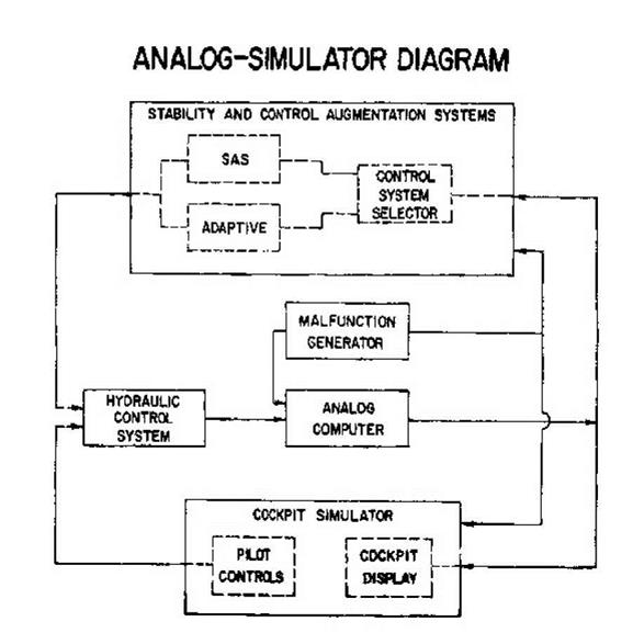
As was the case with the basic airplane, the simulator predicted poor handling qualities at high angles of attack, due primarily to the large negative dihedral effect caused by the presence of the ventral rudder. For a yaw damper failure with the speed brakes out, a divergent sideslip oscillation persisted above 6 degrees angle of attack. Although the pilot could damp this divergence, it required almost continuous attention and left little time for other tasks. The simulator showed that turning off the roll damper would eliminate the divergent yaw oscillation, but then the pilot would have to fly the airplane with less lateral directional stability. From the simulator studies it was determined that, because of the relatively low-altitude profiles required, the airplane could be safely flown after a roll and/or yaw damper failure if an angle of attack of less than 8 degrees was maintained. The program accepted this restriction for the initial envelope expansion flights. However, for the projected ramjet tests, which required flights at high dynamic pressures, a divergence of this type could occur too rapidly for the pilot to take corrective action. Hence, NASA decided to provide a redundant yaw damper, similar to the ASAS used for the roll axis. The FRC began initial design work, but the flight program ended before the system was completed.-1259!

The final ground-based external tank test took place on the Rocket Engine Test Facility where X – 15A-2 had completed a full-duration engine run with the external tanks installed on the aircraft. Engineers had already corrected deficiencies uncovered during several earlier tests.268

The expected performance of X-15A-2 represented a significant improvement over the demonstrated 6,019 fps of the basic aircraft. With external tanks and the ventral rudder, the estimated velocity was between 7,600 and 7,700 fps at 120,000 feet. Replacing the ventral with an assumed ramjet configuration would decrease that to about 7,200 fps at 118,000 feet, a result of increased weight and drag for the ramjet configuration. This performance was, however, appreciably less than the design goal of 8,000 fps at 100,000 feet. As a result, Reaction Motors was investigating the development of a new injector and nozzle to provide additional thrust in an attempt to bring the performance back up to 8,000 fps. Again, the end would come before the company completed the work.261

The length of time the airplane could remain at high velocity and dynamic pressure determined the amount of useful data about the ramjet that could be obtained. Researchers expected that X – 15A-2 could stay above 7,000 fps for 50 seconds and above 6,000 fps for 110 seconds per flight. For ramjet tests that required steady conditions (that is, at a relatively constant velocity and dynamic pressure), the pilot would throttle the XLR99 to minimum and extend the speed brakes so that low acceleration existed. The expected stabilized test time for this configuration was approximately 14 seconds at 7,000 fps and 40 seconds at 6,000 fps.268

The first flight (2-43-75) with empty external tanks was on 3 November 1965, the only flight launched from Cuddeback, about 60 miles north of Edwards. Bob Rushworth jettisoned the tanks at Mach 2.25 as the airplane passed through 70,300 feet, and took the airplane to Mach 2.31 and 70,600 feet before landing at Rogers Dry Lake after a flight of only 5 minutes and 1 second (the shortest non-emergency powered flight of the program). Post-flight analysis indicated that the handling qualities were essentially as predicted by the simulator. Rushworth, who for a change was flying without deploying part of the landing gear, commented that he thought the "roll stability was significantly less than I had expected," but the "longitudinal control wasn’t quite as bad" as he had anticipated.-126^

Two ground-based mobile trackers, each with 150-inch lenses on 35-mm Mitchell cameras running at 72 and 48 frames per second, provided photographic coverage of the tank separation. In addition, six Askania tracking cameras recorded the tank recovery system. Because the events took place at quite a distance, the resulting image size was small and researchers could only make a qualitative analysis of the event. The tanks separated cleanly from the aircraft; however, it appeared that the tanks did not rotate nose down as much as expected. They exhibited a tumbling action during flight with the drogue chutes attached, and tended to trim at an angle of attack of about -110 degrees. The drogue chutes occasionally collapsed during flight, so the engineers lengthened the drogue chute riser for future flights. Impact with the desert destroyed the liquid-oxygen tank after the nose cone containing the main descent chute did not separate properly. The Air Force recovered the ammonia tank in repairable condition. The tumbling action of the tanks increased the total drag and the tanks fell short of their predicted impact points-the ammonia tank landed 2.3 miles short and 0.6 mile to the left, while the liquid-oxygen tank landed 2.7 miles short and 1.6 miles to the left. This was still well inside the bounds of the Edwards impact range and did not represent a problem.-264

Joe Engle ended up being the only X-15 pilot who would get to fly the next lifting-reentry vehicle, the Space Shuttle. He also has the distinction of being the only person to fly back from orbit, on the second Space Shuttle flight (STS-2). Milt Thompson said that "Joe Engle seemed to have a charmed relationship with the X-15" because for the most part all of Engle’s flights went according to plan. However, not everybody would agree with that assessment of his 15th flight.

On 10 August 1965, Engle took X-15-3 to 271,000 feet-his second flight above 50 miles.

Mission rules stated that the X-15 pilot should fly an alternate low-altitude mission if the yaw damper channel on the MH-96 failed during the first 32 seconds of flight. This was because it was unlikely the airplane could make a successful reentry with a failed yaw damper. On this flight (3-46-70), the yaw channel failed 0.6 seconds after the X-15 dropped off the pylon. Engle reset the damper and did not feel obligated to fly the alternate profile since the damper successfully reset. It was a temporary reprieve, however. The damper failed again 19 seconds later; the reset was successful for at least 10 seconds until it failed again. The damper failed three times in the first 32 seconds of flight. Remarkably, Engle successfully flew the mission, although he missed some of the profile for various reasons, including a preoccupation with resetting the failing yaw damper.264

At the end of 1965, NASA could see that the end of the X-15 program was in sight. Researchers had long since completed the originally envisioned basic flight research, and the aircraft were now primarily experiment carriers, although X-15A-2 was still extending the flight envelope somewhat. However, plans to use X-15A-2 as a hypersonic ramjet test bed began to unravel when, on 6 August 1965, Secretary of Defense Robert S. McNamara disapproved the funding necessary for the effort.266

Under the best-case scenario, the FRC anticipated that the flight program using the basic X-15s would begin winding down at the end of 1967 when X-15-3 began receiving its delta-wing modifications. By the end of 1969, X-15-1 would be retired, leaving only X-15A-2 and the newly redelivered delta-wing X-15-3 in service. X-15A-2 would finish its ramjet tests in mid-1970, transferring all flight activity to the delta wing.-267

Paul Bikle had long believed that any extended operation of the X-15 program beyond its original objectives was unwise and hard to justify in view of the high cost and risk involved. As early as 1961, he had suggested the end of 1964 as a desirable termination date. As time went on, Bikle felt that continued extensions of the program were becoming increasingly hard to justify, and he personally had strong doubts that either the delta wing or the HRE would ever reach flight status on an X-15. In spite of these personal misgivings, Bikle continued to support the program in his public statements.268

1965 FLIGHT PERIOD

January 1966 was much like December 1965 in the high desert-wet. Between 12 November and 1 December 1965 more than 3 inches of rain had fallen, and 2 more inches fell during December. NASA described Rogers, Three Sisters, Silver, and Hidden Hills as "wet," while Mud Lake was only "damp." Over 95% of Cuddeback was under water and there was visible snow at Delamar. A lack of landing sites effectively grounded the X-15 program.268

This gave the program time to do maintenance on the airplanes and incorporate various modifications. For instance, engineers installed the Honeywell IFDS, finally, on X-15-3 along with a new Lear Siegler-developed vertical-scale instrument panel. All of the instrumentation wiring on this airplane was removed and replaced with new four-conductor shielded Teflon wire. It received the modifications necessary to carry the wing-tip experiment pods, and the third skid and stick – kicker needed for higher landing weights were installed.278

The pilots were not greeting the new X-15-3 instrument panel with overwhelming enthusiasm. Paul Bikle opined that "there has been some evidence of reluctance to accept the vertical-scale, fixed-index [tape] instruments." Bikle noted that previously "no objective evaluation of the suitability of the panel for the X-15 mission had been made." To correct this, engineers installed a duplicate of the panel in the fixed-base simulator and conducted runs using "measurable flight control and pilot performance parameters in a comparison of the Lear panel with the traditional panel."278

Of all the performance measures taken, only two showed consistent and significant differences. These were the absolute error in velocity at power reduction and the burnout altitude; in both cases, the statistical results favored the Lear panel. An examination of the altitude and velocity indicators on both panels showed that the differences were the result of high-scale resolution on the Lear instruments, which was almost twice that of the traditional panel instruments. The pilots were still not altogether happy with the new panel, but they no longer mistrusted it.222

The X-15A-2

For most of the flight program, the X-15 used an instrument panel that contained conventional instrumentation. In 1965, Lear Siegler developed a new panel for X-15-3 that used vertical-scale instruments that were supposed to provide enhanced situational awareness for the pilot. Similar instruments were being incorporated into the latest generation of Air Force fighters about the same time. At first, the new instrument panel was not met with overwhelming enthusiasm from the X-15 pilots, but eventually they came to accept the new instruments, although having two very different cockpit configurations complicated the simulators and training regiments. (NASA)

During this down period, X-15A-2 received a new Maurer camera to replace the Hycon unit in the center-of-gravity compartment. This was not as simple as it sounded and took almost eight weeks of work. X-15-1 received a modification that allowed ground personnel to easily remove or replace the wing-tip pods as needed to support various experiments. NASA could now swap the pods between X-15-1 and X-15-3, and was manufacturing a second set of pods.[273]

As January passed with no relief from the wet lakebeds (another half inch of rain fell at Edwards, with more snow on the upper areas of the High Range), NASA performed more modifications on the airplanes. Because the increase in stiffness of the main skids and the addition of the third skid transmitted higher loads through the structure to the nose gear, engineers decided to reinforce the skin on X-15-1 between fuselage stations 91 and 106. The Air Force sent the NB-52B to Tinker AFB for major maintenance, leaving her older sister to support the flight program, assuming the lakebeds ever dried out. The carrier aircraft returned on 8 April and the AFFTC spent the next five weeks modifying it to carry the heavier X-15A-2.[274]

The X-15A-2

The X-15A-2 configuration was tested in a variety of wind tunnels, including one at the NASA Jet Propulsion Laboratory in Pasadena, California. The JPL tests centered around determining the effects of shock-wave impingement on the proposed ramjet and finding an alternate vertical – stabilizer configuration to provide enhanced stability at Mach 8 while carrying a ramjet under the ventral stabilizer. (NASA)

NASA also used the time to complete various analyses, including a complete simulation of reentry profiles at the increased weights currently flown by the airplanes. The ground rules were that reentries would be limited to 1,600 psf using an angle of attack of 20 degrees. To avoid exceeding the structural limitations of the airplanes, NASA decided to restrict X-15-1 to altitudes under 265,000 feet and X-15A-2 to less than 250,000 feet. Mostly because it was equipped with the MH-96, NASA allowed X-15-3 to operate up to 360,000 feet. These restrictions were not really a problem since the program had already reached the maximum altitude it was planning on, although the first two airplanes would bump into these limits on several future flights.-1275

The simulations showed that, as currently configured, X-15A-2 should be able to reach a maximum velocity of 7,500 fps without the ramjet and 7,100 fps with the ramjet, both at 120,000 feet. These velocities assumed a launch weight of 51,650 pounds with the use of external tanks and an XLR99 burn time of 152 seconds. Based on these simulations, flight planners decided to conduct the X-15A-2 envelope-expansion program with the ventral on, primarily because it most closely resembled the planned ramjet configuration. However, the program was short of ventral rudders, and it was uncertain whether economic constraints would allow each flight to use one.-1275

More importantly, Langley and the Jet Propulsion Laboratory conducted wind-tunnel tests to investigate shock-wave systems affecting the proposed ramjet installation on X-15A-2. Researchers worried that shock waves impinging on the ramjet could affect inlet and engine performance, structures, and structural heating. The tests provided data for angles of attack between -5 and +20 degrees at Mach numbers between 2.3 and 4.63. A review of the data

showed that a shock wave emanating from the forward tip of the landing-gear skid would impinge on the ramjet inlet at all Mach numbers, and did not significantly vary with the angle of attack. These tests also showed that there was a complex shock impingement around the ventral stabilizer in general. Apparently, these data went unnoticed.-1272

By the beginning of April, the weather had improved considerably. The Air Force was in the process of repairing and re-marking Rogers, Grapevine, and Mud Lake. Cuddeback was dry but still too soft to re-mark. All of the other lakes were drying rapidly and were ready to use by the end of the month.-1278-

THE FOLLOW-ON PROGRAM

During the early 1960s, the X-15 was the only platform that could realistically carry a useful payload above the Earth’s atmosphere and return. Researchers had been making use of various sounding rockets that provided relatively inexpensive access to the upper atmosphere from a variety of locations around the world. However, in general these rockets had very small payload capabilities, could not provide much in the way of power or controlled flight, and were usually not recoverable. On the other hand, although the X-15 was very limited in where it could fly (over southern California and Nevada), it could provide a fair amount of power, it was at least somewhat controllable for aiming purposes, and, most importantly, it was recoverable.

EXPERIMENT ACCOMMODATIONS

Although the X-15 provided some internal space for experiments, many researchers wanted specific views of the world outside or to have their experiments located away from the "noise" of the airplane. This gave rise to several modifications that ultimately affected all three X-15s.

Wing-Tip Pods

Several experiments (particularly a proposed micrometeorite collection system) had to be located outside the flow field of the X-15 and, it was hoped, outside the zone of contamination from the ballistic control-system thrusters. The most obvious location was the wing tips.

There were several preliminary designs for the wing-tip pods. Initially North American wanted to give the pods a rectangular cross-section, since it would be easier to package the various experiments in them. However, after considering both normal and potential emergency operations in terms of the effects of stability and control, heating, drag, and turbulence, the engineers decided to use circular-cross-section pods constructed of Inconel X. The pods were 8 inches in diameter and 58 inches long, and could weigh a maximum of 96.2 pounds, although the program exceeded this limit on numerous occasions.-1561

There was some initial discussion about equipping the pods with an emergency jettison system in case the micrometeorite collection system stuck open, but the final design had the collection equipment simply burning off during reentry if that occurred. Researchers tested the wing-tip pods in the supersonic and hypersonic wind tunnels at the Jet Propulsion Laboratory (JPL) on 24­25 October 1962 to verify that they had no adverse effect on the airplane. On 5 November 1962, North American tested the configuration in its low-speed wind tunnel to verify that the landing characteristics were not affected. The test results proved to be satisfactory.-1571

THE FOLLOW-ON PROGRAM

Wing tip pods were developed for X-15-1 to house experiments that needed to be located outside the flow field of the X-15. The pods were 8 inches in diameter, 58 inches long, and could weigh a maximum of 96.2 pounds. The first flight (1-50-79) with the pods was on 15 October 1964 with Jack McKay at the controls. Similar pods were later manufactured for X-15-3. (NASA)

Initially, North American manufactured a single set of the pods for X-15-1. NASA installed the modifications necessary to use the wing-tip pods, including the attachment points and wiring routed through the wing, on X-15-1 during March 1964. The first flight (1-50-79) with the pods was conducted on 15 October 1964 with Jack McKay at the controls. The flight reached Mach 4.56 and 84,900 feet, and the pods did not seem to have any major adverse effect on the handling of the airplane. Subsequently, however, some pilots complained that the pods seemed to introduce a buffet at load factors significantly below the previous buffet boundary. Researchers installed accelerometers in the pods to verify this, but failed to uncover any evidence of buffeting. However, the redistribution of mass due to the pod installation appeared to result in a 17-cps vibration tied to the wing-bending mode that was excited by some maneuvers and gusts, which likely explained what the pilots felt.[58]

Researchers subsequently determined that having only one set of pods put an unreasonable constraint on scheduling experiments, and decided to manufacture a second, easily removable set of pods. NASA modified the third airplane to carry wing-tip pods, and could switch the pods between X-15-1 and X-15-3 as needed to support the experiments and flight schedule.

Frequently the rear compartment on one or both pods contained cameras aimed at various parts of the airplane (usually the ablative panels on the stabilizers) or one of the experiments in the tail-cone box. At some point, the pods on X-15-1 also received a small set of drag braces for unspecified reasons (probably an attempt to cure the vibration problem). Despite the original intent, and the best efforts of all involved, the wing-tip pods did not put the experiments outside the contamination zone of the ballistic control thrusters. Residue from the hydrogen peroxide would render several experiments useless. The pods were also inside the nose shock-wave interference zone at certain angles of attack, further hampering some experiments.-1591

Sonic Booms

Just as the X-15 program was winding down, researchers noted that airplanes flying faster than Mach 3 (the YF-12C/SR-71A and XB-70A) did not generate a sonic-boom noise. NASA had made some measurements at Mach numbers up to 16 during the liftoff and reentry of Apollo spacecraft, but did not consider this representative of future aerospace vehicles, such as the Space Shuttle. Therefore, researchers made measurements during several X-15 flights at Mach numbers up to

5.5 and compared these with results obtained by theoretical methods of determining overpressures.-12121

For flight 1-70-119, instruments were set up at Mud Lake to record the boom generated at Mach 5.3 and 92,000 feet. Researchers obtained satisfactory data even though the airplane was about 6 miles east of the monitoring site. The sonic boom was a typical far-field signature with some slight atmospheric distortion, although this was less than predicted. The boom peak overpressure was about 0.34 psf.12131

environmental conditions based on data obtained at Edwards. When the airplane arrived over Goldstone at Mach 4.8, the engine was operating at 50% thrust and the speed brakes were extended; at Cuddeback the engine had already shut down, the speed brakes had retracted, and the airplane was at Mach 3.5. Although the flight plan called for the airplane to fly directly over the microphone arrays, in reality it passed 1.7 miles south of the array at Goldstone and 7.9 miles south of the Cuddeback array-not an unusual amount of error for an X-15 flight.-1214!

Researchers scaled and corrected the data collected from Goldstone so they could compare it with similar data obtained from an SR-71 flight. The two sets of data were in general agreement. Researchers did not evaluate the data from Cuddeback because of the X-15 miss distance. The results of the experiment also compared favorably to theoretical results, and no unusual phenomena related to the overpressure were encountered.12151

IVEN C. KINCHELOE, JR., USAF

Iven Carl Kincheloe, Jr., was born on 2 July 1928 in Detroit, Michigan. In 1945 he entered Purdue University, where he studied aeronautical engineering as a member of the Air Force ROTC unit. He graduated in 1949 with bachelor of science degree in aeronautical and mechanical engineering.-1161

Kincheloe received his wings at Williams AFB, Arizona, in 1951. In early 1952 he was promoted to captain and entered the Korean War with the 5th Interceptor Wing. He flew 131 missions and shot down five MiG-15s, becoming the 10th jet ace. For his outstanding service he received the Silver Star and the Distinguished Flying Cross with two oak leaf clusters. After he returned to the United States, Kincheloe was a gunnery instructor at Nellis AFB, Nevada, and in 1953 he was accepted into the Empire Test School in Farnborough, England. While in England, he received a master of science degree in aeronautical engineering from Oxford in December 1954.-117

Kincheloe flew the X-2 to an altitude of 126,200 feet, and became famous as "America’s first spaceman." On 27 March Kincheloe was named chief of the manned spacecraft section, fighter operations branch, of the flight-test operations division that was responsible for training the Air Force pilots who were to participate in the X-15 flight program. Kincheloe became the first Air Force project pilot for the X-15; unfortunately, however, he died before he had a chance to fly the airplane. On 26 July 1958, Kincheloe took off on a routine chase mission in an F-104. At 2,000 feet altitude the engine failed. Although Kincheloe was able to roll the airplane inverted to enable the downward-firing ejection seat, he was too low for his parachute to open.

A biography of Kincheloe, First of the Spacemen: Iven C. Kincheloe, Jr., by James J. Haggerty, Jr. (New York: Duell, Sloan and Pearce, 1960), was published in 1960, and a CD-ROM biography of "Kinch" was aboard the Space Shuttle Discovery on STS-70 in July 1995.

During the course of his career, Kincheloe accumulated 3,573 flying hours in 70 American and foreign aircraft. Numerous honors followed his death. One of the most meaningful came from his peers, when the Society of Experimental Test Pilots (SETP) renamed its prestigious Outstanding Pilot Award in his honor. His most public tribute, however, took place far away in his home state when Kinross AFB in Michigan’s Upper Peninsula was renamed Kincheloe AFB in his memory.-1181

HYPERSONICS

Hypersonic. Adj. (1937). Of or relating to velocities in excess of five times the speed of sound.-132

Between the two world wars, hypersonics was an area of great theoretical interest to a small group of aeronautical researchers, but little progress was made toward defining the possible problems, and even less in solving them. The major constraint was power. Engines, even the rudimentary rockets then available, were incapable of propelling any significant object to hypersonic velocities. Wind tunnels also lacked the power to generate such speeds. Computer power to simulate the environment had not even been imagined. For the time being, hypersonics was something to be contemplated, and little else.

By the mid-1940s it was becoming apparent to aerodynamic researchers in the United States that it might finally be possible to build a flight vehicle capable of achieving hypersonic speeds. It seemed that the large rocket engines developed in Germany during World War II might allow engineers to initiate development with some hope of success. Indeed, the Germans had already briefly toyed with a potentially hypersonic aerodynamic vehicle, the winged A-4b version of the

V-2 rocket. The only "successful" A-4b flight had managed just over Mach 4 (about 2,700 mph) before apparently disintegrating in flight.[33] Perhaps unsurprisingly, in the immediate post-war period most researchers believed that hypersonic flight was a domain for unmanned missiles.134

When the U. S. Navy BuAer provided an English translation of a technical paper by German scientists Eugen Sanger and Irene Bredt in 1946, this preconception began to change. Expanding upon ideas conceived as early as 1928, Sanger and Bredt concluded in 1944 that they could build a rocket-powered hypersonic aircraft with only minor advances in technology. This concept of manned aircraft flying at hypersonic velocities greatly interested researchers at the NACA. Nevertheless, although there were numerous paper studies exploring variations of the Sanger – Bredt proposal during the late 1940s, none bore fruit and no hardware construction was undertaken.1351

One researcher who was interested in exploring the new science of hypersonics was John V.

Becker, the assistant chief of the Compressibility Research Division at the NACA Langley Aeronautical Laboratory in Hampton, Virginia.-1361 On 3 August 1945, Becker proposed the construction of a "new type supersonic wind tunnel for Mach number 7." Already a few small supersonic tunnels in the United States could achieve short test runs at Mach 4, but the large supersonic tunnels under construction at Langley and Ames had been designed for Mach numbers no higher than 2. Information captured by the Army from the German missile research facility at Peenemunde had convinced Becker that the next generation of missiles and projectiles would require testing at much higher Mach numbers.-1371

As the basis for his proposed design, Becker extrapolated from what he already knew about supersonic tunnels. He quickly discovered that the compressible-flow theory for nozzles dictated a 100-fold expansion in area between Mach 1 and Mach 7. Using normal shock theory to estimate pressure ratio and compressor requirements, Becker found that at Mach 7 the compressor system would have to grow to impractical proportions.1381

Hope for alleviating the compressor problem had first appeared in the spring of 1945 when Becker gained a fresh understanding of supersonic diffusers from a paper by Arthur Kantrowitz and Coleman duPont Donaldson.1391 The paper focused on low-Mach-number supersonic flows and did not consider variable geometry solutions, but it was still possible to infer that changing the wall contours to form a second throat might substantially reduce the shock losses in the diffuser. Unfortunately, it appeared that this could only be accomplished after the flow had been started, introducing considerable mechanical complexity. The potential benefits from a variable – geometry configuration were inconsequential at Mach 2, but Becker determined that they could be quite large at Mach 7. In the tunnel envisioned by Becker, the peak pressure ratios needed to start the flow lasted only a few seconds and were obtained by discharging a 50-atmosphere pressure tank into a vacuum tank. Deploying the second throat reduced the pressure ratio and power requirements, allowing the phasing-in of a continuously running compressor to provide longer test times. It was a novel concept, but a number of uncertainties caused Becker to advise the construction of a small pilot tunnel with an 11 by 11-inch test section to determine experimentally how well the scheme worked in practice.1401

HYPERSONICS

John V. Becker was the lead of the NACA Langley team that accomplished much of the preliminary work needed to get a hypersonic research airplane approved through the NACA Executive Committee and Department of Defense. Becker continued to play an import role with the X-15 throughout the development and flight programs. (NASA)

Not everybody agreed that such a facility was necessary. The NACA chairman, Jerome C. Hunsaker,[41] did not see any urgency for the facility, and Arthur Kantrowitz, who designed the first NACA supersonic wind tunnel, did not believe that extrapolating what little was known about supersonic tunnels would allow the development of a hypersonic facility. The most obvious consequence of the rapid expansion of the air necessary for Mach 7 operation was the large drop in air temperature below the nominal liquefaction value. At the time, there was no consensus on the question of air liquefaction, although some preliminary investigations of the condensation of water vapor suggested that the transit time through a hypersonic nozzle and test section might be too brief for liquefaction to take place. Nevertheless, Kantrowitz, the head of Langley’s small gas-dynamics research group, feared that "real-gas effects"—possibly culminating in liquefaction —would probably limit wind tunnels to a maximum useful Mach number of about 4.5.[42

Nevertheless, Becker had his supporters. For instance, Dr. George W. Lewis,[43] the Director of Aeronautical Research for the NACA, advised Becker, "Don’t call it a new wind tunnel. That would complicate and delay funding," so for the next two years it was called "Project 506." The estimated $39,500 cost of the pilot tunnel was rather modest, and given Lewis’s backing, the facility received quick approval.[44]

In September 1945 a small staff of engineers under Charles H. McLellan began constructing the facility inside the shop area of the old Propeller Research Tunnel. They soon discovered that Kantrowitz’s predictions had been accurate—the job required more than extrapolation of existing supersonic tunnel theory. The pilot tunnel proposal had not included an air heater, since Becker believed he could add it later if liquefaction became a problem. As work progressed, it became increasingly clear that the ability to control air temperature would greatly improve the quality and scope of the research, and by the end of 1945 Becker had received approval to include an electric

heater. This would maintain air temperatures of about 850°F, allowing Mach 7 temperatures well above the nominal liquefaction point.[45]

The first test of the "11-inch" on 26 November 1947 revealed uniform flow at Mach 6.9, essentially meeting all of the original intents. An especially satisfying result of the test was the performance of the variable-geometry diffuser. McLellan and his group had devised a deployable second throat that favored mechanical simplicity over aerodynamic sophistication, but was still very effective. The benefit appeared as an increased run duration (in this case an increase from 25 seconds to over 90 seconds).[46]

For three years the 11-inch would be the only operational hypersonic tunnel in the United States and, apparently, the world. Several basic flow studies and aerodynamic investigations during this period established the 11-inch as an efficient tool for general hypersonic research, giving Langley a strong base in the new field of hypersonics. Without this development, Langley would not have been able to define and support a meaningful hypersonic research airplane concept in 1954. Throughout the entire X-15 program, the 11-inch would be the principal source of the necessary hypersonic tunnel support.[47]

HYPERSONICS

The 11-inch at NACA Langley was intended as a pilot tunnel for a larger hypersonic wind tunnel when it opened in 1947. However, it proved so useful that it stayed in service until 1973, and the research documented in it resulted in over 230 publications. Much of the early work on what became the X-15 was accomplished in this wind tunnel. (NASA)

decommissioned, NASA donated the tunnel to the Virginia Polytechnic Institute in Blacksburg, Virginia.1481

As the 11-inch tunnel at Langley was demonstrating that it was possible to conduct hypersonic research, several other facilities were under construction. Alfred J. Eggers, Jr., at the NACA Ames Aeronautical Laboratory at Moffett Field, California,1491 began to design a 10 by 14-inch continuous-flow hypersonic tunnel in 1946, and the resulting facility became operational in 1950. The first hypersonic tunnel at the Naval Ordnance Facility, constructed largely from German material captured from the uncompleted Mach 10 tunnel at Peenemunde, also became operational in 1950.1501

Interestingly, NASA did not authorize a continuously running hypersonic tunnel that incorporated all of the features proposed in the 1945 Becker memo until 1958. Equipped with a 1,450°F heater, the design velocity increased from Becker’s proposed Mach 7 to 12. As it ended up, although the tunnel attained Mach 12 during a few tests, severe cooling problems in the first throat resulted in a Mach 10 limit for most work. The enormous high-pressure air supply and vacuum tankage of the Gas Dynamics Laboratory provided blow-down test durations of 10-15 minutes. Together with improved instrumentation, this virtually eliminated the need to operate the tunnel in the "continuously running" mode, and nearly all of Langley’s "continuous-running" hypersonic tunnel operations have been conducted in the "blow-down" mode rather than with the compressors running.1511

THE FIRST INDUSTRY CONFERENCE (1956)

The public law that established the NACA required the agency to disseminate information to the industry and the public. One of the methods used to accomplish this was to hold periodic conferences with representatives of the industry to discuss the results of research into specific areas. By the beginning of July, Hugh Dryden concluded there had been sufficient progress on the development of the X-15 to hold an industry conference at one of the NACA facilities in October.-411

Langley hosted the first Conference on the Progress of the X-15 Project on 25-26 October 1956, providing an interesting insight into the X-15 development effort. There were 313 attendees representing the Air Force, NACA, Navy, various universities and colleges, and most of the major aerospace contractors. Approximately 10% of the attendees were from various Air Force organizations, with the WADC contributing over half. Oddly, however, Air Force personnel made none of the presentations at the conference. The majority of the 27 authors of the 18 technical papers came from various NACA organizations (16), while the rest were from North American (9) and Reaction Motors (2). The papers confirmed a considerable amount of progress, but made it clear that a few significant problems still lay ahead.-42

Another paper summarized the results of tests in eight different wind tunnels. These tests were conducted at velocities between low subsonic speeds to Mach 6.9, somewhat in excess of the projected maximum speed of the airplane. One of the surprising findings was that the controversial fuselage tunnels generated nearly half of the total lift at high Mach numbers. However, another result confirmed the NACA prediction that the original fuselage tunnels would cause longitudinal instability. In subsequent testing, researchers shortened the tunnels ahead of the wing, greatly reducing the problem.-43

One of the more interesting experiments was "flying" small (3- to 4-inch) models in the hypervelocity free-flight facility at Ames. The models, which were made of cast aluminum, cast bronze, or various plastics, were fragile. Despite this, the goal was to shoot the model out of a gun at tremendous speeds in order to observe shock-wave patterns across the shape. As often as not, what researchers saw were pieces of X-15 models flying down the range sideways. Fortunately, enough of the models remained intact for them to acquire meaningful data.-444

THE FIRST INDUSTRY CONFERENCE (1956)

The hypervelocity free-flight facility at NACA Ames fired small (3-4-inch-long) models of the X – 15 to observe shock-wave patterns. It was more of an art than a science to get the models to fly forward and not break apart, but enough survived to gain significant insight into shock patterns surrounding the X-15. (NASA)

Other papers dealt with the ability of the pilot to fly the airplane. Pilots had flown the preliminary exit and reentry profiles using fixed-base simulators at Langley and North American. Alarmingly, the pilots found that the airplane was nearly uncontrollable without damping and only marginally stable during some maneuvers with dampers. A free-flying model program at the PARD showed that low-speed stability and control were adequate. Since some aerodynamicists had questioned the use of the rolling tail instead of ailerons, free-flying models had investigated that feature, proving that the rolling tail would provide the necessary lateral control.[45]

Researchers also reported on the state of the structural design. Preliminary estimates showed that the airplane would encounter critical loads during the initial acceleration and during reentry, but would experience maximum temperatures only during the latter. Because of this, the paper primarily dealt with the load-temperature relationships anticipated for reentry. The selection of Inconel X was justified based on its strength and favorable creep characteristics at 1,200°F. The leading edge would use a bar of Inconel X, since that portion of the wing acted as a heat sink. This represented a radical change from the fiberglass leading edge originally proposed by North American. In another major change, the leading edge of the wing was no longer easily removable, although this fact seemed to escape the attention of most everybody in attendance, particularly Harry Goett from Ames.[46]

The main landing gear brought its own concerns. Originally, it consisted of two narrow skids attached to the fuselage under the front part of the wing and stowed externally along the side tunnels during flight. When unlocked, the skis fell into the down position, with help from airflow and a bungee. Further analysis indicated that the X-15 would land more nose-high than expected, and that the rear fuselage would likely strike the ground before the skids. A small tail – skid had been proposed, but this was found to be inadequate. In its place, engineers moved the skids aft to approximately the leading edge of the vertical stabilizers, solving the ground-strike problem. However, the move introduced a new concern. Now the nose-down rotation after main – skid contact would be particularly jarring, placing a great deal of stress on the pilot and airframe. In fact, it would lead directly to one early landing accident and be a source of problems throughout the flight program. Nobody had a suitable solution.[47]

The expected acceleration of the X-15 presented several unique human-factor concerns early in the program. It was estimated that the pilot would be subjected to an acceleration of up to 5 g. Because of this, North American developed a side-stick controller that used an armrest to support the pilot’s arm while still allowing full control of the airplane. Coupled with the fact that there were two separate attitude-control systems on the X-15, this resulted in a unique control-stick arrangement. A conventional center stick, similar to that installed in most fighter-type aircraft of the era, operated the aerodynamic control surfaces through the newly required stability augmentation (damper) system. Mechanical linkages connected a side-stick controller on the right console to the same aerodynamic control surfaces and augmentation system. The pilot could use either stick interchangeably, although the flight manual described the use of the center stick "during normal periods of longitudinal and vertical acceleration." Another side-stick controller above the left console operated the ballistic control system that provided attitude control at high altitudes. Describing one of the phenomena soon to be discovered in space flight, the flight manual warned that "velocity tends to sustain itself after the stick is returned to the neutral position. A subsequent stick movement opposite to the initial one is required to cancel the original attitude change." Isaac Newton was correct after all.[48]

THE FIRST INDUSTRY CONFERENCE (1956)

From the left, North American test pilot Alvin S. White, Air Force X-15 Project Pilot Captain Iven C. Kinchloe, and Scott Cross field discuss the design of the side stick controller for the new research airplane. The design of these controllers caused quite a bit of controversy early in the program, but the pilots generally liked them once they acclimated. Crossfield’s influence on the program showed early in the flight program when some pilots complained the configuration of the cockpit was tailored to Crossfield’s size and was not sufficiently adjustable to accommodate other pilots. Later modifications solved these issues. (Alvin S. White Collection)

Engineers had not firmly established the design for the X-15 side-stick controller, but researchers discussed previous experience with similar controllers in the Convair F-102, Grumman F9F, Lockheed TV-2, and North American YF-107A, as well as several ground simulators. The pilots who had used these controllers generally thought that the engineers needed to provide a more "natural" feel for the controllers.-49

Based largely on urgings from Scott Crossfield, the Air Force agreed to allow North American to use an ejection seat instead of a capsule system. The company had investigated four escape systems in depth, including cockpit capsules, nose capsules, a canopy-shielded seat, and a stable-seat with a pressure suit. Engineers had tried capsule-like systems before, most notably in the X-2, where the entire forward fuselage could be detached from the rest of the aircraft.

Douglas had opted for this approach in all of the D-558s and their X-15 proposal. Model tests showed that these were unstable and prone to tumble at a high rate of rotation, and they added weight and complexity to the aircraft. Their potential success rate was unknown at the time.-501

THE FIRST INDUSTRY CONFERENCE (1956)

North American performed a seemingly endless series of analyses to support their selection of an ejection seat over an encapsulated system. The company determined there was only a 2-percent likelihood of an accident occurring at high altitude or high speed, eliminating much of the perceived need for the complicated and heavy encapsulated system. The stabilized ejection seat, coupled with the David Clark Company full-pressure suit, provided meaningful ejection up to Mach 4 and 120,000 feet. (North American Aviation)

Surprisingly, an analysis by North American showed that only 2% of the accidents would occur at high altitude or speed. Because engineers expected most potential accidents to occur at speeds less than Mach 4, North American had decided to use a stable-seat with a pressure suit. The perceived benefits of this combination were its relative simplicity, high reliability, and light weight. North American acknowledged that the seat did not provide meaningful escape at altitudes above 120,000 feet or speeds in excess of Mach 4. However, the designers (particularly Scott Crossfield) believed that when the seat-suit combination was inadequate, the safest course of action was for the pilot to simply ride the airplane down to an altitude and velocity where the ejection seat could function successfully.-1511

Lawrence P. Greene, the chief of aerodynamics at North American, presented the final paper at the 1956 industry conference. This was an excellent summary of the development effort to date and a review of the major known problems. Researchers considered flutter to be a potential problem, largely because little experimental data regarding flutter at hypersonic Mach numbers were available, and there was a lack of basic knowledge on aero-thermal-elastic relationships. Greene pointed out that engineers had derived the available data on high-speed flutter from experiments conducted at less than Mach 3, and not all of it was applicable to the X-15. As it turned out, the program did encounter panel flutter during the early flights, leading to a change in the design criteria for high-speed aircraft.-152

Inconel X also presented a potential problem because fabrication techniques for large structures did not exist. By using various alloys of titanium, North American saved considerable weight in parts of the internal structure that were not subject to high temperatures. Titanium, while usable to only about 800°F, weighed much less than Inconel X. Ultimately, the requirements for processing and fabricating these materials influenced some aspects of the structural design. Inconel X soon stopped being a laboratory curiosity as the X-15 program developed techniques to form, machine, and heat-treat it.[53]

Overall, the conference was a success and disseminated a great deal of information to the industry, along with frank discussions about unresolved issues and concerns. It also provided a short break for the development team that had been working hard to meet an extremely ambitious schedule.

THE 1956 INDUSTRY CONFERENCE

The XLR99 presented several unique challenges to Reaction Motors. Perhaps the major one was that the engine was being developed for a manned vehicle, which entailed more safety and reliability requirements than unmanned missiles. However, perhaps even more challenging were the requirements to be able to throttle and restart the engine in flight-something that had not yet been attempted with a large rocket engine. The Reaction Motor representative at the 1956 industry conference concluded his presentation with the observation that developing the XLR99 was going to be challenging. Subsequent events proved this correct.-138

Подпись: TURBINE THRUSTПодпись:

THE 1956 INDUSTRY CONFERENCE Подпись: MA N LOX

Robert W. Seaman from Reaction Motors presented preliminary specifications for the XLR99-RM-1 at the conference. The oxygen-ammonia engine could vary its thrust from 19,200 lbf (34%) to 57,200 lbf at 40,000 feet, and had a specific impulse between 256 seconds and 276 seconds depending on the altitude and throttle setting. The engine fit into a space 71.7 inches long and 43.2 inches in diameter. At this point, Reaction Motors was predicting a 618-pound dry weight and a 748-pound gross weight. A two-stage impulse turbine drove the single-inlet oxidizer pump and two-inlet fuel pump. The hydrogen-peroxide-driven turbopump exhausted into the thrust chamber. Regulating the amount of hydrogen peroxide that was decomposed to drive the turbopump provided the throttle control.-139

LOX

i—cm

lOX ‘

ACCUMULATOR

Подпись: POWER CONSOL Подпись: IGNITER MART THE 1956 INDUSTRY CONFERENCE THE 1956 INDUSTRY CONFERENCE

Подпись:

THE 1956 INDUSTRY CONFERENCE
Подпись: POOPEUAHT VALVE

GENERATOR

THE 1956 INDUSTRY CONFERENCEBASIC ENGINE SCHEMATIC

Although not the most powerful rocket engine of its era, the XLR99 was the most advanced and used a sophisticated turbopump to supply liquid oxygen and anhydrous ammonia propellants to the combustion chamber. The engine was capable of being restarted in flight, an unusual feature for the time (or even today) and numerous safety systems automatically shut down the engine in the event of a problem. (NASA)

Engineers decided to control thrust by regulating the speed of the turbopump because the other possibilities resulted in the turbopump speeding up as pressure decreased, resulting in cavitation. Controlling the propellant to the turbopump also required fewer controls and less instrumentation. However, varying the fuel flow led to other issues, such as how to provide adequate coolant (fuel) to the thrust chamber.[40]

The engineers also had to give engine compartment temperatures more consideration than they did for previous engines due to the high heat transfer expected from the X-15 hot-structure. This was one of the first instances in which the surrounding airframe structure would be hotter than the engine. Since North American was designing the hot structure of the X-15 to withstand temperatures well in excess of those the engine produced, the engineers were not planning to insulate the engine compartment.-41

Another paper discussed engine controls and instruments, accessory installation, and various propellant system components. The 1,000-gallon liquid-oxygen tank was located just ahead of the aircraft center of gravity, and the 1,400-gallon anhydrous-ammonia tank was just behind it. A 3,600-psi helium supply tube within the liquid-oxygen tank supplied the gas to pressurize both tanks. A 75-gallon hydrogen-peroxide tank behind the ammonia tank provided the monopropellant for the turbopump, using a small, additional supply of helium.-421

The liquid-oxygen and ammonia tanks had triple compartments arranged to force the propellants toward the center of gravity during normal operations and during jettisoning. The design needed to compensate for the acceleration of the X-15, which tended to force propellants toward one end of the tanks or the other. Further complicating the design of the tanks was the necessity for efficient loading and minimizing the remaining propellant after burnout or jettisoning.

Fortunately, the tanks did not present any insurmountable problems during early tests.-431

Because the engineers did not yet fully understand the vibration characteristics of the XLR99, they designed a rigid engine mount without any special vibration attenuation. The engine-mount truss attached to the fuselage at three fittings, and by adjusting the lower two fittings the engineers could tailor the thrust vector of the engine. Three large removable doors in the aft fuselage provided access to the engine and allowed closed-circuit television cameras to observe the engine during ground testing. Ultimately, this mounting technique would also make it much easier to use the interim XLR11 engines.-441

The Wheel

The Navy, an otherwise silent partner, made a notable contribution to flight simulation for the X – 15 program. Primarily, the Aviation Medical Acceleration Laboratory (AMAL) at NADC Johnsville provided a unique ground simulation of the dynamic environment.-1281

Even prior to the beginning of World War II, researchers recognized that acceleration effects experienced during high-speed flight would require evaluation, and by 1944 the BuAer became convinced that it would require a long-term commitment to understand such effects completely. The centerpiece of what became the AMAL was a new $2,381,000 human centrifuge. Work on the facility at Johnsville began in June 1947, with the McKiernan-Terry Corporation of Harrison, New Jersey, constructing the centrifuge building under the direction of the Office of Naval Research.

The chief of naval operations established the AMAL on 24 May 1949, and during validation of the facility on 2 November 1951, Captain J. R. Poppin, the director of AMAL, became the first human to be tested in the centrifuge.-291

When the facility officially opened on 17 June 1952, it was the most sophisticated of its kind in the world, and was capable of producing accelerations up to 40 g to investigate the reaction of pilots to accelerations. A 4,000-horsepower vertical electric motor in the center of the room drove the centrifuge arm. Depending on the exact requirements of the test, researchers could position a gondola suspended by a double gimbal system at one of several locations along the arm. The outer gimbal permitted rotation of the gondola about an axis tangential to the motion of the centrifuge, while the inner gimbal allowed rotation about the axis at right angles to the tangential motion. Separate 75-horsepower motors connected through hydraulic actuators controlled the angular motions of the gondola, and continuous control of the two axes in combination with rotation of the arm produced somewhat realistic high-g accelerations for the pilot.201

Initially, electromechanical systems controlled the centrifuge since general-purpose computers did not, for all intents, yet exist. In the centrifuge, large Masonite discs called "cams" controlled the acceleration along the three axes. A series of cam followers drove potentiometers that generated voltages to control the various hydraulic actuators and electric motors. The cams had some distinct advantages over manual control: they automated complex motions and allowed precise duplication of the motions. However, the process of cutting the Masonite discs amounted to little more than trial and error, and technicians had to produce many discs for each test.211

Researchers demonstrated the capabilities of the centrifuge in a series of experiments, including a joint Navy-Air Force study during 1956 that revealed that chimpanzees were able to sustain 40 g for 60 seconds. Two years later R. Flanagan Gray of the NADC set a human record of 31.25 g, which he sustained for 5 seconds in the "iron maiden," a water-filled protective apparatus attached 40 feet out on the arm. In 1957 the X-15 program became the first user of the combined human centrifuge and NADC computer facility, marking the initial step in the development of dynamic flight simulation.-1321

The X-15 represented the most extensive, and by far the most elaborate, use of the cams for centrifuge control. Technicians at Johnsville cut the cams based on acceleration parameters defined by researchers at North American. Initially, the tests concentrated on routine flights, measuring the pilot’s reactions to the accelerations. Before long, the tests were expanded to emergency conditions, such as an X-15 returning from a high-altitude mission with a failed pitch damper. The concern was whether the pilot could tolerate the accelerations expected under these conditions, which included oscillations between 0 g and 8 g on a cycle of 0.7 seconds. Other conditions included oscillations between 4 g and 8 g with periods as long as 12 seconds. Researchers found that these conditions represented something near the physiological tolerance of the pilots. Even with the best support apparatus the engineers could provide, the pilots found it difficult to operate the controls, and small, purplish hemorrhages known as petechiae would form on their hands, feet, and back. In one experiment, Scott Crossfield actually blacked out due to a malfunction in his g-suit.-1331

The Wheel

When NADCJohnsville officially opened on 17 June 1952 it was the most sophisticated human centrifuge in the world, capable of producing accelerations up to 40 g to investigate the reaction of pilots to accelerations. The initial runs at Johnsville used a generic cockpit that did not resemble an X-15 at all. During an early series of tests, researchers mounted an oscilloscope in front of the pilot, and asked him to move the gondola to match a trace on the scope. For the first runs, the pilot used a conventional center stick; later tests used a side-stick controller. (U. S. Navy)

With the use of the Masonite disc cam followers, the gondola was able to maintain a programmed and precisely reproducible acceleration pattern. This was a flaw in some people’s minds since the pilot did not influence the motion of the gondola-he was, in effect, a passenger. However, the X – 15 pilot had to maintain precise control while being forced backward or forward under the high accelerations, and it was important to find out how well he could perform. This was especially true during marginal conditions, such as a damper failure during reentry. There were no guidelines for defining the degree of control expected from a pilot under those conditions.-1341

To address this issue, researchers subsequently modified the centrifuge to incorporate responses to pilot input into the preprogrammed acceleration curves. During an early series of tests, researchers mounted an oscilloscope in front of the pilot and asked him to move the gondola to match a trace on the scope. For the first runs the pilot used a conventional center stick; later tests used a side-stick controller. Eventually the complexity of the acceleration patterns moved beyond the capabilities of the Masonite discs and researchers began using punched paper tape, something that found widespread use on early computers. The results of these experiments indicated that under extreme conditions the side-stick controller allowed the pilot to brace his arm against the cockpit side console to maintain better control of the aircraft.-1351

Researchers at Johnsville soon installed a complete X-15 instrument panel in the gondola, with the instruments receiving data from analog computers to emulate the flight profile being "flown" by the centrifuge. These simulations led to a recommendation to rearrange some of the X-15 instruments to reduce eye movement. As acceleration increased, the pilot’s field of view became narrower, and under grayout conditions the pilots could not adequately scan instruments that were normally in their field of view. Moving a few instruments closer together allowed the pilot to concentrate on one area of the instrument panel without having to move his head, an often difficult and occasionally impossible task under heavy g-loading.[36]

Another important conclusion drawn from this set of experiments was that the centrifuge was sufficiently flexible to use as a dynamic flight simulator. To enable this, in June 1957 researchers linked the centrifuge to the Typhoon analog computer, which was generally similar to the units used in the X-15 fixed-base simulators. This made dynamic control possible, and pilots in the centrifuge gondola could actually "fly" the device, simulating the flight characteristics of any selected type of aircraft. The computer output drove the centrifuge in such a manner that the pilot experienced an approximation of the linear acceleration he would feel while flying the X-15 if he made the same control motions. Unfortunately, the centrifuge only had three degrees of freedom (one in the main arm and two in the gondola gimbal system), whereas the X-15 had six degrees of freedom (three of rotation and three of translation). This meant that the angular accelerations were unlike those experienced in flight; however, researchers believed this limitation was of secondary importance. The perceived benefit of simulating even somewhat unrealistic movements was that they could introduce the pilot to the large accelerations he would experience during flight. The computer also drove the cockpit instruments to reflect the "reality" of flight. Engineers had not previously attempted this type of closed-loop simulation (pilot to computer to centrifuge), and it was a far more complex problem than developing the fixed-base simulators. Interestingly, in an experiment that was years ahead of its time, researchers using the X-15 simulation computer at NASA Langley controlled the Johnsville centrifuge over a telephone line on several occasions. The response time from this arrangement was less than ideal because of the low data rates possible at the time, but the overall concept worked surprisingly well.[37]

Certain inadequacies in the X-15 simulation were noted during these initial tests, particularly concerning the computation of aircraft responses at high frequencies, the pilot restraints, and the lack of simulated speed brakes. In May 1958 the Navy modified the centrifuge in an attempt to cure these problems, and researchers completed three additional weeks of X-15 tests on 12 July 1958. During this time the pilots (Neil Armstrong, Scott Crossfield, Iven Kincheloe, Jack McKay, Joe Walker, Al White, and Bob White) and various other personnel, such as Dick Day and Bob Hoey, flew 755 static simulations using the cockpit installed in the gondola but with the centrifuge turned off. The pilots also completed 287 dynamic simulations with the centrifuge in motion. The primary objective of the program was to assess the pilot’s ability to make emergency reentries under high dynamic conditions following a damper failure. The results were generally encouraging, although the accelerations were more severe than those experienced later during actual flight.138

A typical centrifuge run for a high-altitude mission commenced after the pilot attained the exit flight path and a speed of Mach 2, and terminated after the pilot brought the aircraft back to level flight after reentry. During powered flight, the thrust acceleration gradually built up to 4.5 g, forcing the pilot against the seat back. However, the pilot could keep his feet on the rudder pedals with some effort, and still reach the instrument panel to operate switches if required. Researchers also simulated the consequences of thrust misalignment so that during powered flight the pilot would know to apply aerodynamic control corrections with the right-hand side stick and the rudder pedals.-139

At burnout, the acceleration component dropped to zero and the pilot’s head came off the backrest. The pilot attempted to hold the aircraft heading using the ballistic control system. In the design mission, the aircraft would experience less than 0.1 g for about 150 seconds, but the best the centrifuge could do was to remain at rest (and 1 g) during this period since there was no way to simulate less than normal gravity.-139

The Wheel

A 4,000-horsepower vertical electric motor in the center of the room drove the centrifuge arm that had a gondola suspended by a double gimbal system at one of several locations along the arm. The outer gimbal permitted rotation of the gondola about an axis tangential to the motion of the centrifuge; the inner gimbal allowed rotation about the axis at right angles to the tangential motion. Continuous control of the two axes in combination with rotation of the arm produced somewhat realistic high-g accelerations for the pilot in the gondola. Johnsville would gain fame when the Mercury program used the centrifuge for much the same purposes the X-15 had pioneered several years earlier. (U. S. Navy)

As the aircraft descended, the pilot actuated the pitch trim knob and the aerodynamic control stick at about 200,000 feet to establish the desired angle of attack, but continued to use the ballistic control system until the aerodynamic controls became effective. As the dynamic pressure built, the pullout acceleration commenced and the centrifuge began to turn. If the speed brakes were closed, the drag deceleration reached about 1 g. With the speed brakes open, this would increase to 2.8 g for the design mission and about 4 g for a reentry from 550,000 feet. The pilot gradually reduced the angle of attack to maintain the designed g-value until the aircraft was level, at which time the simulation stopped. During reentry, in addition to the drag acceleration, the pilot also experienced 5-7 g of normal acceleration, so the total g-vector was 6-8 g "eyeballs down and forward"-a very undesirable physiological condition.*41

Tests on the centrifuge established that, with proper restraints and anti-g equipment, the pilot of the X-15 could tolerate the expected accelerations. These included such oscillating accelerations as 5 g 2 g at one cycle per second for 10 seconds, which might occur during reentry from 250,000 feet with failed dampers, and 7 g normal and 4 g "into the straps" for 25 seconds, which might occur during reentry from 550,000 feet. The pilots’ ability to tolerate oscillating accelerations was unknown prior to the centrifuge tests, and this information contributed not only to the X-15 but also to Mercury and later space programs.*421

The tests at Johnsville confirmed that a trained pilot could not only tolerate the acceleration levels, he could also perform all tasks reasonably expected of him under those conditions. This was largely due to the North American design of pilot supports and restraints, and the use of side- stick controllers. The accommodations included a bucket seat without padding adjusted in height for each pilot, and arm and elbow rests also fitted for each pilot. Restraints included an integrated harness with the lower ties lateral to the hips to minimize "submarining" and rolling in the seat, a helmet "socket" to limit motion posteriorly, laterally, and at the top, and a retractable front "head bumper" that could be swung down to limit forward motion of the head. When using the speed brakes or when the dampers were off, the pilots generally found it desirable to use the front head bumper. The pilots used the centrifuge program to evaluate two kinematic designs and three grip designs for the side-stick controller before an acceptable one was found. Despite an early reluctance, the pilots generally preferred the side stick to the center stick under dynamic conditions. Researchers quickly established the importance of careful dynamic balancing and suitable breakout and friction forces for the side stick.*431

The centrifuge program also pointed out the need for pilot experience under high-acceleration conditions. For example, pilots who had at least 15 hours of practice on the static simulator at Inglewood and previous high-acceleration experience made five successful dynamic reentries out of five attempts, while pilots with 4-10 hours of simulator time had only seven successes in 15 attempts. Another group of pilots who had less than 4 hours of simulator time or no previous high-acceleration experience made only two successful dynamic reentries out of 14 attempts.

Most of the failures were due to unintentional pilot control inputs, including using the rudder pedals during drag deceleration, roll inputs while making pitch corrections using the center stick because of the lack of arm support, and inadvertent ballistic control system firings due to leaving the left hand on the side-stick during acceleration. The more experienced pilots would detect these unintended control inputs more rapidly than the other pilots, and could correct the mistakes in time to avoid serious consequences.*441

Researchers also evaluated physiological responses in the centrifuge. The drag decelerations of the speed brakes, when combined with the normal pullout loads, increased the blood pressure in the limbs. When the resultant acceleration was below 5 g, there was no particular discomfort; however, when the acceleration was above 7 g (including a drag component of more than 3 g), petechiae were noted in the forearms and ankles, and a tingling, numbness, and in some cases definite pain were noted in the limbs. The symptoms became more severe when a pilot made several centrifuge runs in quick succession, something that would obviously never happen during the X-15 program. One pilot stopped the centrifuge when he experienced severe groin pains because of a poorly fitted harness. In two cases of reentry using open speed brakes, the pilots reported pronounced oculogravic illusions, with the visual field seeming to oscillate vertically and to be doubled vertically for a few seconds toward the end of the reentry. Despite this, Scott Crossfield made nine dynamic runs in one day on the centrifuge, but generally the pilots were limited to two runs on the centrifuge per day.[45]

Despite the demonstrated benefits of a pilot being able to experience the unusually high accelerations produced by the X-15 prior to his first flight, only the initial group of pilots actually benefited from the centrifuge simulations. Later pilots received the surprise of their life the first time they started the XLR99 in the X-15. Granted, the Johnsville accelerations were not a realistic replica of the ones experienced in flight, due to the limitations of the centrifuge concept, but they still provided some high-acceleration experience. As Milt Thompson noted in a paper in 1964:[46]

Prior to my first flight, my practice had been done in a relaxed, head forward position. The longitudinal acceleration at engine light forced my head back into the headrest and prevented even helmet rotation. The instrument-scan procedure, due to this head position and a slight tunnel vision effect, was quite different than anticipated and practiced. The acceleration buildup during engine burn (4-g max) is uncomfortable enough to convince you to shut down the engine as planned. This is the first airplane I’ve flown that I was happy to shut down. Engine shutdown does not relieve the situation, though, since in most cases the deceleration immediately after shutdown has you hanging from the restraint harness, and in a strange position for controlling [the airplane].

The X-15 closed-loop program was the forerunner of centrifuges that NASA built at the Ames Research Center and the Manned Spacecraft Center (later renamed the Johnson Space Center) to support the manned space programs. Perhaps the most celebrated program of AMAL was the flight simulation training for Project Mercury astronauts, based largely on the experience gained during the X-15 simulations. Beginning in June 1959 the seven Mercury astronauts participated in centrifuge simulations of Atlas booster launches, reentries, and abort conditions ranging up to 18 g (transverse) at NADC Johnsville.[47]