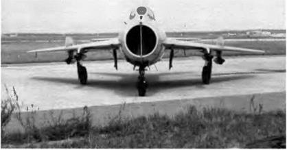
Category Mig

MiG-23 Series

The MiG OKB’s first approach to the variable geometry (VG) wing concept dates back to the early 1960s. The countless computations made by the design office showed that VG aircraft could offer an appreciable number of advantages. Many models were built and test­ed in TsAGI wind tunnels under different flight conditions: takeoffs, landings, and transonic/supersonic speeds. The tests confirmed most of the computations

One of the basic problems the ОКБ had to face in the field of struc­ture as well as aerodynamics was finding just the right place for the wing pivot, and thereby determining the chord and span of the wing. That problem was linked to the optimum pitching stability margin nec­essary according to the chosen sweep angle, since the shape of the wing as it pivoted and the mean aerodynamic chord were basically dependent on the position of the wing pivot. Another important item involved choosing the proper shape for the fixed wing panels (or gloves) and their wing-to-fuselage junctions. The difficulty there was linked to the distinctive features of the airflow around both the wing and the whole aircraft at great angles of attack in subsonic flight. The shape of the wing’s fixed panels and the blending of their leading edge into the fuselage act extensively upon the vortex flow in these flight conditions; and obviously the vortex flow influences the lift capability and the static pitching stability.

The third hurdle was developing a flight control system capable of changing the wing’s sweep angle and actuating an all-moving stabilator that operated differentially (taileron) plus all the moving surfaces hinged on the wing’s main panels (spoilers and full-span trailing edge flaps). The spoilers were highly efficient at minimum sweep angles, but this efficiency dropped abruptly once the wing was set for a high sweep angle in subsonic flight regime In transonic flight conditions, due to the airflow downwash onto the stabilator caused by their deploy­ment, the spoilers experienced reverse aerodynamic feedback. This is why the roll control had two functions. When the pilot pushed the con­trol column sideways, the spoiler on that side was extended and the opposite half part of the stabilator was deflected.

The spoilers’ extension angle was greatest for the smallest wing sweep angle; as the sweep angle increased, the angle of the spoilers decreased all the way to zero. The slab stabilator operating differential­ly thus functioned in place of the aileron. To save weight and provide the yaw stability needed over its whole range of speeds, altitudes, and load factors, the aircraft was fitted with a large folding ventral fin (the first of its kind in the world)

Development of the MiG-23 was completed in record time by a group of highly motivated engineers who were never short of ideas, to judge from the number of patents registered as the prototype took shape. The MiG-23 silhouette emerged gradually. The OKB first built an aircraft of a totally different concept It had a fixed delta wing, and its power pack included two lift jets to shorten takeoffs and landings and a primary power plant fed by two lateral air intakes (the first of their kind for a supersonic mixed-power aircraft), clearing space in the nose for the radar. That aircraft was the 23-01. In the course of development, which started in 1964, OKB engineers quickly realized that the lift jets became dead loads after takeoff and that the 23-01 was an uneconomical proposition. When the aircraft was almost completed, Mikoyan grew doubtful about the rationality of the project. Those doubts served as food for thought and were based on several arguments:

— even if the 23-01 could make short landings of 300-350 m (985-1,150 feet), that is, two times less than average, there was always a chance that one or both of the lift jets could fail on final approach

—the space occupied by the lift jets could be better used to house fuel tanks to increase the aircraft’s range

The development of the 23-01 experimental machine was to some extent tied to the customs of the day. At about this time France flight – tested the Dassault Balzac experimental prototype powered by one cruising turbojet and six smaller lift jets. Other countries such as Great Britain and West Germany had also started to design similar machines. The fourteen flights of the 23-01 and the sad end of the Balzac con – finned the pointlessness of the formula.

So another approach was tried: an aircraft powered by a turbojet whose thrust could be vectored at takeoff, in flight, and at landing by swiveling nozzles. The best-known examples are the British Harrier VTOL aircraft and, in the USSR, the experimental Yak-36 and Yak-38 carrier-based combat aircraft, which features both vectored-thrust engines and lift jets—but let us return to variable geometry. The final parameters selected for the wing were minimum sweep angle of 16 degrees, maximum sweep angle of 72 degrees, and leading edge flaps. The advantages of those choices are twofold.

1. Airflow characteristics: high lift-to-drag ratio in supersonic flight conditions due to a high sweep angle and a low thickness-chord ratio and in subsonic flight conditions due to a low sweep angle and a high wing aspect ratio; excellent lift coefficient at takeoff and landing because of a high aspect ratio and the full-span lead­ing edge and trailing edge flaps, good lift-to-drag ratio and lift coefficient at transonic speeds with a midrange sweep angle

2. Flight data: better performance due to peak application of the sweep angle. On that subject it should be noted that the MiG-23 pilot could choose any sweep angle between 16 and 72 degrees, each one presented a distinct advantage for a particular flight regime. Practical experience showed that the three most popular sweep angles were 16, 45, and 72 degrees. Because of its wide – ranging flight envelope, the MiG-23 was undoubtedly one of the best frontline fighters of the 1970s.

As soon as development was halted on the 23-01 VTOL, the highest priority was assigned to the 23-11 VG project. This was further boosted in 1965 by a decree of the ministry of aircraft production that detailed the main specifications: "The MiG OKB is commissioned to design and build a second prototype of the MiG-23 [the first was the 23-01] fitted with a high-lift variable geometry wing. The Rodina MKB [headed by general designer Selivanov] is in charge of designing the wing pivot." The preliminary design was drawn up in a very short time, from Janu­ary to March 1966. A. A. Andreyev, a very capable designer, was put in charge of the project’s technical management.

The R-27 turbojet was developed especially for the MiG-23 at a time when it was unclear whether the 23-01 or the 23-11 would win out. This is why it was developed and tested concurrently with the two aircraft. It was designed by K. R. Khachaturov as a modification of the R-11F2S-300 twin-spool turbojet, a reliable engine that had powered many of the MiG-21 variants and the whole Yak-28 line.

In the MiG-23 development process care was exercised to auto­mate as many of the pilot’s tasks as possible, especially while intercept­ing. A. V. Fedotov, newly appointed as the OKB’s chief test pilot, played a dominant part in developing those systems. The 23-11 went for its first flight on 10 April 1967 with this experienced pilot at the con­trols and the wing at 16 degrees. As early as the second flight two days later, he tested the whole range of sweep angles. The aircraft proved to be easy to control whatever the sweep angle, a quality that triggered Fedotov’s enthusiasm. His log entry for that day reads: "Flight with 16 to 72” sweep angle. It’s a first! Terrific!"

That kind of emotional report seldom appears in a test pilot’s log­book, but admittedly this was a rather unusual case. As early as the third flight, Fedotov broke the sound barrier and continued to acceler­ate until he reached Mach 1.2 with a 72-degree sweep angle. A few weeks later, on 9 July 1967, the MiG-23 made its public debut with Fedotov at the controls. It was clear after this brilliant display that the 23-11 would be the originator of a great aircraft family—and that was the case, even though the entry into service of such a new aircraft caused some problems of familiarization for pilots (before the delivery of a two-seat trainer to the fighter regiments) and field support crews.

The variable geometry concept was at the heart of some structural innovations. The fuselage structure was organized so that fuel tank no. 2 and the wing center section were as one. It was constructed of weld­ed thin panels made out of VNS-2 alloy. This fuel tank was in fact the aircraft’s primary structure. The stressed box that upheld the wing piv­ots was attached to that structure, and the air intake duct passed through it. This “wing box-tank” sustained high stress loads at all times and especially during high-g maneuvers. Considering the peculiarity of the aircraft’s missions, the breaking strength of this structure was com­puted to withstand limit load factors up to 8.

During the factory experiments, state acceptance trials, and mili­tary tests, fuel tank no. 2 never caused trouble. And yet. . On 14

March 1972 test pilot A. G. Fastovets had to check the strength of a new type of wing that had a larger area (called the type 2 wing); to do that, he had to reach the limit load factor in pulling out of a long dive. Just as he hit 7.3 g on the accelerometer at 1,000 m (3,280 feet) the tank gave way, and the aircraft totally disintegrated. The pilot was lucky to eject in time.

The subsequent investigation blamed the failure of this primary structural element on cracks that had formed in the panels due to some sort of soot by hydrogen molecules that had found its way onto some of the rough castings. The production factory had to revise the whole of its welding process for the components of fuel tank no. 2 and to inspect all tanks already built. Several cases were reported of wing pivot failure due to the infiltration of hydrogen molecules in welded parts and rotating shafts as well. That problem was overcome by increasing the number of quality checks at every stage of manufacture and by strengthening the structure of the no. 2 fuel tank for all aircraft on the assembly line. For the aircraft already completed, heat carefully applied to the tank structure prevented the hydrogen molecules from spreading and the stresses from accumulating. Moreover, the pivot rotating shafts were made out of a better steel alloy called khromansil.

The area of the type 2 wing was augmented by a chord increase on the leading edge, but it had no leading edge flaps and had been dubbed the "dog-toothed" wing because of the typical shape of the end of its inner leading edge. This enlargement—5.25 m2 (56.51 square feet) at 16 degrees, 4.27 m2 (45.96 square feet) at 72 degrees—resulted in a sweep angle increase at the leading edge. The three most popular angles— 16°, 45°, and 72”—thus became 18”40′, 47°40′, and 74 40’, a constant difference of 2° 40’. But for convenience’s sake it was decided not to modify the figures in the flight manual or on the instrument panel’s sweep angle indicator, which therefore provided erroneous readings.

This enlarged wing would later be fitted with leading edge flaps and named the type 3 wing. The first MiG-23s equipped with that wing appeared in 1973, and from that date all MiG-23s and MiG-27s used it until assembly lines were closed in the early 1980s. The hydraulically driven flaps were added to raise the lift coefficient at great angles of attack. After the basic causes of flow breakaway (resulting in a severe buffeting) were suppressed, it became possible to fly at even greater AOAs. After a great deal of research, engineers developed an automat­ed contrivance to protect against engine surges and flameouts while missiles and cannons were fired.

The more the aircraft was developed, the more the OKB and its client—the air force of the Soviet Army (WS SA)—realized that it had to be upgraded. Its stability, handling characteristics, and maneuver­ability were significantly improved. It was possible to raise the maxi-

mum operating limit load factor not only by making the airframe stur­dier but also by using sweep angle variations intelligently during high-g maneuvers.

The aircraft’s handling characteristics at great AOAs were improved, the pilot helped by new visual and tactile warnings of criti­cal AOAs that could prompt spins. Moreover, the sighting system was improved and the radar was modified so that it could operate in the close-combat mode; simultaneously, the aircraft received a target illu­minator to guide semiactive radar homing missiles. New air-to-air mis­siles optimized for close combat were tested and certified.

In the 1970s a prolific family of attack airplanes based on the MiG – 23 airframe developed. They could cany either bombs or rocket pods, air-to-surface missiles, six-barrel 30-mm guns, and many other front­line air support weapons. With every modification the MiG-23 became lighter. For instance, the takeoff weight of the MiG-23M (1971) was 15,750 kg (34,715 pounds), while for the MiG-23ML (1976) the compa­rable figure was 14,500 kg (31,960 pounds).

The rapid pace of advances in electronics and optoelectronics made it possible to produce new types of sensors related to outward sight, detection, IFF capabilities, computation of target coordinates, and the like. The power and capacity of the Sapfir radar improved sig­nificantly, and ground clutter was cleaned up. The radar was given new operating modes: separation of mobile targets in the lower sector, automatic and simultaneous tracking of several targets, and detection of small ground targets. The MiG-23P’s automatic flight control system (SAU) featured a digital computer unit to control the aircraft’s flight path.

MiG-23s were mass-produced in many versions until the early 1980s and are still operated in many countries, including Russia and the other republics. Today it is widely recognized that the MiG-23 rep­resented an important step in the development of fighter and tactical air command in the USSR.

MiG 25PD SL

Experience acquired with the MiG-25PD and PDS interception ver­sions demonstrated that the aircraft could be operated at low and medium altitudes provided that they could be equipped with active jammers and IR countermeasures One aircraft was modified and referred to as the MiG-23PD SL but did not go beyond the prototype stage.

1D1IW Multirole Twin-Engine Aircraft

This lightweight twin-engine was designed to carry passengers or cargo to and from any unpaved strip 400 m (1,300 feet) long and having a minimum strength of 5 kg/cm2 (71.1 pounds per square inch). The air­craft was intended for around-the-clock, all-weather use. Its APU sup­plies the necessary power for all loading and unloading operations.

Its power unit—two TV7-117 turboprops rated individually at 1,840 kw (2,500 ch-e)—and fuel system were specially designed to allow a limited use of diesel oil. The engines drive reversible-pitch propellers. The aircraft can fly and land with one engine inoperative, and it can be equipped with floats or skis. The twin-boom architecture with a high – set tailplane was used for ease of entry to the rear fuselage; the rear end opens upward, clearing the way for direct access to the cargo hold: length, 4 m (13 feet, 5.4 inches); width, 1.48 m (4 feet, 10.3 inches); height, 1.6 m (5 feet, 3 inches); volume, 6 m;i (211.89 cubic feet). At 1.5 m (4 feet, 11.1 inches), the sill height of this hold permits direct trans­fers to and from truck beds. All other loading problems are handled by the integral ceiling hoist.

The 101M was created to handle five basic missions:

—transport of field hospitals that can be set up quickly in case of emergency (disasters, accidents, epidemics)

—evacuation of casualties and the critically ill

—transport of supplies, medicines, and relief workers in the affected areas

—transport of geological expeditions and the like to remote or inac­cessible locales —forest fire extinguishment

To fulfill its purpose, the aircraft could carry a variety of loads:

—everything required for a complete airmobile field hospital in eight containers attached to the underwing store stations, plus the nec­essary medical staff (ten to twelve persons); total weight, 2,000 kg (4,400 pounds)

—eight to twelve sick or wounded persons on stretchers, plus the medical assistant; medical personnel, survivors, badly burned per­sons, and the like; total weight, 1,000 kg (2,200 pounds)

—various other loads, solid or liquid

Loading a stretcher holder with a ceiling hoist. (A) Electrical hoist on rail. (B) Stretcher holder (two or three persons).

For the first layout, the following setup times were planned: 30 minutes to install the eight containers; 15 minutes for aircraft turn­around; 10 minutes for a quick change of the cabin layout to evacuate wounded persons; 10 minutes for a quick change of the cabin layout to transport loads; and 15 minutes to load eight wounded persons on stretchers.

The airmobile field hospital created for this aircraft includes:

—four inflatable-frame tents at 50 m2 (538.2 square feet) apiece —four electronic monitors, surgical instruments, stretchers, oxygen tanks, and other medical equipment —the emergency power unit that burns kerosene out of the aircraft’s supply to provide the necessary overpressure, lights, and climate controls in the tents

—eight to twelve stretchers, monitors with the appropriate connec­tions for the stretchers, anesthetics, various life-support devices, and other evacuation materiel

The tents, medical equipment, and emergency power unit (but not the monitors or the stretchers) are carried in eight standardized con­tainers set in pairs under four wing store stations. Those containers can be either lifted or transported on wheels. The field hospital and all of its equipment weighs 1,200 kg (2,645 pounds) and takes up 200 m2 (2,150 square feet). The first tent can be erected in fifteen minutes; and it takes one and one-half hours to set up the entire hospital, which can be heated or cooled to a constant 22° C (plus or minus 5° C). The hos­pital is self-sufficient between five and six days with six to eight med­ical attendants and four technicians.

Loading directly out of a truck bed.

Specifications

Span, 13.5 m (44 ft 3.5 in); overall length, 12.45 m (40 ft 10.2 in); height, 4.4 m (14 ft 5.2 in); wing area, 33.53 m2 (360.92 sq ft); takeoff weight with 2,000-kg (4,400-lb) payload, 9,000 kg (19,835 lb); max pay – load, 4,000 kg (8,800 lb); max fuel, 2,000 kg (4,400 lb).

Design Performance

Economical cruising speed for range of 2,700 km (1,680 mi), 530 km/h at 11,800 m (286 kt at 38,800 ft); economical cruising speed for range of 1,300 km (810 mi), 530 km/h at 200 m (286 kt at 650 ft); max cruis­ing speed for range of 1,800 km (1,120 mi), 670 km/h at 7,000 m (362 kt at 22,960 ft); takeoff/landing roll, 150-200 m (490-655 ft).

UTI MiG-9 / I-301T / m

As mentioned above, the need to train pilots for the MiG-9 forced the OKB to design a two-seat version of the aircraft. An UTI MiG-9 (Ucheb no-trenirovochniy istrebityel: fighter-trainer) became a priority as soon as the WS adopted the single-seater—there was no other dedicated air­craft available.

Design of the two-seater MiG-9 was started at the OKB during the summer of 1946, and on 30 October the preliminary design was agreed upon. It was a tandem two-seater, and to make room for the

image89

The earliest Soviet ejection seats, developed by MiG, were tested on the FT-2 by the use of mannequins at first.

second seat in the airframe one of the two fuel tanks in the fuselage had to be removed and the capacity of the other one had to be reduced by one-third.

The front student-pilot cockpit and the rear instructor cockpit were separate and had their own sliding canopies. The aircraft had dual controls, and the instructor could use an intercom system to communicate with the student The I-301T no. 01 (or FT-1) was assembled with two German BMW 003 engines, a German K-2000 generator, and the wheels and shimmy-damper of an American Bell P-63 Kingcobra fighter.

The first ejection seats developed by the MiG ОКБ were due to be installed in this prototype. An emergency escape was supposed to work this way: (1) front canopy jettisoned, (2) rear canopy jettisoned, (3) rear pilot ejected, and (4) front pilot ejected. The prototype was also equipped with a new instrument, a Mach indicator (also called a Mach – meter). The two-seater had the same armament as the single-seater: one N-37 cannon whose muzzle was 1 16 m (3 feet, 4.6 inches) away from the engine air intake, and two NS-23 cannons whose muzzles were 0.5 m (1 foot, 7.7 inches) away from that spot.

The FT-1 left the factory in June 1947 and was flown by Gallai in July. In August it underwent its certification tests but failed because of the restricted view from the instructor’s cockpit in the rear. The air­craft could not meet the requirement for which it was designed, pilot training. The prototype was later used for improving various MiG-9 sys­tems and developing underwing fuel tanks.

Specifications

Span, 10 m (32 ft 9.7 in); length, 9.83 m (32 ft 3 in); height, 3.225 m (10 ft 6.7 in); wheel track, 1.95 m (6 ft 4.8 in); wheel base, 3.072 m (10 ft 0.9 in); wing area, 18.2 m2 (195.9 sq ft); empty weight, 3,584 kg (7,900 lb); takeoff weight, 4,762 kg (10,495 lb); fuel, 840 kg (1,851 lb); oil, 35 kg (77 lb); gas, 7 kg (15.5 lb); wing loading, 261.7 kg/m2 (53.6 lb/sq ft).

Performance

Max speed, 900 km/h at 4,500 m (486 kt at 14,760 ft); max ground speed, 830 km/h (448 kt); climb to 5,000 m (16,400 ft) in 5 min; to 10,000 m (32,800 ft) in 10 min; service ceiling, 12,500 m (41,000 ft); landing speed, 190 km/h (103 kt); endurance, 50 min; landing roll, 780 m (2,560 ft).

MiG-15 / SU

From the inception of fighter aircraft in World War I, pilots aimed at objects in the air or on the ground by pointing the aircraft so that the target appeared in the gunsight’s cross hairs. The fighter’s armament

image130

The MiG-15 no. 935 was modified to be equipped with an experimental weapons sys­tem having a limited slew angle

was fixed, making it difficult to direct (especially at high speed). Pilots had little time to aim and fire at their targets.

This is why aircraft manufacturers and armament specialists joined forces to develop rotating gun systems to simplify aiming and firing sequences for the fighter pilot and thereby to guarantee a deci­sive tactical advantage in dogfights. In late 1949 OKB engineers and armament experts decided to design an experimental weapon system with a limited slew angle and to test it on a MiG-15. It was one of the very first installations of the kind in the USSR.

First, cannons of a new type —23-mm Shpitalniy Sh-3s—were installed in a MiG-15 bis (ISh). They had standard mountings and passed their firing tests. On 14 September 1950 the council of ministers ordered MiG-15 no. 109035, built in factory no. 1 at Kuybyshev, to be sent to the OKB’s experimental workshop and equipped with the limit­ed slew angle V-l-25-Sh-3 weapon system, which consisted of two experimental 23-mm Sh-3 short-tube cannons with 115 rpg. The specifi­cation called for the weapons to rotate in the vertical plane (11 degrees upward, 7 degrees downward) concurrently with a synchronous dis­placement of the gunsight in the cockpit. The aim of the cannons was remotely controlled by two switch knobs—one on the throttle (RUD) and one on the stick (RUS) Either knob could be used.

image131

A front view of the V-l-25-Sh-3 weapons system with its two 23-mm Sh-3 cannons.

The specifications and performance of the SU were virtually identi­cal to those of the MiG-15 with the RD-45F engine. The MiG-15 (SU) no. 109035 was tested by Yu A. Antipov and sent to the Nil WS on 20 June 1951 for state trials, which took place from 30 June to 10 August. The aircraft was put through its paces by military test pilots such as Trofimov, Makhalin, Dzyuba, Lukin, Kotlov, Tupitsin, and Filippov. They made sixty-three flights with a total of forty-two hours and forty – six minutes of flying time. The rotating elements of the new weapon system functioned for fifty-two hours, with the cannon pivoting for six and one-half hours

Firing tests in flight gave prominence to the tactical advantages of the SU over the production MiG-15, but these advantages were tem­pered by the relatively small angular movement of the cannons and by the limited possibilities of the ASP-3N production gunsight. Combat simulations were staged against an 11-28 and a MiG-15 bis. These proved that the V-l-25-Sh-3 could widen the possibilities of head-on attacks without a risk of collision. At a distance of 800 m (2,600 feet) and identical load factor for both the target and the attacker, the SU could fire at a heading angle 7 to 13 degrees wider than that of a con­ventionally armed Fighter. The pivoting Sh-3 also made possible a much longer burst. The trial attacks on the 11-28 were launched from the rear from quadrants two and three, while the combat with the MiG – 15 bis took place at 15,000 m (49,200 feet).

Tests showed that fifteen to twenty flights were sufficient to train pilots to operate the new system; compared to the three-cannon stan­dard armament, the new layout was more straightforward. In-flight exercises also demonstrated that firing at extreme slew angles did not affect the aircraft’s speed and trim at 5,000 m (16,400 feet) but did

image132

Close up of one of the two Sh-3 cannons, which rotated only in the vertical plane between +11 and -7 degrees

detract from the lateral stability somewhat Moreover, because of a minor buffeting produced by rudder deflection, undamped oscillations were generated at Mach 0.845 on the longitudinal and vertical axes. The aircraft’s ground handling deteriorated because of the much larger turning radius entailed by the V-l-25-Sh-3 installation. Its ranging dis­play system also proved to be too slow.

These first tests with limited slew angle cannons proved that it was essential to widen the angles—to 25-30 degrees upward and 10-15 degrees downward—and to use an automatic gunsight. A mobile gun – sight was tested on the experimental MiG-15 to assess its simplicity of operation. Another attempt of this kind was made in 1953-54 with the SN, an experimental member of the MiG-17 family.

image133

The two drop tanks of the MiG-15 bis—capacity 250 1 (66 US gallons)—were braced.

MiG-17PF / SP-7F

The purpose of this project was to combine the combat resources of the MiG-17P and the MiG-17F into a single aircraft (hence the equa­tion MiG-17P + MiG-17F = MiG-17PF). Rolled out in 1952, the MiG – 17PF marked a new stage in the history of the MiG-17. It was powered by the same engine as the MiG-17F, a VK-1F rated at 2,595 daN (2,650 kg st) dry thrust and 3,310 daN (3,380 kg st) reheated thrust. It carried three NR-23 cannons, just like the MiG-17P. Its fire control radar was the RP-1 Izumrud. But the plans for this aircraft contained a number of structural and equipment modifications:

—the armament array and other equipment in the nose of the fuse­lage were repositioned

—because of the size of the afterburner duct, the exhaust pipe had to be redesigned

—a cooling shroud was set between the aircraft’s skin and the after­burner to protect some structurally significant items (SSI) of the fuselage

—additional hydraulic actuators were added to the afterburner control

—the GSR-3000 generator was replaced by the more sophisticated GSR-6000

—early versions of a radar warning receiver (nicknamed Sirena-2) and a ground position indicator (NI-50B) were installed

In terms of performance, the MiG-17F and the MiG-17PF were vir­tually identical. Despite the added takeoff weight the MiG-17PF did not differ much from the basic model except for its 360-degree turn time, which rose to 85 seconds (62 seconds with reheat), and its climb rate, which dropped to 55 meters per second (10,800 feet per minute). The MiG-17PF served in PVO units for several years before a complete reappraisal of its armament was ordered. All cannons were then removed and replaced by four radar-guided air-to-air missiles, and the MiG-17PFU was born.

The MiG-17PF was built in Poland as the LIM-5P and in Czechoslo­vakia as the S-104.

Specifications

Span, 9.628 m (31 ft 7 in); length, 11.68 m (38 ft 3.9 in); height, 3.8 m (12 ft 5.6 in); wheel track, 3.849 m (12 ft 7.5 in); wheel base, 3.44 m (11 ft 3.4 in); wing area, 22.6 m2 (243.3 sq ft); empty weight, 4,150 kg (9,147 lb); takeoff weight, 5,620 kg (12,386 lb); max takeoff weight, 6,280 kg (13,841 lb); fuel, 1,143 kg (2,519 lb); wing loading, 245.6-277 9 kg/m2 (50.3-57 lb/sq ft).

Performance

Max speed, 1,121 km/h at 4,000 m (605 kt at 13,120 ft); initial climb rate, 55 m/sec (10,800 ft/min); climb to 5,000 m (16,400 ft) in 2.5 min; to 10,000 m (32,800 ft) in 4.5 min; takeoff roll with reheat, 600 m (1,970 ft), landing roll with flaps set at 60 degrees, 830 m (2,720 ft).

MiG 19P / SM12/3 / SM12/1 / SM12/2

Plans for the SM-12/3 originated in the PVO’s need for a fast, high-alti – tude interceptor. Compared with the MiG-19 prototype, the SM-12/3 had a longer forward fuselage and thinner rims around the engine air intake, which encircled a two-position nose dome housing the radar antenna. This arrangement was chosen to reduce the ram pressure losses in the intake. The AM-9B (RD-9B) turbojets were replaced by R3- 26s rated at 3,725 daN (3,825 kg st) and built by a subsidiaiy of the Mikulin OKB managed by V. N. Sorokin. This change of power unit forced engineers to modify the nozzle throats and to install new heat shields in the engine bay

Other modifications included: more reliable BU-13MSK and BU – 13MK servo-controls for the slab tailplane and ailerons; the new APS – 4MD electric stabilator trim actuator, cutting to a quarter the time required to set up the slab tailplane on the MiG-19S; and more unguid­ed rockets to offset removal of the NR-30 cannon from the fuselage. These and other changes greatly enhanced the performance of the SM – 12/3 over that of the MiG-19S. Maximum speed jumped from 1,430

image210

The SM-12/3 was a reengined MiG-19S whose forward fuselage was lengthened notice­ably. The two-position nose cone housed the radar.

km/h (772 kt) to 1,930 km/h (1,042 kt), and service ceiling improved from 17,500 m (57,400 feet) to 18,000 m (59,000 feet). The latter alti­tude could be reached in just 3.2 minutes. Thus a significant increase in speed and ceiling had been achieved without modifying the aircraft’s structure noticeably and increasing its weight or the thrust of its power unit appreciably.

Ye152A

The objective of this project was to develop a fighter capable of colli­sion-course interception at 2,000 km/h (1,080 kt) between 1,000 and

23,0 m (3,280 and 75,440 feet). This tailed delta aircraft was powered by a pair of R-11F-300 turbojets rated at 3,800 daN (3,880 kg st) and 5,625 daN (5,740 kg st) with afterburner; and it was to be equipped with the Uragan-5B radar, which was still untested because of the eigh­teen-month delay of the Ye-150’s engines.

The fixed cone was made of dielectric material to house the TsP radar antenna. Its triple-angle profile was selected to make the bow shock wave diverge. To control the flow in the air intake duct, the hydraulically controlled annular nose cowl moved on four tracks to three positions as dictated by the aircraft’s speed and subsequently by ram air pressure. The Ye-152A’s wing derived from the Ye-150. The fuselage was widened at the second spar level to accommodate two engines instead of one. The stabilator surfaces were identical to those of the Ye-150 except that their span was increased to 5.85 m (19 feet, 2.3 inches) from 5.292 m (17 feet, 4.3 inches) because of the wider fuse­lage. The Ye-152A had three airbrakes (one under the fuselage and two on its sides) and a double tail chute.

The twin-jet Ye-152A made its first flight before the Ye-150, which had to wait eighteen months for its engine

The fuel tanks—six in the fuselage, one between the wheel wells, and two in the wing) had a total capacity of 4,400 1 (1,162 US gallons). The aircraft could be armed with two K-9 air-to-air missiles developed by the MiG OKB (factory designation K-155). If the pilot had to eject he was protected by the cockpit hood, a precautionary measure that was used on other MiG fighters (including the MiG-21). Its mam systems included the RSIU-4V VHF, the ARK-54N automatic direction finder, the SRO-2 IFF transponder, and the Meteorit radio-nav station. The SRP computer and the AP-39 autopilot were linked to the TsP radar.

The aircraft was rolled out in June 1959 and first piloted by G. K. Mosolov on 10 July. Tests opened on 10 June and ended on 6 August 1960 after fifty-five flights—fifty-one with clean wings, two with pylons, and two with pylons and K-9 missiles. The highest speed reached with wing pylons came at 13,000 m (42,640 feet). Ten in-flight engine relights were carried out at altitudes between 6,000 and 10,500 m (19,680 and 34,440 feet). Each time, the engine relit on the first try and built up full power in fifteen to twenty-five seconds.

Specifications

Span, 8.488 m (27 ft 10.2 in); overall length, 19 m (62 ft 4 in); fuselage length (except cone), 15.45 m (50 ft 8.3 in); wheel track, 3.322 m (10 ft

The weapons system that combined the Uragan-5B radar and K-9 air-to-air missiles was tested on the Ye-152A.

10.8 in); wheel base, 5.995 m (19 ft 8 in); wing area, 34.02 m2 (366.2 sq ft); takeoff weight, 12,500 kg (27,550 lb); max takeoff weight, 13,960 kg (30,770 lb), fuel, 3,560 kg (7,845 lb); wing loading, 367.4-410.3 kg/m2 (75.3-84.1 lb/sq ft); operating limit load factor, 7.

Performance

Max speed, 2,135 km/h at 13,700 m (1,153 kt at 44,940 ft); 2,500 km/h at 20,000 m (1,350 kt at 65,600 ft); climb to 10,000 m (32,800 ft) in 1,45 min; to 20,000 m (65,600 ft) in 7,64 min; service ceiling, 19,800 m (64,950 ft); takeoff roll, 1,000 m (3,280 ft); landing roll, 1,600 m (5,250 ft).

IVIiG-21FL / Tip 77

This frontline fighter-interceptor was a special version of the MiG-21 PF developed to be built under license in India and for export. Externally both aircraft were very similar, but the MiG-21 FL had the same engine as the MiG-2 IF the R-l 1F-300—and the total capacity of the fuel tanks was increased to 2,900 1 (766 US gallons). Moreover, the RP-21 radar was replaced by the R-2L, a less advanced export model.

The MiG-21FL was built in the MMZ Znamya Truda factory in Moscow between 1965 and 1968 and by HAL in India from 1966 onward.

Specifications

Span, 7.154 m (23 ft 5.7 in); fuselage length (except cone), 12.285 m (40 ft 3.7 in); wheel track, 2.692 m (8 ft 10 in); wheel base, 4.806 m (15 ft 9.2 in), wing area, 23 m2 (247.6 sq ft), takeoff weight in clean config­uration, 7,830 kg (17,255 lb); max takeoff weight, 9,400 kg (20,715 lb); max takeoff weight on rough strip or metal-plank strip, 8,100 kg (17,850 lb); wing loading, 340.4-408.7-352.2 kg/m2 (69.8-83.8-72.2 lb/sq ft); max operating limit load factor, 8.

Performance

Max speed, 2,175 km/h at 13,000 m (1,175 kt at 42,640 ft); max speed at sea level, 1,130 km/h (610 kt); climb rate at sea level in clean confi – uration, 175 m/sec (34,450 ft/min); climb to 18,500 m (60,700 ft) in 8 min; service ceiling, 19,000 m (62,300 ft); landing speed, 280 km/h (151 kt); range, 1,450 km (900 mi); with 800-1 (211-US gal) drop tank, 1,800 km (1,120 mi); takeoff roll, 850 m (2,790 ft); landing roll with tail chute, 850 m (2,790 ft).

Ye-8

Work on the Ye-8 frontline fighter-interceptor got under way in 1961 by government decree. It was referred to as the MiG-23 (the second aircraft to go by that name). Basically it was a modified MiG-21 PF air­frame reengined with the more powerful R-21 turbojet and equipped with the new Sapfir-21 radar in the nose. The antenna diameter of this radar forced the manufacturer to move the air intake under the cock­pit. To simplify the mass production of the future MiG-23, which was intended to replace the MiG-21 PF on the assembly lines, the Ye-8 received the same on-board systems as the MiG-21. The Ye-8 require­ment called for a fighter capable of intercepting and destroying intrud­ers in the front and rear sectors twenty-four hours a day and in any weather conditions.

The production MiG-21 wing retained for both Ye-8 prototypes was not fitted with the SPS system of flap blowing, and the stabilator, also taken from the MiG-21 assembly line, was lowered by 135 millimeters (5.3 inches) below the fuselage datum line. Other noteworthy technical innovations were also made:

1. Under the tail of the fuselage there was a ventral fin that folded to starboard when the landing gear extended, the hinge control being slaved to the gear’s follow-up linkage. Tested for the first time on the Ye-8, this type of ventral fin was later included on the production MiG-23 (the one with a VG wing).

2. A foreplane—or more precisely a rotating delta canard surface— with a span of 2.6 m (8 feet, 5.4 inches) was set immediately behind the radome. This "destabilizing” surface was not con­trolled by the pilot. In subsonic flight it behaved like a weather­cock; at Mach 1 and beyond, it was mechanically set to a neutral position in relation to the aircraft’s datum line, modifying the aerodynamic center and reducing the margin of pitch stability (unnecessary at supersonic speeds).

The R-21F that powered the Ye-8 was in fact an R-11F modified by N Metskhvarishvili and rated at 4,605 daN (4,700 kg st) dry or 7,055 daN (7,200 kg st) with afterburner (an outstanding afterburning ratio of

53 percent). Compared to the R-11F, the R-21F had a diameter of 845 mm (33.26 inches) versus 772 mm (30.39 inches), a nozzle throat diam­eter of 987 mm (38.86 inches) versus 902 mm (35.51 inches), and a dry weight of 1,250 kg (2,755 pounds) versus 1,165 kg (2,568 pounds). The ventral air intake was divided into two ducts by a three-step splitter

The 81 or Ye-8/1 consisted of a MiG-21 PF airframe drastically modified to make room for the Sapfir-21 radar antenna.

that could be adjusted electrohydraulically. The front gear leg retracted into the splitter. The main gear, taken from a production MiG-21 of the Ye-7 type, was strong enough to withstand takeoffs and landings on rough strips. The flying controls and the hydraulic system were those of the MiG-21, except for devices linked to the canard surfaces and the folding ventral fin. The armament specified for the Ye-8 was two K-13 air-to-air missiles, but neither the missiles nor the radar were ever installed.

The Ye-8/1, which bore the marking "81" on the sides of its fuse­lage just under the cockpit, was moved to the test center on 5 March 1962. Its R-21F no. 21-205 turbojet was intended only for ground tests and was later replaced by the flight-cleared R-21F no. 21-106. The first flight, on 17 April 1962 with G. K. Mosolov at the controls, went off without incident. For the first five flights all systems were tested, the engine was put through its paces (including relight in flight at up to 8,000 m [26,240 feet]), and the directional stability was controlled. The next six flights were dedicated to measuring accelerations at various Mach numbers and reaching the service ceiling. The operation of the canard surface was checked at the same time.

After one engine surge and one flameout on the twenty-first and twenty-fifth flights, the R-21F no. 21-106 was replaced by no. 21-108, an

The 82 or Ye-8/2, here armed with K-13 missiles, was flown only thirteen times before its tests were halted

engine with a larger turbine nozzle. On 11 September 1962 the engine burst at Mach 1 7 at 10 000 m (32,800 feet). Mosolov ejected but was seriously wounded and bad to be taken to a hospital.

The Ye-8/2 (or "82”) was flight-tested thirteen times by A V Fedo­tov from 29 June to 4 September 1962. But all flights were canceled after the Ye-8/1 crash. The inquiry revealed that the accident was due to the breakup of a part of the sixth compressor stage rotor. Once it came loose it ripped through the engine casing and the aircraft’s skin and hit the wing, demolishing the aileron. The plane entered a tailspin at 5,000 m (16,400 feet). The sudden loss of thrust led to a surge in the compressor and the air intake ducts During the subsequent rapid deceleration the aircraft suffered severe lateral oscillations, a phenom­enon observed in previous flights after the pilot had intentionally cut off the engine At this point the aircraft was practically uncontrollable.

Specifications

Span, 7 154 m (23 ft 5.7 in); length (except probe), 14.9 m (48 ft 10.6 in); wheel track, 2.787 m (9 ft 1.7 in); wheel base, 3.35 m (10 ft 11.9 in); wing area, 23.13 m2 (249 sq ft), takeoff weight, 6,800 kg (14,985 lb);

max takeoff weight, 8,200 kg (18,070 lb), wmg loading, 294-354.5 m2 (60.3-72.7 lb/sq ft).

Performance

Max speed, 2,230 km/h (1,204 kt); service ceiling, 20,000 m (65,600 ft).

IVHG-23PD / 23-01

This aircraft represented one-half of a dichotomous attack to a single objective. The specifications for the 23-01—as well as for the 23-11 or MiG-23PD (as for the MiG-21 PD, Podyomnye Dvigatyeli = lift jet), built simultaneously—called for the aircraft to be capable of speeds of Mach 2-2.3 and also offer STOL performance.

The preliminaiy designs were completed in 1964, and assembly of the prototype started in 1965. V. A. Mikoyan (son of the president of

The STOL variant with lift jets was one of the innovations explored with the 23-01.

the Supreme Soviet and nephew of A. I. Mikoyan) was commissioned to take care of both projects. For the 23-01 the design bureau chose the tailed delta configuration of the MiG-21. The midwing was an enlarged replica of that of the MiG-21. The horizontal tail surfaces were of the all-flying type (slab tailplane). Because the concept selected for this prototype was based on the employment of lift jets, the primary turbo­jet could be fed only by semicircular lateral air intakes with shock cones identical to those of the French Mirage III. Both air ducts were separated slightly from the fuselage near the air intakes to create boundary layer bleeds, and both had blow-in doors above the wing’s leading edge.

The two Kolyesov RD-36-35 lift jets rated at 2,300 daN (2,350 kg st) apiece were set in the middle of the fuselage with a slight forward incli­nation. They operated only during takeoffs and landings. For those short periods, a rearward-hinged, louvered door was opened by an actuator to supply air to the lift jets. Under the fuselage, both nozzle throats were fitted with a rotating grid that allowed the pilot to alter the direction of the thrust vector. In a way they operated as thrust reversers at landing; on the other hand, at takeoff the thrust of the lift jets was added to that of the whole power unit. The primary power plant was the R-27-300 rated at 5,095 daN (5,200 kg st) dry or 7,645 daN

Moving the air intakes to the side made room for a radar unit aboard the 23-01, here armed with R-23R and R-23T air-to-air missiles

The 23-01 on final approach, with flaps fully extended The louvered door that feeds the lift jets is open.

354

The tail chute was one of several devices employed to shorten the landing roll.

(7,800 kg st) with afterburner. Like most of the MiG-21 variants the 23- 01 had the SPS system (flap blowing by air bleed downstream from the last compressor stage of the R-27-300). The canister for the cruciform tail chute was located at the base of the tail fin’s trailing edge.

Armament consisted of one twin-barrel GSh-23 under the fuselage and two air-to-air K-23 missiles under the wing (one K-23R and one K – 23T). The 23-01 was first piloted on 3 April 1967 by P. M. Ostapyenko who then took part in a series of complicated flight tests administered by V. M. Timofeyev In three months Ostapyenko acquired sufficient experience with this machine to fly it in the air display planned for 9 July 1967 at Domodyedovo to celebrate the fiftieth anniversary of the October Revolution Another ОКБ pilot, A. V. Fedotov, also flight-tested the 23-01; but this prototype had a very short life. Once the bureau’s focus shifted to the variable geometry wing, the 23-01 tests were termi­nated—immediately after Ostapyenko’s flyover at Domodyedovo— even though the aircraft’s flight envelope was left practically unex­plored with the exception of the takeoff and landing performance.

Specifications

Span, 7.72 m (25 ft 3.9 in); length (except probe), 16.8 m (55 ft 1.4 in), fuselage length (except probe), 15.995 m (52 ft 5 7 in); height, 5.15 m (16 ft 10.7 in); wheel track, 3.46 m (11 ft 4.2 in); wheel base, 6.13 m (20 ft 1.3 in); wing area, 40 m2 (430.56 sq ft); takeoff weight, 16,000 kg (35,265 lb); war load, 2,500 kg (5,510 lb); max takeoff weight, 18,500 kg (40,775 lb).

Performance

Takeoff roll with SPS and lift jets in clean configuration, 180-200 m (590-655 ft); landing roll with SPS, lift jets, and tail chute, 250 m (820 ft).