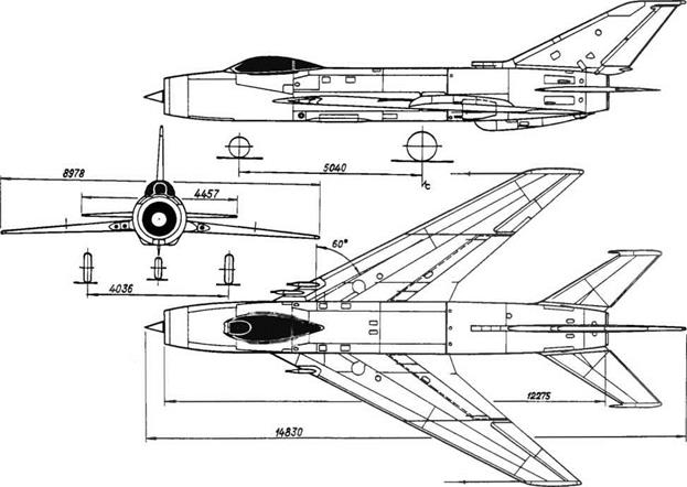
Toward the end of the 1940s a specification was laid down calling for a cover interceptor, a fighter whose role would be to oppose any invading aircraft as far as possible from its target and under any weather conditions. Several manufacturers put in a tender for the program:
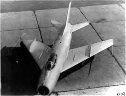
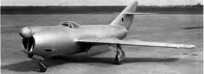
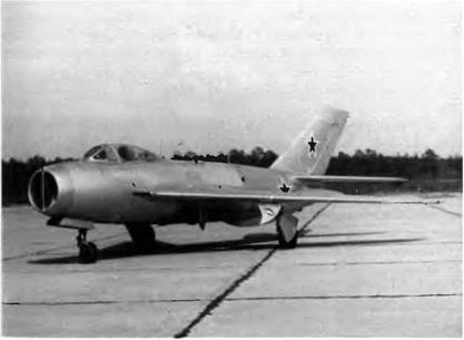
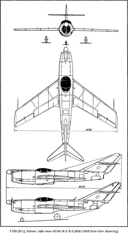
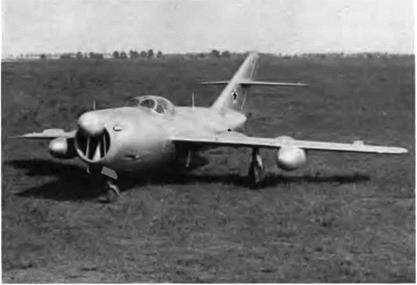
The 1-320 (R-1) was designed for the cover-interceptor mission and was powered by two RD-45F engines.
Sukhoi, Mikoyan, Lavochkin, and (later) Yakovlev. This is how a number of famous aircraft were created, including the Su-15 (the first of two), La-200, and La-200B. In this instance the result was the 1-320, an all-weather fighter proposed and built by Mikoyan in 1949.
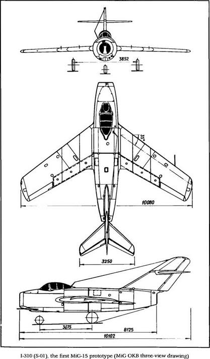
This twin-jet had a cantilever midwing with a 40-degree sweep angle at the leading edge, and its tail unit was also swept back. Because this aircraft was designed at the same time as the MiG-15 and MiG-17, the family resemblance will come as no surprise. However, the 1-320 outdid both of them in size as well as weight. It differed from them in its side-by-side cockpit layout (one captain and one pilot/radar operator) and its unusual power plant arrangement (two tandem-mounted turbojets in the fuselage). Its fuselage was 1.9 m (6 feet, 2.8 inches) in diameter with a maximum cross section of 2.83 m2 (30.4 square feet) The crew had dual controls and was equipped with two radar scopes. This certainly made the pilot’s job easier in combat, since the second crew member could scan the invaders or even fly the aircraft during the long defensive patrol flights. Each pilot had his own oxygen supply, and the overall reserve amounted to 6 1 (1.6 US gallons).
Both bladder fuel tanks—capacities 1,670 1 (441 US gallons) and 1,6301 (430 US gallons)—were placed behind the cockpit. The rear tank included a 45-1 (12-US gallon) antigravity feeder tank that supplied fuel
The R-l had two tandem-mounted turbojets. The front engine’s exhaust nozzle emerged from the underside of the fuselage, while the rear engine’s nozzle came out under the tail.
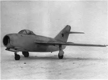
The R-2 differed from the R-l by its engines—two VK-1 turbojets—and its strengthened armament.
|
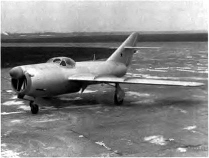
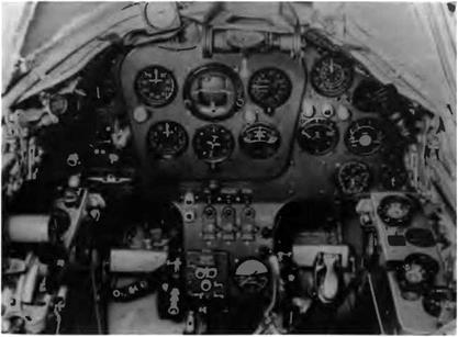
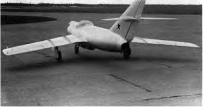
The R-2 cockpit canopy was deeper than that of the R-l.
|
to the engines during inverted flights. It was also planned to equip the aircraft with two 750-1 (198-US gallon) drop tanks beneath the wings.
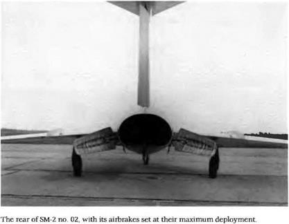
The front engine was located beneath the crew compartment, its exhaust nozzle emerging from the underside of the fuselage. The other engine was placed in the conventional position at the rear of the fuselage, its straight exhaust nozzle emerging from under the fin. The airbrakes flanked the tail section (area per unit, 1.08 m2 [11.6 square feet]; maximum deployment angle, 45 degrees).
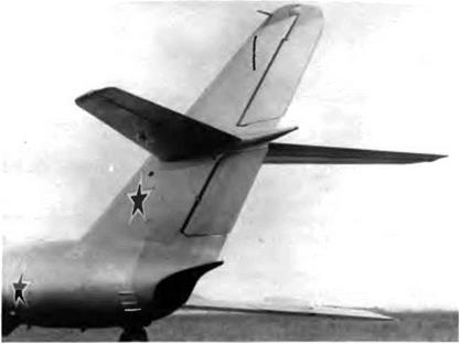
The trailing edge of the wing was fully occupied in the inner section by Fowler flaps designed by TsAGI (span, 3.18 m [10 feet, 5.2 inches]; area per unit, 3.1 m2 [33.4 square feet]; takeoff setting, 22 degrees; landing setting, 56 degrees) and in the outer section by internally balanced ailerons (span, 2.497 m [8 feet, 2.3 inches]; area per unit, 1.47 m2 [15.8 square feet]). Both R-l and R-2 prototypes had four fences on the upper surface of the wing. To compensate for the retroaction of the rudder and the transverse instability it caused, 900-mm (2-foot, 11.5- mch) spoilers were installed on the wing’s lower surface. Operated by electric actuators, they could be extended 40 millimeters downward. Spoiler extension was automatic whenever the rudder deflection exceeded 2 degrees. The stabilizer had a sweep angle of 40 degrees at the leading edge, while the tail fin had a sweep angle of 59 degrees, 27
|
|
minutes at the leading edge. The maximum deflection angle of the elevator was 33 degrees upward and 17 degrees downward. The maximum deflection angle of the rudder was plus or minus 24 degrees, 48 minutes.
The tricycle landing gear was hydraulically controlled, with air – and-oil shock absorbers on the legs of the main gear. They retracted into the wing, and their wheels were fitted with double brake shoes and 900 x 275 tires. The front leg and its wheel (520 x 240 tires, no brakes) retracted forward. The wheel doors, flaps, airbrakes, and booster cylinders for the aileron and the elevator were also hydraulically controlled. The hydraulic reservoir had a capacity of 35 1 (9 US gallons). The dual pneumatic system consisted of a main circuit that controlled the wheel brakes and the cannon loading plus a standby system that governed the gear, flaps, and wheel brakes Fire control was electrical, activated by one button on the captain’s stick.
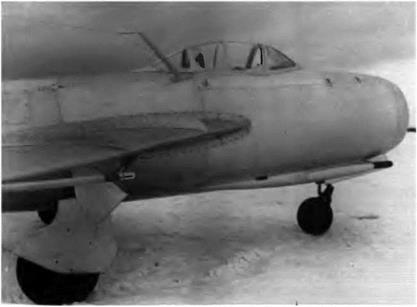
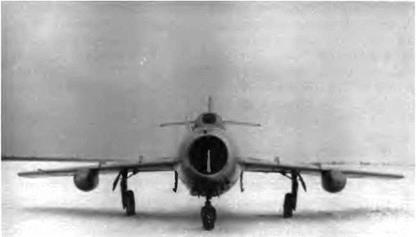
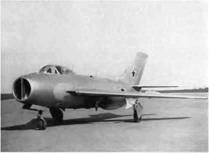
The first prototype, or R-l, was powered with two 2,225-daN (2,270- kg st) RD-45F turbojets. The R-2 and R-3 (in fact, a modified R-2) featured 2,645-daN (2,700-kg st) VK-1 turbojets. The air intake was divided into three ducts: the one in the middle fed the front jet, and the other two channeled air to the rear jet The 1-320 could fly and even take off on either of its two engines. The polystyrene dome that housed the Toriy-A radar designed by A В Slepushkin was located in the upper lip of the air intake. The armament comprised two N-37 cannons flanking the air intake.
The R-l was rolled out in April 1949 and made its first flight on 16 April with Ya I Vernikov and S Amet-Khan at the controls. Factoiy tests continued until 18 January 1950 under two pilots, A N. Cher – noburov and 1. Y Ivashchenko. The R-l was also flown by four LII pilots—Ya. I. Vernikov, S. Amet-Khan, S. N. Anokhin, and M. L. Gal – lai—and by pilots of the PVO, a potential customer. Lt. Gen. Ye. Ya. Savitskiy, commanding officer of the PVO’s fighter regiments, made the following comments after flying the 1-320 ‘The aircraft handles well at takeoff, in flight, and while landing. It has no tendencies to yawing or swinging. Being easy to handle, it can be flown by average pilots." The official test report added:
The aircraft has excellent in-flight steadiness on its three axes. Given the aircraft’s layout and the location of its fuel tanks, there is no need to use the elevator’s tab in a flight envelope ranging from takeoff speed to 700 km/h [378 kt]. Gear extension and retraction do not modify the aircraft trim. When performing a tight turn or a combat half-flick roll, the 1-320 handling characteristics remain safe. The airframe was initially stressed with a load factor of up to 5.9 for an aircraft weight of 8,530 kg [18,800
|
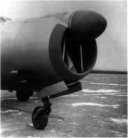
The R-2 radome, like that of the R-l, housed a Toriy-A radar. Note the partitions in the air intake, to supply air to both engines.
|
pounds]. The load factor was later increased to 8. To test the radar’s performance fourteen flights were carried out, nine of which involved targeting a Tu-2, an Li-2, a B-17, or a Tu-4. While trying to intercept a Boeing B-17 Flying Fortress, the 1-320 was caught in the propeller slipstream of the bomber, causing the fighter to make a spectacular pirouette.
Yu. A. Antipov, M. L. Gallai, N. P. Zakharov, and G. T. Beregovoy were four of the pilots who took part in the combat tests. The R-l was not certified because of its transverse instability in a narrow speed range between Mach 0.89 and 0.9, and also because of its wing dropping between 930 and 940 km/h (502 and 508 kt).
|

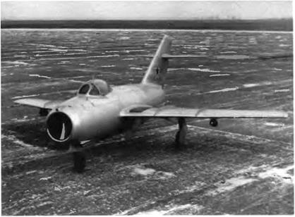
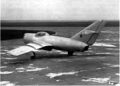
The 1-320 (R-2) was modified after an accident, becoming the R-3. Note the third wing fence.
|
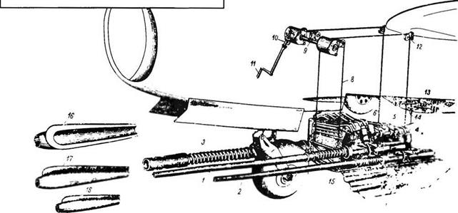
The VK-1 engine of the R-2 prototype boosted the maximum speed by only 3 percent—1,090 km/h (589 kt) IAS versus 1,040 km/h (562 kt) for the R-l —considering the severe limitations imposed by the stiffness problems of a thin, high-aspect-ratio swept wing. Except for its new engines, the R-2 was not greatly modified. The crew’s all-around visibility was improved, and the canopy was fitted with a more reliable emergency release system. The wing and the stabilizer were equipped with deicers, and the air intake ducts were electrically warmed. Its armament was supplemented by another cannon so that the prototype fielded a total of three N-37s, one on the left and two more on the right of the lower nose section.
The R-2 received its Toriy-A radar at the beginning of its test program. It was later replaced by a Korshun, also developed by Sle – pushkin. Neither radar was able to track targets automatically. The R-2 was equipped with an RV-2 radio-altimeter, an RSIU-6 VHF transceiver, and a Bariy (barium) IFF system.
This second prototype was rolled out in early November 1949. During its factory tests from December 1949 to September 1950 the aircraft made 100 flights, executed a steep spin, jettisoned its canopy in flight, performed several aerobatic maneuvers under negative gravity, flew at night, and dropped its auxiliary tanks. Between 13 and 30 March all test flights had to be suspended after a shell exploded in an ammunition belt and damaged the aircraft’s nose. The OKB took advantage of the repair time to make a few modifications. The wing anhedral was reduced to 1.5 degrees from 3 degrees, the span of the spoilers was increased to compensate for the transverse instability at high speeds,
|
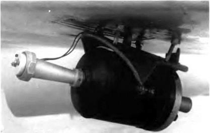
flipper tanks were tested on the 1-320 (R-3).
|
|
|
The exhaust nozzle breaches and fin of the R-2/R-3 were somewhat different from those of the R-l
|
|
an automatic airbrake deployment system was installed, and two fences were added on the upper surface of the wing. This repaired and modified R-2 became the R-3.
The first flight of the new version took place on 31 March. The test pilot noted that the wing anhedral modification had changed the transverse stability/yaw stability ratio. To deal with that problem a provisional ventral fin was added under the tail section. Moreover, the spoilers were mechanically linked to the ailerons. The tests were resumed on 13 April and ended on 23 April 1951. During the state trials sixty flights were made and the R-3 logged forty-five hours and fifty-five minutes in the air. All of these tests were carried out within certain operational limitations: speed, 1,000 km/h (540 kt); Mach, 0.95, load factor, 7.5; maximum speed with underslung tanks, 800 km/h (432 kt); load factor with underslung tanks, 3 5. The VK-1-powered I-320R-3 was not certified either—nor was its competitor, the Lavochkin La-200. As the saying goes, opportunity makes the thief; it was a third manufacturer, Yakovlev, that—despite its late entry into the competition—gathered the fruits of much hard labor His Yak-25M equipped with RP-6 Sokol radar was selected for mass production. The R-l and R-2/R-3 were used for a long time as test beds for new equipment; for example, from 13 July to 31 August 1950 LII test pilot Sultan Amet-Khan made thirty-one flights to develop the Materik and Magniy-M instrument landing systems.
The following details refer to the I-320R1
Specifications
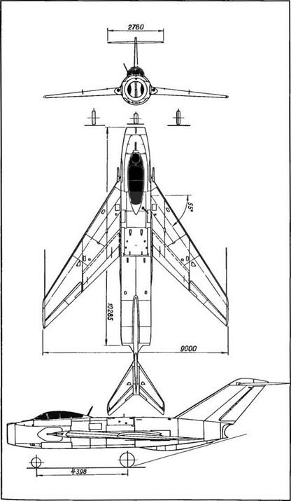
Span, 14.2 m (46 ft 7 in); length, 15.775 m (51 ft 9 in); fuselage length without radome, 12 31 m (40 ft 6 6 in); wheel track, 5.444 m (17 ft 10.3 in); wheel base, 4.754 m (15 ft 7.2 in), wing area, 41.2 m2 (443.5 sq ft); empty weight, 7,367 kg (16,237 lb); takeoff weight, 10,265 kg (22,625 lb); fuel, 2,700 kg (5,950 lb); wing loading, 249.2 kg/m2 (51.1 Ib/sq ft); max operating limit load factor, 8.
Performance
Max speed, 994 km/h at 10,000 m (537 kt at 32,800 ft); max speed at sea level, 1,040 km/h (562 kt); climb to 5,000 m (16,400 ft) in 2.3 min; to 10,000 m (32,800 ft) in 5.65 mm, service ceiling, 15,000 m (49,200 ft); range, 1,100 km (683 mi); takeoff roll, 610 m (2,000 ft); landing roll, 770 m (2,525 ft).
The following details refer to the I-320R-2/R-3 Specifications
Dimensions and area identical to R-l; takeoff weight, 10,725 kg (23,638 lb); max takeoff weight, 12,095 kg (26,657 lb); fuel, 2,700 kg (5,950 lb); fuel with two 750-1 (198-US gal) underslung tanks, 3,950 kg (8,705 lb); wing loading, 260.3-293.6 kg/mz (53.4-60.2 lb/sq ft).
Performance
Max speed, 1,090 km/h at 1,000 m (589 kt at 3,280 ft); max Mach, 0.9; service ceiling, 15,500 m (50,840 ft); range, 1,205 km at 10,000 m (748 mi at 32,800 ft); range with two 750-1 (198-US gal) underslung tanks, 1,940 km (1,205 mi).


