Category Mig

MiG 23UB / 23-51

The decision to build a two-seat trainer for the MiG-23 was made quickly: it was announced in a decree of the council of ministers dated 17 November 1967, fewer than six months after the prototype rollout However, the ministry’s directive went beyond a straightforward train­er and called for some sort of combat capacity—hence the designation UB (Uchebniy Boyevoi training-combat) Derived directly from the MiG-23S, the MiG-23UB was powered by the same engine, the R – 27F2M-300 rated at 6,760 daN (6,900 kg st) dry and 9,800 daN (10,000 kg st) with afterburner. The only structural modifications resulted from the rearrangement of the forward fuselage, the second cockpit taking the place of the equipment hay.

The ministry’s decree allocated the following missions to the new aircraft:

1. Day and night training in clear and adverse weather conditions to teach pilots how to take off, handle the full flight envelope with different types of weapons or dummy missiles, and land

2. Combat within the limits of the aircraft’s weaponry: the GSh-23L cannon, rockets, bombs, air-to-surface missiles (to attack ground or naval targets in visual mode), R-3S infrared-guided air-to-air missiles, or Kh-23 air-to-surface beam-rider guided missiles (since the two-seater had no radar, the latter’s guidance equipment was housed in small pods under the wing glove)

All of this weaponry (except the cannon) was carried under four store points: two under the fuselage and two under the wing glove. In the front cockpit, the student pilot’s equipment included the ASP-PFD fire control system (without the ranging device) and the weapon selec­tion panel. All other controls were duplicated, and the instructor’s set took priority. The nose was weighted to compensate for the lack of radar.

The MiG-23UB differed from the MiG-23S in many points:

1. Structurally, the nose section was modified up to the no. 18 bulk­head to make room for the second cockpit; the equipment bay and the standby hydraulic generator with its windmill were con­sequently moved back by reducing the capacity of fuel tank no. 1 —normally 7001 (185 US gallons)—and, to compensate, adding a tank in the rear fuselage to carry 470 1 (124 US gallons)

2. On-board equipment included the SOUA active angle-of-attack limiter (a few planes that were not so equipped used the SUA-1 critical AOA warning device and the R1S stick shaker), the UUA-1 attitude indicator, the Polyot-11-23 flight management system (including the RSBN-6S landing and short-range navigation device, the SKV-2N2 heading and vertical reference unit, and DV – 30/DV-10 signal transmitters) linked to the SAU-23UB automatic flight control system, three-axis artificial feel units and trims, radio-altimeter, automatic direction finder, marker receiver, the SORTS warning light display panel, IFF interrogator and transponder, radar warning receiver, the SPU-9 intercom, and the MS-61 tape recorder

The MiG-23UB wing, like that of the single-seater, "jumped” from type 1 to type 3. With the type 1 wing the MiG-23UB could carry only a single drop tank under the fuselage; but with the type 3 wing it could carry one drop tank under the fuselage and two drop tanks on non­swiveling pylons under the outer wings for ferry flights. The gear wheels all had brakes, and the two cockpits were equipped with KM-1

A MiG-23UB takes off for a ferry flight, ft has two drop tanks under the outer wmg pan­els. The 16-degree sweep setting will be maintained for the entire flight.

ejection seats and a centralized emergency abandonment system. A periscope was installed on the jettisonable part of the rear canopy so that the instructor could see more clearly while taking off, landing, and taxiing.

The MiG-23UB was rolled out in March 1969 and was first piloted in May by M. M. Komarov. The factory tests (carried out by Komarov and P. M. Ostapyenko) and the state trials lasted until 1970. That year the aircraft was approved for duty in WS and PVO fighter regiments, and it was produced in the Irkutsk factory until 1978.

Specifications

Span (72′ sweep), 7.779 m (25 ft 6.3 in); span (45° sweep), 11.928 m (39 ft 1.6 in); span (16° sweep), 13.965 m (45 ft 9.8 in); fuselage length (except probe), 15.66 m (51 ft 4.5 in); wheel track, 2.658 m (8 ft 8.7 in); wheel base, 5.772 m (18 ft 11.3 in); wing area (72° sweep), 34.16 m2 (367.7 sq ft); wing area (45° sweep), 35.5 m2 (382.1 sq ft); wing area (16° sweep), 37.35 m2 (402 sq ft); takeoff weight, 15,740 kg (34,690 lb); max takeoff weight, 18,000 kg (39,670 lb); landing weight, 12,400 kg (27,330 lb); fuel, 4,000 kg (8,815 lb); with three 800-1 (211-US gal) drop tanks, 6,350 kg (13,995 lb); wing loading (72° sweep), 460.8-526.9 kg/m2 (94.5-108 Ib/sq ft); wing loading (45° sweep), 443.4-507 kg/m2

The MiG-23M was built in the greatest numbers This one carries two R-60R and four R-60T air-to-air missiles.

(90.9-103.9 lb sq ft); wing loading (16° sweep), 421.4-481.9 kg/m2 (86.4-98.8 lb/sq ft); max operating limit load factor, 7.

Performance

Max speed in clean configuration (72° sweep), 2,490 km/h or Mach

2.35 at 12,500 m (1,344 kt at 41,000 ft); max speed in clean configura­tion at sea level (72° sweep), 1,200 km/h (648 kt); max operating Mach number, 2.35; max operating Mach number with four R-3S mis­siles, 2; max operating Mach number with four R-3S missiles and 800-1 (211-US gal) drop tank, 0.8; service ceiling, 15,800 m (51,825 ft).

YB-155M / 99 / Ye-2BGM / Experimental Versions

While confirming the acceptance of the MiG-25RB, the decree signed by the council of ministers in 1972 outlined the path of future updates for the MiG-25 family The WS command was already asking for a range increase at medium and high altitudes, as well as more speed and a higher service ceiling The Mikulin-Tumanskiy OKB proposed the R-15BF-2-300, an upgraded R-15B-300 rated at 13,230 daN (13,500 kg st) with afterburner—an increase of 3,225 daN (3,290 kg st)—that retained the size and connection points of the existing engine and rea­sonable specific fuel consumption

Development of the new aircraft was to happen in two stages First the range and rate of climb would be enhanced without structural mod­ifications The aircraft would be reengined after their operational life expired—a sure way to grow younger. Second, the aircraft structure would be modified, removing the little duralumin still used in the for­ward fuselage and the few non-heat-resisting wing elements so that the aircraft could fly at speeds above Mach 3. The MiG-25’s never-exceed Mach number (Mne) of 2.83 was in fact somewhat theoretical: the later­al stability margin and the structural lifetime were supposed to dimin­ish beyond that figure, but a number of pilots have (more or less inten­tionally) exceeded Mach 3 without causing damage to the aircraft or sending it to the overhaul shop to check for structural yielding.

The first stage was carried to a successful conclusion. The factory designation of the new product was Ye-155M, but the certification doc­uments sent to the FAI after several record attempts in 1975 and 1977 called it the Ye-266M. Unfortunately, the excessive engine develop­ment time and the lack of factory availability delayed the second stage of the upgrade; as a result these modifications either remained experi­mental or did not go beyond the computational phase.

Nevertheless, the results obtained during the first step were very encouraging compared with the MiG-25P or R performance. The ser­vice ceiling increased to 24,200 m (79,375 feet), and the range at super­sonic speed to 1,920 km (1,190 miles)—2,510 km (1,560 miles) if one adds the auxiliary tank’s 5,300 1 (1,400 US gallons). Another R & D channel consisted of powering the Ye-155M with two D-30F turbofan engines rated at 15,190 daN (15,500 kg st) with afterburner. It was developed by P. A. Solovyev out of the core engine of the D-30, the power plant capable of 6,665 daN (6,800 kg st) that had powered the Tupolev Tu-134 twin-jet airliner since 1963.

This engine change led to significant structural modifications that did not, however, change the aircraft’s silhouette drastically; and the fuel capacity was raised to 19,700 1 (5,200 US gallons). Two prototypes were constructed with two D-30Fs. They were used essentially as test beds for developing the engine that would later power the MiG-31. The takeoff weight of this variant reached 37,750 kg (83,200 pounds), the maximum takeoff weight 42,520 kg (93,715 pounds), and the internal fuel weight 16,270 kg (35,860 pounds). Due to the turbofan’s better spe­cific fuel consumption its range on internal fuel reached 2,135 km (1,325 miles) at supersonic speeds and 3,310 km (2,055 miles) at sub­sonic speeds. Its service ceiling topped out at 21,900 m (71,830 feet).

Ye-266M Records

The documents sent to the FAI showed that the Ye-266M was powered by two turbojets rated at 13,720 daN (14,000 kg st). In fact, the aircraft was powered by two R-15BF-2-300 turbojets at 13,230 daN (13,500 kg st). These six world records (including one absolute world record), established more than fifteen years ago, were still standing as this book went to press.

17 May 1975

Time to climb to 25,000 m (82,000 feet), 2 minutes, 34.2 seconds. Pilot, A. V. Fedotov

Time to climb to 30,000 m (98,400 feet), 3 minutes, 9.85 seconds. Pilot, P. M. Ostapyenko

Time to climb to 35,000 m (114,800 feet), 4 minutes, 11.7 seconds. Pilot, A. V. Fedotov 22 July 1977

Altitude with a 2,000-kg (4,400-pound) payload, 37,080 m (121,622 feet). Pilot, A. V. Fedotov

Altitude with a 1,000-kg (2,200-pound) payload, 37,080 m (121,622 feet). Pilot, A. V. Fedotov 31 August 1977

Altitude without payload, 37,650 m (123,492 feet). Pilot, A. V. Fedotov. Absolute world record

1305 / FL

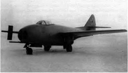
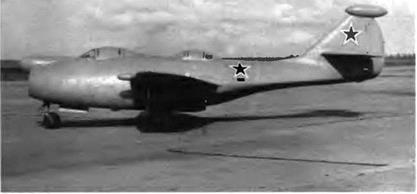
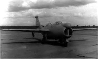
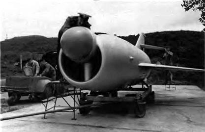
One MiG-9 airframe was to be reengined with a single 1,470-daN (1,500-kg st) TR-1A turbojet developed by A M. Lyulka. While match­ing the performance level of the production model, the design takeoff weight of the FL was 350 kg (770 pounds) lower.

To fit the TR-1A—the first jet engine developed and built entirely in USSR—into the airframe in place of the two BMW 003s, the tail sec­tion of the fuselage had to be modified. Moreover, the engineers left room for an afterburner then in the works that would boost the thrust to 1,960-2,450 daN (2,000-2,500 kg st).

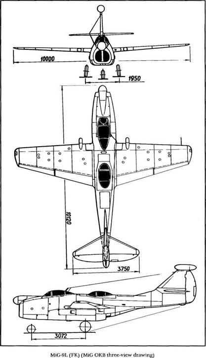
The 1-305 was an important aircraft first and foremost because of its built-in potential. The cannon arrangement was again modified; all three arms were now on the same horizontal plane. One experimental N-37 (120P) with forty-five rounds occupied the middle space, with one NS-23 (115Р) with 80 rpg on either side. The 1-305 featured a pressur­ized cockpit and an ejection seat. To improve the aircraft’s operational efficiency, most of the systems were to have been upgraded with the RSIU-10 transceiver, the Baryum-1 IFF, the N1-46 ground position indi­cator, and the Ton-3 direction finder.

The 1-305 airframe was almost completed at the end of 1947 Unfortunately, the TR-1A turbojet burst soon afterward on the test

image96

For the FL, the armament arrangement was modified once more. The three cannons were placed on the same horizontal plane

bench At that time a brand-new aircraft, the 1-310 S (commonly known as the MiG-15) looked like a more promising venture As a result the FL was discontinued.

Specifications

Span, 10 m (32 ft 9.7 in); length, 9.7 m (31 ft 9.8 in); height in level flight position, 3.2 m (10 ft 9.9 in); wheel track, 1.95 m (6 ft 4.8 in); wheel base, 3 32 m (10 ft 10.7 in), wing area, 18.2 m2 (195.9 sq ft); takeoff weight, 4,570 kg (10,072 lb); fuel, 1,485 1 (386 US gal); wing loading, 261 kg/m2 (53.5 lb/sq ft).

Performance

Max speed, 885 km/h at 5,000 m (478 kt at 16,400 ft); max speed at sea level, 897 km/h (484 kt); climb to 5,000 m (16,400 ft) in 4 86 min; to 10,000 (32,800 ft) in 13.24 min; service ceiling, 13,400 m (43,950 ft); landing speed, 155 km/h (84 kt); range at 10,000 m (32,800 ft), 1,050 km (652 mi), takeoff roll, 815 m (2,675 ft); landing roll, 665 m (2,180 ft).

image97

MHM5P bis / SP-1

The development of an all-weather fighter for the PVO had become a necessity. When the first Soviet airborne radars appeared at the end of the 1940s, it was decided that the MiG-15 bis would receive this advanced equipment. But first a number of questions had to be answered regarding the capabilities and efficiency of both the radar control unit when engaging enemy aircraft and the sighting system in blind flying (at night or in clouds).

The council of ministers called for development work on both the airborne radar and the aircraft on 7 December 1948. The first ranging

image136

Installation of the Toriy radar on the MiG-15P bis necessitated alteration of the fuse­lage nose structure up to the no. 8 frame

radar, the Toriy, was developed by A. B. Slepushkin, pioneer of Soviet radar technology. It was a peculiar system: its one antenna both trans­mitted and received signals. It was housed in a small radome made of a specially developed dielectric material. The Toriy was not easy for the pilot to control while trying to intercept enemy aircraft because it could not track targets automatically.

From the start MiG OKB engineers were determined not to let the efficiency and performance of the MiG-15 bis suffer because of the addition of radar. Production MiG-15 bis no. 3810102 built at factory no 1 was sent to the OKB workshop and modified, becoming the SP-1. The two guns on the left of the fuselage were removed; only the N-37D with forty-five rounds was retained. The ASP-3N gunsight was replaced by a new model, and the S-13 camera gun usually placed above the air intake was moved to the right side of the fuselage. Most important, a radar display was set into the instrument panel. With that display the pilot was able to track an invader, bring his aircraft into line with it, and measure its distance before firing.

As it turned out, many other modifications had to be made, mainly structural ones:

—because of the radar installation and armament removal, the fuse­lage nose section was made over up to the no. 8 frame and length­ened by 120 mm (4.7 inches)

—the area of the airbrakes was increased, and their shape and axis of rotation were altered (22 degrees in relation to the vertical)

—the cockpit windshield was fitted with 64-mm-thick bulletproof glass, and the shape of the windshield and the canopy was changed in order to retain a good forward view despite the nose modifications

—the wing anhedral was increased from 2 to 3 degrees —the front leg of the landing gear had to be moved 80 mm (3.5 inch­es) forward to bring the NR-37 cannon axis as close as possible to the aircraft datum line

—the wheel fork was replaced by a half-fork, and the double gear doors were replaced by a single door —the elevator control was fitted with a BU-1 servo-control unit

The SP-1 prototype was equipped with an ARK-5 automatic direc­tion finder and an MRP-48 marker receiver. After the factory flight tests conducted in December 1949 by A. N. Chernoburov and G. A. Sedov, the aircraft was transferred to the Nil WS on 31 January 1950 for its state trials. They ended on 20 May 1950.

The test report noted a number of defects. The pitching stability was too scanty at landing, and compared with the MiG-15 (SV) the dynamic stability margin had decreased. In straight level flight, the air­craft tended to bank to the left and then side-slip at 940-950 km/h (508-513 kt) Poor aileron efficiency limited the bank angle to 5 degrees.

The report concluded that the SP-1 could not be used as an all – weather interceptor because its Toriy ranging radar did not work properly. The all-weather radar tests were conducted by Suprun, Kalachev, Pibulyenko, Blagoveshchenkiy, Antipov, Dzyuba, and Ivanov, all military pilots. Several passes were made in attempts to locate 11-28 and Tu-4 bombers. The SP-1 was not certified because it was too difficult for a pilot to fly his aircraft and operate the radar at the same time—and moreover, the Toriy was not very reliable. Its manufacturer upgraded the unit, which then became known as the Toriy A and was installed on the MiG-17 (SP-2). But its most serious shortcoming was not addressed: the Toriy A still could only track incoming aircraft manually.

In 1951 five SP-ls equipped with RP-1M radars were assembled at factory no. 1. On 25 November one was sent to the Nil WS for trials, but the aircraft and its upgraded radar unit still failed to earn certifica­tion. Like the MiG-15 bis, the MiG-15P bis (SP-1) was powered by a 2,645-daN (2,700-kg st) VK-1 turbojet.

Specifications

Span, 10.085 m (33 ft 1 in); overall length, 10.222 m (33 ft 6.5 in); wheel track, 3.852 m (12 ft 7.6 in); wheel base, 3.075 m (10 ft 1.1 in);

image137

On the MiG-15P bis the two NR-23 cannons usually found at the lower left of the MiG – 15 bis front fuselage had to be removed.

image138

The wing anhedral of the MiG-15P bis was increased slightly, as was the area of the air­brakes.

image139

The SD-21 was a MiG-15 bis used for testing S-21 rockets, hence its designation.

wing area, 20.6 m2 (221.7 sq ft); empty weight, 3,760 kg (8,287 lb); takeoff weight, 5,080 kg (11,196 lb); fuel, 1,168 kg (2,574 lb); wing load­ing, 246.6 kg/m2 (50.55 lb/sq ft).

Performance

Max speed, 1,022 km/h at 5,000 m (552 kt at 16,400 ft); 979 km/h at 10,000 m (529 kt at 32,800 ft); climb to 5,000 m (16,400 ft) in 2.15 min; to 10,000 m (32,800 ft) in 5.35 min; service ceiling, 14,700 m (48,200 ft); range, 1,115 km at 10,000 m (692 mi at 32,800 ft); takeoff roll, 510 m (1,670 ft).

MiG 17 / SI-ID

This experimental version was developed to improve the handling of the MiG-17 by modifying its lift devices and adding a variable inci­dence stabilizer. This effort was made in the context of a plan drawn up by the ministry of aircraft production between 26 and 30 March 1953 to eliminate some of the shortcomings revealed during flight tests. The SI-10 was built with the MiG-17 no. 214 airframe. It differed from the production machine in several ways

—the Fowler-type wing flaps were replaced by split flaps with take­off and landing deflections of 16 and 25 degrees, respectively

image178

Three technical innovations on MiG-17 no 214 automatic slats on the leading edge of the wing, spoilers, and variable incidence stabilizer with elevator

—67 percent of the wing’s leading edge was taken up by automatic slats (maximum extension angle 12 degrees)

—the standard stabilizer was replaced by a variable incidence stabi­lizer with elevator (surface deflection -5 to +3 degrees)

—the SI-10 received the first spoilers ever installed on a MiG fighter, with their operation linked to that of the ailerons located on the lower surface of the wing, they extended 55 millimeters (2.16 inches) downward when the aileron displacement was greater than 6 degrees

—the wing fences were removed

The SI-10 was probably the most technically advanced fighter of its time. All of these modifications added weight to the aircraft, however: the new stabilator, 28 kg (62 pounds); spoilers, 14 kg (31 pounds); slats and flaps, 120 kg (265 pounds); and the balance weight, 70 kg (154 pounds).

The aircraft was rolled out at the end of 1954. It was powered by a VK-1A turbojet rated at 2,645 daN (2,700 kg st). Armament consisted of one N-37D and two NR-23 cannons The factory tests took place in early 1955 with G. K. Mosolov, G. A. Sedov, and A. N. Chemoburov at the controls State trials were completed in July Four GK Nil VVS

image179

Close-up of the SI-10’s deep-chord leading edge slats

image180

The SI-10 wing with lift augmentation at its best: automatic slats at their maximum extension angle of 12 degrees, and split flaps at their maximum deflection of 25 degrees

Comparison of the Takeoff and Landing Performance of the SI-10 and SI-02

Aircraft

SI-10

SI-02

Takeoff roll

560 m (1,835 ft)

535 m (1,755 ft)

Takeoff speed

232 km/h (125 kt)

232 km/h (125 kt)

Runway needed for takeoff

1 070 m (3,510 ft)

1 260 m (4,130 ft)

Landing roll

1 095 m (3,590 ft)

825 m (2 700 ft)

Landing speed

194 km/h (105 kt)

190 km/h (103 kt)

Runway needed for landing

1,650 m (5,410 ft)

1,460 m (4,790 ft)

Angle of flaps at takeoff/landmg

l6°/25°

20V60"

Source: MiG OKB

pilots participated in these tests S A. Mikoyan, A. P. Molotkov, V. N. Makhalin, and N. A. Korovin. They made forty-seven flights and spent thirty-two hours and ten minutes in the air. The tests proved that the variable incidence stabilizer and spoilers’ action on the pitch control significantly improved the aircraft’s handling characteristics, especially at high speeds and altitudes. However, the addition of the slats and the modification of the flaps did not seem to have any effect.

Specifications

Span, 9 628 m (31 ft 7 in); length, 11 264 m (36 ft 11.5 in), height, 3.8 m (12 ft 5 6 in); wheel track, 3 849 m (12 ft 7.5 in); wing area, 22,6 m2 (243.3 sq ft); empty weight, 4,140 kg (9,125 lb); takeoff weight, 5,490 kg (12,100 lb); fuel, 1,128 kg (2,486 lb); wing loading, 242.9 kg/m2 (49.8 lb/sq ft).

Performance

Except as noted in the table above, the SI-10’s performance data were almost identical to those of the MiG-17 (SI-02).

MiG-19SU / SM 50/SM 51/SM-52

Still faster, still higher: those two imperatives summed up the develop­ment requests received from military authorities such as the WS and the PVO. They also summed up the specifications of the SM-50 and SM-51, two prototypes of a high-speed interceptor with a lofty service ceiling.

The SM-50 was powered by two AM-9BMs whose reheated thrust was 3,135 daN (3,200 kg st) and by the U-19 booster container with two power ratings: 1,275 daN (1,300 kg st) and 2,940 daN (3,000 kg st). The rocket engine could not be relit in flight. The SM-51 was powered by two Sorokin R3M-26 experimental turbojets derived from the AM-9BM with 3,725 daN (3,800 kg st) of thrust and by the U-19D booster contain­er. Its rocket engine had the same thrust as that of the U-19 but could be turned off and relit four times in flight. The SM-50 was developed from the MiG-19S, while the SM-51 was developed from the MiG-19P.

image218

The single ventral fin of the MiG-19S had to be replaced by two well-spaced fins on the SM-50 because of the rocket engine exhaust.

The booster container, planned by D. D. Sevruk and built at the MiG ОКБ, was fastened under the fuselage. It was composed of:

—the RU-013 rocket engine

—three tanks: one for the TG-02 fuel, one for the AK-20 oxidizer, and

one for the concentrated hydrogen peroxide —the combustion chamber feed pumps —the replenishment system for the three tanks —the dump valves

The rocket engine weighed 338 kg (745 pounds); the fuel, 372 kg (820 pounds); the oxidizer, 112 kg (247 pounds); and the hydrogen per­oxide, 74.2 kg (163.5 pounds). The U-19 and U-19D booster containers operated almost autonomously; their only links to the cockpit were the electrical ignition control and the dump valve control.

Both the SM-50 and SM-51 were armed with two NR-30 cannons located in the wing roots. The SM-51 was equipped with an RP-5 Izum – rud radar. The takeoff weight of both aircraft—including the booster container—was 9,000 kg (19,835 pounds).

All factory test flights of the SM-50 and SM-51 were made by V. A. Nefyedov under the supervision of Yu. N. Korolyev, chief engineer.

image219

The rocket engine contour gave the SM-50 a very strange silhouette.

Their maximum speed was 1,800 km/h (972 kt), their dynamic ceiling was 24,000 m (78,700 feet), and they could climb to 20,000 m (65,600 feet) in eight minutes. Their range—not an important factor for this type of aircraft—was limited to 800 km (497 miles). The state trials of the SM-50 were carried out by two LII pilots, M. M. Kotelnikov and A. A. Shcherbakov. Five SM-50s were built in factory no. 21.

The SM-52 was identical to the SM-51 with the exception of its radar, which was the Almaz (“diamond") model.

Ye l/Kh-1 / Ye-2/Kh 2

In the first half of the 1950s the military called for the development of a lightweight frontline fighter capable of speeds of Mach 2 and a ser­vice ceiling of 20,000 m (65,600 feet). Initial work was concerned with the test and aerodynamic refinement of a set of thin-airfoil wings char­acterized by a 55- to 57-degree sweepback at the leading edge, with the

The Ye-2 had half-span leading edge slats

design of reliable flying controls for transonic speeds and Mach num­bers between 1.5 and 1.7, and with the selective examination of all pos­sible power plants—including several types of turbojets associated with supersonic air intakes.

279

Ye-2; second from top, sidfi view of the Ye-2A (MiG OKB four-view drawing)

Such were the basic considerations that led in 1954 to a prelimi­nary design named Ye-1 or Kh-1 and powered by the AM-5A turbojet. This first draft was quickly modified during that same year and became the Ye-2 powered by the AM-9B turbojet with afterburner, a Mikulin engine that had been retained to power the mass-produced MiG-19. (The AM-11 was the engineers’ first choice, but it was not yet avail­able.) The Ye-2 was planned as a single-engine fighter and thus had 2,550 daN (2,600 kg st) of thrust available, or 3,185 daN (3,250 kg st) with afterburner.

It was decided to keep the aircraft’s master cross-section as little as possible because it was proportioned by the small volume of the cock­pit (1 m3 [35.3 cubic feet]) and the dimensions of the engine. The two – spar stressed-skin wing had a sweepback of 55 degrees at the leading edge and a thickness ratio of 6 percent. The Fowler flaps were hydraulically controlled. The two-segment ailerons were mechanically linked to the spoilers. The outer halves of the leading edge were fitted with two-segment slats. The cockpit canopy structure and the ejection seat were identical to those aboard the 1-3, and the canopy protected the pilot in case of ejection.

The windshield was heated by electrical wires set into the triplex glass interlayer. Flying controls were of the rigid type, the rudder being controlled by actuating rods that extended through the dorsal spine of the fuselage behind the cockpit. The slab tailplane was controlled by a servo-control unit located in the fin root. Each of the four fuselage tanks was cut off from the others by special nonreturn valves in order to improve the fuel system’s fatigue resistance. The turbojet plus after­burner bay was cooled by ventilation between the combustion cham­ber shroud and the fuselage skin. As the aircraft accelerated, ventila­tion was relative to ram air pressure; at zero airspeed, the engine bay was cooled by the discharge of sucked-in air.

The landing gear took up much less space. The main gear wheels retracted into the fuselage, while their legs folded into the wing between the fuel tank/wing box and the rear spar on which the flaps were hinged. This mechanism was later used on several types of MiG fighters because it cut the structure’s weight significantly. Armament consisted of two NR-30 cannons located in the lower part of the nose. The ammunition belts were housed in circular sleeves placed between fuselage bulkheads. Main equipment and accessories included the RSIU-4 VHF, the Uzel system’s homing receiver, the ARK-5 automatic direction finder, the MRP-48 ILS, the Radal-M ranging radar linked to the ASP-5N gunsight, and a radar warning receiver.

The Ye-2 was first piloted by G. K. Mosolov on 14 February 1955 but finished only a part of its test schedule, which was completed by the reengined Ye-2A.

Specifications

Span, 8 109 m (26 ft 7 2 In); length (except probe), 13.23 m (43 ft 4 9 in); fuselage length (except cone), 11 737 m (38 ft 6 1 in); wheel track, 2.679 m (8 ft 9 5 in); wheel base 4.41 m (14 ft 5.6 in); wing area, 21 m2 (226 sq ft), empty weight, 3,687 kg (8,125 lb), takeoff weight, 5,334 kg (11,755 lb) fuel, 1,360 kg (3,000 lb), wing loading, 254 kg/m2 (52 lb/sq ft)

Performance

Design max speed, 1 920 km/h (1,037 kt); landing speed, 250 km/h (135 kt), design service ceiling, 19,000 m (62 300 ft), takeoff roll, 700 m (2,295 ft), landing roll, 800 m (2 625 ft)

MiG-21SIVI / 7//УІ5

The MiG-2 ISM, the continuation of the "Meccano” game started with the Ye-6, evolved from a M1G-21S airframe on which two significant modifications were made. First, the new aircraft was powered by a more powerful turbojet developed by S. Gavrilov: the R-l 3-300, rated at 3,990 daN (4,070 kg st) dry and 6,360 daN (6,490 kg st) with afterburn­er Second, it was armed with aburlt-in twin-barrel GSh-23L cannon with 200 rounds (the same weapon in a gun pod caused too much drag) The lessons of air battles in the Middle East finally registered, and the concept of a fighter armed only with missiles was flatly aban­doned. The new ASP-PFD gunsight was designed specifically for com­bat situations requiring tight, high-g maneuvers The aircraft was equipped with the RP-22 Sapfir-21 and the SPO-10 radar warning receiver

In addition to the built-in cannon, armament included two K-13T (R-3S) or two K-13R (R-3R) air-to-air missiles, and/or UB-16 and UB-32 rocket pods, S-24 large-caliber rockets, four 100-kg (220-pound) bombs, and napalm containers The total fuel capacity of this variant was reduced to 2,650 1 (700 US gallons) The MiG-21SM was mass-produced for the WS in the Gorki factory between 1968 and 1974.

Specifications

Span, 7,154 m (23 ft 5.7 in), fuselage length (except cone), 12 286 m (40 ft 3 7 in); wheel track 2.787 m (9 ft 1 7 in), wheel base, 4.71 m (15 ft 5.4 in); wmg area, 23 m2 (247.6 sq ft); takeoff weight, 8,300 kg (18,295 lb); max takeoff weight, 9,100 kg (20,055 lb); max takeoff weight on rough strip or metal-plank strip, 8 800 kg (19,395 lb), wing loading, 360.9-395.7-382.6 kg/m2 (74-81 1-78.4 lb/sq ft), max operating limit load factor 8.5

Performance

Max speed, 2,230 km/h at 13,000 m (1,204 kt at 42,640 ft); max speed at sea level, 1,300 km/h (702 kt); climb rate at sea level in clean con­figuration, 160 m/sec (11,930 ft/min); climb to 17,500 m (57,400 ft) in 9 min; service ceiling, 18,000 m (59,000 ft); landing speed, 250 km/h (135 kt); range, 1,050 km (650 mi); with 800-1 (211-US gal) drop tank, 1,420 km (880 mi); takeoff roll, 800 m (2,625 ft); landing roll with SPS and tail chute, 550 m (1,800 ft).

MiG 23M / 2311 / MiG 23MF / MiG 23MS

The МЮ-23М took the place of the MiG-23S on the assembly lines. It was the long-awaited production aircraft whose arrival had been hin­dered by delays in the development of its systems (especially the radar) and its engine (whose thrust was inadequate to achieve the design parameters). Its wing chord was broader, leading to that distinc­tive dogtooth at the inner end of the leading edge and also a larger

367

MiG-23MS (MiG ОКБ three-view drawing)

This MiG-23M carries R-23T and R-23R air-to-air missiles under the wing gloves. The four store stations under the fuselage are fitted with R-60Ts. The TP-23 infrared sensor is visible under the radome.

This MiG-23M has a type 2 wing, with its deeper chord and dog-toothed edge but no leading edge flaps. The four airbrakes are deployed.

The MiG-23MS was intended for export and equipped with less sophisticated radar and other systems

wing area. This was the type 2 wing, without leading edge flaps; but the MiG-23M was later retrofitted with type 3 wing, its four-part lead­ing edge flaps linked to those on the trailing edge as they retracted or extended.

It also had a different engine, the new Khachaturov R-23-300 rated at 8,135 daN (8,300 kg st) dry or 12,250 daN (12,500 kg st) with after­burner. And its systems were different: the S-23D-Sh forward-sector scanning and fire control system; the Sapfir-23-Sh radar; the TP-23 infrared sensor; the ASP-23D fire control device; and SAU-23A second – series automatic flight control system with the ARZ-1A feel computer on the pitch channel capable of taking the aircraft’s speed, altitude, and sweep angle into account.

Because of the missions allotted to the MiG-23M—interception, air combat, and attack of ground and naval targets—its weapon system included the GSh-23L twin-barrel cannon embedded under the fuselage on its easy-access hoisting tray and, at four store stations (two under the fuselage, two under the wing glove), radar-guided R-23R, IR-guided R-23T, R-13M air-to-air missiles, R-3A training missiles, B-8 rocket pods (firing S-8 rockets), UB-32 rocket pods (firing S-5 rockets), bombs of var­ious types and weights, submunitions dispensers, R-60 close-range air – to-air missiles, S-24 unguided air-to-surface rockets, and a pod housing the guidance system for air-to-surface missiles. The aircraft was decked out with an armament control panel.

Maximum internal fuel capacity was raised to 4,700 1 (1,241 US gal­lons) thanks to a fourth fuel tank in the rear fuselage The MiG-23M could also cany three drop tanks holding 7901 (209 US gallons) apiece, one under the fuselage and two under the wing glove) First piloted in June 1972 by A V. Fedotov, this model was the most popular MiG-23 and originated two export versions, the MiG-23MF and MiG-23MS, they carried less-advanced systems, armament (R-3S/R-3R missiles), and engines (the M1G-23MS used the R-27F2M-300), and their camouflage paint varied according to where they operated MiG-23M MF, and MS aircraft have taken part in several local conflicts in the Middle East and Afghanistan.

Specifications

Span (72° sweep), 7 779 m (25 ft 6 3 in); span (16° sweep) 13 965 m (45 ft 9 8 in); fuselage length (except probe), 15 73 m (51 ft 7 3 in); wheel track 2.658 m (8 ft 8 7 in); wheel base, 5 772 m (18 ft 11 3 in); wing area (72° sweep), 34 16 m2 (367.7 sq ft), wing area (16° sweep), 37 35 m2 (402 sq ft), takeoff weight, 15,750 kg (34,715 lb), max takeoff weight, 18 400 kg (40,555 lb), max takeoff weight with 790-1 (209-US gal) drop tank, 19,130 kg (42 160 lb), with two 790-1 (209-US gal) drop tanks 19,940 kg (43,950 lb); with three 790-1 (209-US gal) drop tanks, 20,670 kg (45 555 lb), internal fuel, 3 800 kg (8,375 lb), wing loading (72° sweep), 461-605 kg/m2 (94.5-124 lb sq ft); wing loading (16° sweep), 421 7-553 4 kg/m2 (86 4-113 4 lb/sq ft); max operating limit load factor (45° sweep), 8 at < Mach 0.85 7 at > Mach 0 85

Performance

Max speed in clean configuration (72 ” sweep), 2 490 km/h or Mach

2.35 at 12,500 m (1,344 kt at 41 000 ft); max speed in clean configura­tion (16° sweep), 935 km h or Mach 0.8 at 3,500 m (505 kt at 11 500 ft)

MiG-25BM / 02M

The goal of this project was to develop (from the MiG-25RB) an aircraft capable of destroying the enemy’s air defenses, especially ground radars. Ordered by a decree of the council of ministers in 1972, the 02M product was equipped with powerful electronic countermeasures and Kh-58 antiradiation missiles. Those missiles took the place of the bombs under the wing pylons, and the elongated nose housed the ECM equipment. The cockpit instrumentation, the aircraft’s power supply, and the air-conditioning system had to be modified because of the new missions.

The weights and performance of the MiG-25BM were practically identical to those of the MiG-25RB. After passing its certification tests, the aircraft was produced in the Gorki factory between 1982 and 1985.