Category Mig

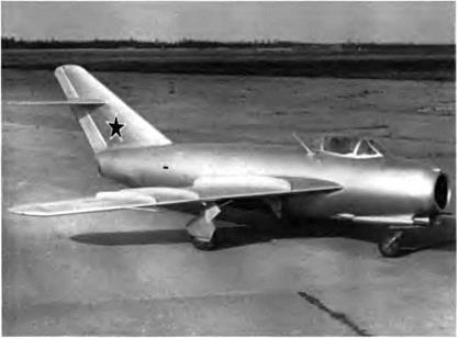
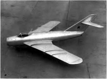
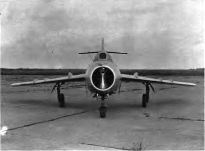
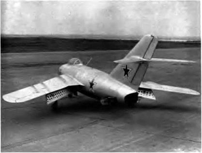
MiG 19S / SM-9/2 and SM-9/3

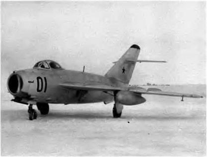
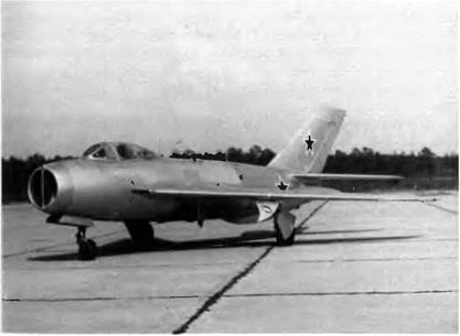
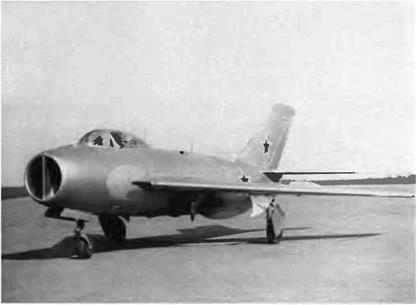
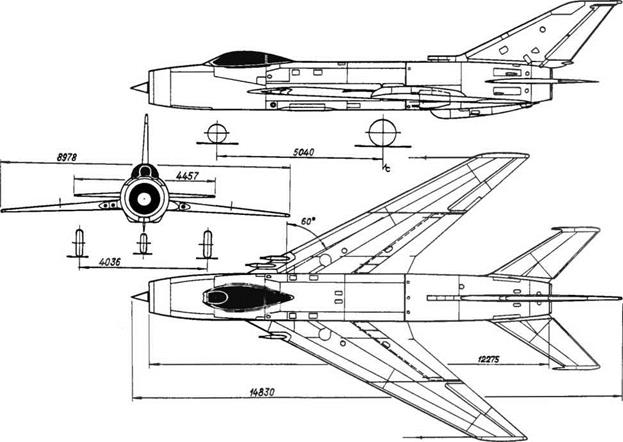
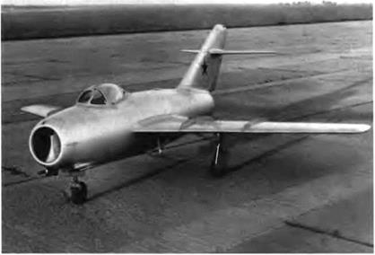
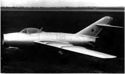
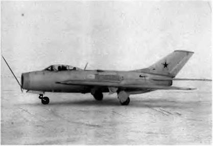
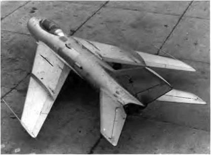
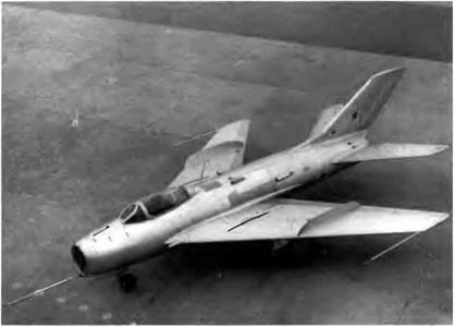
Development of the next two prototypes, the SM-9/2 and SM-9/3, was intended to improve the handling of the MiG-19 with a stabilator or slab tailplane. While satisfactory on the whole, tests of the SM-9/1 uncovered some inadequacies, especially a decreasing linear accelera­tion at supersonic speeds The answer was to design a linkage for the stabilator control that would generate acceptable control column forces and prevent the pilot from imparting a longitudinal swing to the aircraft through the whole range of speeds and altitudes. Test flights made by G. A. Sedov, К. K. Kokkinaki, and V. A. Nefyedov demonstrat­ed the necessity of such a device. On several occasions the SM-9/2 reached very dangerous flight regimes, mainly when the aircraft start­ed to swing and the pilot’s use of the stabilator did nothing but increase the swing rate.

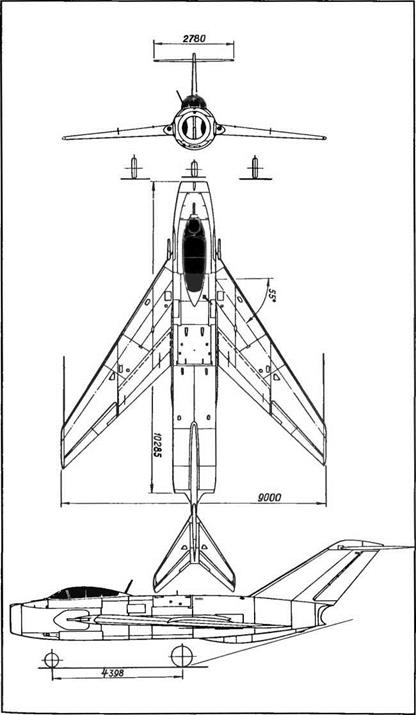
The SM-9/2 and SM-9/3 were built in 1954, one after the other. They differed from the SM-9/1 in their slab tailplane and other details:

—for the first time, ejection of the cockpit hood was controlled by pneumatic cylinders

—to increase the efficiency of the lateral control at high Mach num­bers, spoilers mechanically linked to the ailerons were placed ahead of the flaps on the underwing

image202

The SM-9/3 was the master aircraft for the mass-produced MiG-19.

—both pitch and roll channels were equipped with irreversible servo-controls driven by their own hydraulic circuit, the utility hydraulic system being used as a backup system; switching over the utility system was automatic when hydraulic pressure dropped below 65 kg/cmz (925 psi)

—the pitch control system (actuating rods) was, as a master control, equipped as well with an irreversible servo-control, the utility hydraulic system being also used as a standby system —the slab tailplane had both third – and fourth-level emergency con­trols (an electromechanism actuated by the control column itself and a set switch on the column, respectively), the electromech­anism cut in automatically when hydraulic pressure dropped below 50 kg/cm2 (710 psi)

—the gear ratio between the control column and the slab tailplane changed according to the dynamic pressure and flight altitude— that is, according to the Mach number—thanks to the ARU-2A automatic feel control unit. The control column forces on the lon­gitudinal axis were controlled by a Q-spring assembly in the ARU – 2A mechanism. The aerodynamic hinge moment of the slab tailplane was not fed back to the column. This device allowed the pilot to master the aircraft’s handling characteristics without hav­ing to think about the dynamic pressure or the Mach number. It was designed, tested, and built by a highly talented engineer and a historian of aviation, A. V. Minayev, who broke new ground in the field of flying control systems and was later appointed chief con­structor and denutv minister of aircraft Droduction.

image203

—a 0.54-m2 (5.8-square foot) ventral fin was added to improve direc­tional stability

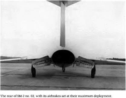
—both prototypes were equipped with three airbrakes, two flanking the rear fuselage and one under the middle part of the fuselage

The armament of the SM-9/2 consisted of three NR-23 cannons (two in the wing roots and one on the right side of the lower forward fuselage). It could also carry two or four rocket pods for 57-mm ARS-57 rockets. The main on-board systems included the RSIU-4 Dub (“oak") VHF, the SRO IFF transponder, a radar warning receiver, the SRD-3

image204

The MiG-19S had a slab tailplane and a third airbrake under the fuselage developed on the SM-9/3.

Grad (‘’hail”) or SRD-1M Konus (“cone") ranging radar linked to the AS P-5 M gunsight, and the OSP-48 ILS. The SM-9/2 was moved to the flight test center in September 1954 and was taken up by G. A. Sedov on 16 September.

As of 4 May 1955 the OKB and GK Nil VYS pilots had made fifty – eight flights and noted the outstanding qualities of the SM-9/2, espe­cially its climb rate of 180 meters per second (35,400 feet per minute) at sea level. The appraisal of OKB pilots Sedov, Mosolov, Kokkinaki, and Nefyedov and Nil WS pilots Blagoveshchenskiy, Antipov, Ivanov, Molotkov, Beregovoy, and Korovin was very positive. The state trials proved that both prototypes were sufficiently long-legged for fighters with a range of 1,300 km (810 miles), and that the sound barrier was no longer a barrier at all. Because of the ARU-2, the slab tailplane, and many other technological advances, the shortcomings of the SM-2 were just a bad memory now.

The aircraft was continuously updated during the tests. For exam­ple, its balance range at takeoffs and landings was increased by short­ening the displacement of the control column. Mosolov reached Mach 1.462 in the SM-9/2 by starting a dive at 9,300 m (30,500 feet). The SM – 9/3 was rolled out on 26 August 1955 and went up for its first flight on 27 November with Kokkinaki at the controls.

The SM-9/3 differed slightly from the SM-9/2. The three NR-23 cannons of the latter were replaced by three NR-30s. A one-second salvo weighed 18 kg (40 pounds) as opposed to 9 kg (20 pounds) in the

SM-9/2. The SM-9/3 also reached Mach 1.46 and became the master aircraft for the MiG-19, which was mass-produced in two factories.

Specifications

Span, 9 m (29 ft 6.3 in); length (except nose probe), 12.54 m (41 ft 1.7 in); overall length, 14.64 m (48 ft 0.4 in); fuselage length, 10.353 m (33 ft 11.6 in); height with depressed shock struts, 3.885 m (12 ft 8.9 in); wheel track, 4.156 m (13 ft 7.6 in); wheel base, 4.398 m (14 ft 5.2 in); wing area, 25 m2 (269 sq ft); takeoff weight, 7,560 kg (16,660 lb); max takeoff weight with two 760-1 (201-US gal) drop tanks and two rocket pods, 8,832 kg (19,466 lb); fuel, 1,800 kg (3,970 lb); wing loading, 302.4-353.3 kg/m2 (62-72.4 lb/sq ft).

Performance

Max speed, 1,452 km/h at 10,000 m (784 kt at 32,800 ft); with two 760-1 (201-US gal) drop tanks, 1,150 km/h (620 kt); max operating limit Mach number, 1.44; climb to 5,000 m (16,400 ft) in 0.4 min; to 10,000 m (32,800 ft) in 1.1 min; to 15,000 m (49,200 ft) in 2.6 min; range, 1,390 km at 14,000 m (860 mi at 45,900 ft); with two 760-1 (201-US gal) drop tanks, 2,200 km (1,365 mi); service ceiling, 17,500 m (57,400 ft); dynamic ceiling, 20,000 m (65,600 ft); takeoff roll with reheat, 515 m (1,690 ft); with dry thrust, 650 m (2,130 ft); with dry thrust and two 760-1 (201-US gal) drop tanks, 900 m (2,950 ft); landing roll with main gear braking, 1,090 m (3,575 ft); with all-wheel braking, 890 m (2,920 ft); with all-wheel braking and tail chute, 610 m (2,000 ft).
I-7U and 1-75 Series

1-711

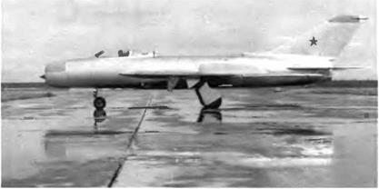
The I-7U interceptor equipped with the Uragan-1 was developed once it became apparent that the I-3U would be grounded for lack of the right engine. The preliminary plans were completed in August 1956. The structure of the new aircraft was entirely reworked so that it could be powered by the Lyulka AL-7F turbojet, which delivered a dry thrust of 6,155 daN (6,240 kg st) and a reheated thrust of 9,035 daN (9,220 kg st). Except for a few standardized parts, the only piece of equipment common to both the I-3U and the I-7U was the Uragan-1 system Everything else was completely modified.

All of the main airframe assemblies were redesigned after recon­sideration of their basic principles. The fuselage diameter was increased, the wing sweepback С/4 was reduced to 55 degrees, and the gear kinematics were modified (the main gear retracted into the fuse­lage, their legs folding up inside the wing between the integral fuel tanks and the Fowler-type flaps). Many stamped panels were required for the wing and the tail unit The ailerons and other movable surfaces contained no ribs but rather a solid core. Armament comprised two NR-30 cannons located on either side of the fuselage alongside the wing root ribs and four optional automatic rocket pods under the wing with a total of sixty-four ARS-57M rockets.

The aircraft was moved to the test center on 26 January 1957 and on 17 April performed its first taxiing tests, during which the aircraft was lifted a few feet. The I-7U made its first flight on 22 April with G. K. Mosolov at the controls. On the thirteenth flight the landing gear on the right side collapsed as the aircraft landed, damaging the right wing. The aircraft was returned to the workshop for repairs and later made six more flights, the last one on 24 January 1958. On 12 February tests were canceled by the general designer. The aircraft was once more returned to the workshop; fitted with the AL-7F-1 engine, it became the 1-75F.

The tests had demonstrated the aircraft’s quick acceleration as well as its outstanding climb rate on either dry or reheated thrust, a distinc­tive feature of the 1-7U. On the other hand, the deflection travel of the stabilator proved to be sufficient at landing. When the aircraft reached Mach 1.6-1.65 it had a tendency to bank to the left, but its yaw stability remained satisfactory.

The resemblance between the 1-7U and the I-3U was quite superficial. The I-7U was in feet an entirely new machine.

The weapons system was the only common feature of the I-7U and I-3U The cone housing the Almaz ranging radar is centered on the I-7U.

256

Specifications

Span, 9.976 m (32 ft 8.7 in); overall length, 16.925 m (55 ft 6.3 in); fuse­lage length (except cone), 15.692 m (51 ft 5.8 in); wheel track, 3.242 m (10 ft 7.6 in); wheel base, 5.965 m (19 ft 6.9 in); wing area, 31.9 mz (343.4 sq ft); empty weight, 7,952 kg (17,525 lb); takeoff weight, 10,200 kg (22,480 lb); max takeoff weight, 11,540 kg (25,435 lb); fuel, 2,000 kg (4,410 lb); wing loading, 319.7-361.7 kg/m2 (65.5-74.1 lb/sq ft); max operating limit load factor, 9.

Performance

Recorded max speed with engine dry rating, 1,420 km/h (767 kt) (not recorded with reheated thrust because the Pitot-static probe readings were not corrected at high speeds; the max speeds that follow are design specifications); max speed with reheated thrust, 1,660 km/h at

5.0 m (896 kt at 16,400 ft); 2,200 km/h at 10,000 m (1,188 kt at 32,800 ft); 2,300 km/h at 11,000 m (1,242 kt at 36,080 ft); climb to

5.0 m (16,400 ft) in 0.6 min; to 10,000 m (32,800 ft) in 1.18 min; ser­vice ceiling, 19,100 m (62,650 ft); landing speed, 280-300 km/h (150-162 kt); endurance, 1 h 47 min; range, 1,505 km (935 mi); takeoff roll, 570 m (1,870 ft); landing roll, 990 m (3,250 ft).

Ye-GV

Two Tip 74 airframes, the Ye-6V/1 and Ye-6V/2, were modified to assess various positions for the tail chute container, to test several types of chutes, and to make jet-assisted takeoffs with solid propellant rockets. The Ye-6V had two tail chute canisters, one on the left side of the ventral fin and the other at the base of the tail fin. The latter posi­tion was retained on all MiG-2 Is starting with the PFM Both Ye-6V prototypes were also tested with wheel-ski compound gear Fedotov demonstrated jet-assisted takeoffs in the Ye-6V/2 at the Tushino air show on 9 July 1961.

MiG 211 / 2111 / Analog

Two MiG-21Is were built to test the wing scheme of the Tu-144 supersonic airliner

The airframe of the test bed was that of a MiG-21S fitted with a compound sweepback delta wing (78 degrees at the wing root over one – third of the leading edge, then 55 degrees) Its thickness-chord ratio tapered from 2 3 percent at the wing root to 2 5 percent at the wing tip The trailing edge was shared evenly by the flaps and elevons The plan view of the wing was almost identical to that of the Tu-144—hence the nickname “Analog"

Two MiG-21Is were needed for research purposes No. 1 was first piloted by О V. Gudkov on 18 April 1968, and the flight tests continued for about one year Unfortunately, just after completion of the basic tests the prototype was destroyed. No 2 was kept airworthy for several years. Both MiG-21Is were powered by the R-13F-300 capable of 6,360 daN (6,490 kg st) The total capacity of the fuel tanks was 3,270 1 (864 US gallons). Both aircraft were used to train the first two pilots of the Tu-144, E Yelyan and M Kozlov

Specifications

Span, 8.15 m (26 ft 8.9 in); length (except probe), 14.7 m (48 ft 2 8 in), fuselage length (except cone), 12.287 m (40 ft 3.7 in), wheel track, 2 787 m (9 ft 1 7 in), wheel base, 4.71 m (15 ft 5.4 in); wing area, 43 m2 (462 85 sq ft); takeoff weight, 8,750 kg (19,285 lb); fuel, 2,715 kg (5,985 lb); wing loading, 203 5 kg/m2 (41.7 lb/sq ft).

342

MiG-211 Analog; the fairing atop the fin contained a camera (MiG OKB three-view drawing)

The MiG-21 PD was an experimental STOL aircraft developed from a MiG-21 PFM air­frame that was extended by 900 millimeters (35 4 inches)

Performance

Max speed, Mach 2 at 13,000 m (42,640 ft); max speed at sea level, 1,200 km/h (648 kt); landing speed, 225 km/h (122 kt).

SVUG-25P / Ye155P / HG-25PD / MiG25PDS / §4

The Ye-155P high-altitude supersonic interceptor project was con­firmed by a decree of the council of ministers in February 1962 But in fact the ОКБ had started the preliminary design two years earlier Con­trary to what was thought, the project was not intended to face the

Canard surfaces could be affixed to the auxiliary structures located near the top of the air intake duct on the Ye-155P prototype of the MiG-25P, The wing pylons held R-40 air-to-air missiles.

threat represented by the American XB-70 Walkyrie Mach 3 bomber. Instead, it was a response to the Lockheed A-l 1.

By listing all of the advancements that the MiG-25 was about to inherit, its technical evolution can be better appreciated:

—a weapon system capable of intercepting any type of flying target, from cruise missiles at low altitudes to supersonic aircraft at veiy high altitudes

—a structure permitting the interceptor to break the heat barrier and fly long supersonic dashes

—high lift-to-drag ratio, good stability, and sharp maneuverability across a wide flight envelope where speed and ceiling were usual­ly favored

—a new (for MiG) aerodynamic scheme with lateral air intakes, twin fins, and two ventral fins

—a structure in welded steel that featured high mass ratio, simple maintenance, good manufacturing regularity due to automation, high output factor for the materials, and lower production costs due to better productivity

One of the seven preproduction MiG-25s fitted with triangular winglets and antiflutter bodies at the wing tips. The wing had no anhedral.

—electronic fuel control (the first in the USSR) and a single refueling point

—a greater number of auto-flight control modes with (for the first time) a range of programming possibilities: for altitude, flights on preset paths, landing approaches, limitations in automatic or semiautomatic flight modes, and overspeed warning —utilization of new materials and semifinished products in high – strength steel, titanium, and heat-resistant duralumin —intensive employment of automatic control systems and flight data recorders

—new technological processes for the heat treatment of materials to alleviate strains and stresses, plus new control and maintenance practices

—a long lifetime and time between overhauls for a combat aircraft of this category

The Ye-155P-l prototype was powered by two Mikulin-Tuman – skiy R-15B-300 turbojets originally rated at 7,350 daN (7,500 kg st) dry and 10,005 daN (10,210 kg st) with afterburner. Its main elements were developed on the R-15-300 that powered the Ye-150 experimen­tal aircraft. Unfortunately, its service life was limited to 150 hours.

The MiG-25PD was equipped with the new RP-25 radar and four pylons under the wing for two R-40 and four R-60 air-to-air missiles.

The internal fuel capacity was considerable: 17,760 1 (4,689 US gal­lons) distributed across built-in tanks in the fuselage and wing. The air inlet control was secured by a small rectangular flap in the lower lip of the air intake and by an internal door (both actuated by elec­tronically controlled cylinders). There was a spill door in the upper panel of the air intake duct, and both turbojets were equipped with adjustable-area nozzles.

If one overlooks the materials and the production processes, the wing had a standard box structure with two main spars attached to fuselage bulkhead nos. 7 and 9, a front spar fixed to the no. 6B frame, and two rear spars fastened to bulkhead nos. 10 and 11. The hinge pin for the flaps was also fixed to bulkhead no. 11. The plain flaps occupied one-third of the trailing edge, as well as the two-section ailerons that measured 2.72 m2 (29.28 square feet). There were two fences on the upper surface of each wing: one as long as the wing chord, roughly along the aileron/flap separation line; the other much smaller, along the aileron sections’ separation line. The wing leading edge had a com­pound sweepback: 42 degrees, 30 minutes at the wing root on half of the LE span, then 41 degrees. On the P-1 prototype the wing had nei­ther dihedral nor anhedral, and the wing tip was fitted with downward – canted winglets. The wing structure was made of welded steel, and its

Hie nose of the MiG-25PDS was lengthened by 250 millimeters (9.84 inches) to house the in-flight refueling probe. The added “slice" can be seen to the right of the “45." skin was made partly of titanium (especially on the leading edge) and partly of D19 duralumin.

The structural backbone of the fuselage consisted of fourteen bulk­heads (the first one level with the cockpit windshield, nos. 13 and 14 supporting the stabilator fulcrum pins on either side of the engine noz­zles) and many frames and stringers. The air intake ducts were not added up but were built-in members. The nose, made of nonconduc – tive material, housed the dish antenna for the Smerch-A ("whirlwind") radar, which could automatically lock on and track aerial targets within 50 km (31 miles). Behind the radar was the electronics compartment and the cockpit, whose canopy was hinged to open starboard. The inner walls of the air intake duct were separated from the fuselage to form a boundary layer bleed.

The airbrakes were located at the rear of the fuselage astride the engine nozzles, one atop the fuselage immediately ahead of the tail chute canister and one underneath it; they fit the curves of the nozzle closely. Both landing lights retracted into the lower wall of the air intake ducts. The tail unit comprised two fins canted outward (11 degrees) and a slab tailplane (sweep of 50 degrees at the leading edge and 9.81 m2 [105.6 square feet] in area). Two large ventral fins—whose size was later reduced—were located under the engine nozzles. On the prototypes a canard surface could be installed on either side of the air intake duct to act as a destabilizing device on some flight regimes This strategy was tested on the Ye-8 The tricycle gear consisted of a twin wheel forward-retracting nose unit and a single wheel with high-pres- sure tires 1 3 m (51 2 inches) in diameter on each forward-retracting mam unit Those wheels were stowed vertically in the side walls of the air intake duct

Though it was designed first, the Ye-155P-l made its premier flight after the Ye-155R-1 reconnaissance variant. Engineers took advantage of the knowledge acquired during the R-l flight tests to make a number of modifications

—the canard surface was discarded as useless

– the area of the fins was increased significantly to 8 m2 (86.1 square feet) apiece

—the chord of the ventral fins was reduced subsequently (they tend­ed to touch at landing)

—the winglets were removed, but the wing tips were fitted with an antiflutter body

—the wing was given a 5-degree anhedral (before that modification seven preproduction machines had triangular end plates at the wing tips)

—after the displacement of its fulcrum pms, the slab tailplane had a taileron capability at high speeds meaning that the two halves could operate in unison (for pitch) or differentially (for roll)

All of these modifications increased the maximum indicated air­speed to 1 300 km/h (702 kt) As was standard practice for new aircraft the ОКБ tried hard to improve its operational availability, service life, and time between overhauls

The Ye-155P-l was first piloted by Ostapyenko on 9 September 1964 (six months after the Ye-155R-1) but was not certified until 1970; it entered service with the WS only in 1973, though mass production had started four years earlier The official decree by the council of min­isters commissioning the aircraft for the Soviet air force was signed on 13 April 1972 Close scrutiny of those dates indicates that the MiG-25 suffered repeatedly from childhood diseases This is not surprising in view of the project’s many innovations There were problems with the stabilator in its taileron mode. There were problems with the ailerons There were problems with the dangerous asymmetry noticed at high speeds whenever a single missile was fired from a wing station Auto­matic trim resolved the taileron shortcomings, and all others were set­tled by V Gordyenko, the LII test pilot There were also concerns about engine TBO that could not be solved—for want of money

The Ye-155P-l prototype was armed with two R-40 air-to-air mis­siles, but the production M1G-25P could carry four of them plus two infrared-guided R-40Ts and two radar-guided R-40Rs. Its primary equip­ment included the Smerch-A radar and the K-10T associated weapon pointing device, the SOD-63 АТС transponder, the SRO-2M/SRZO-2 IFF (transponder/interrogator) whose antennae were flushed in the starboard fin, the Sirena-3 360-degree radar warning receiver whose antennae were set into the center of the antiflutter bodies at the wing tips and at the top of the starboard fin, the RV-UM or RV-4 low-altitude radio-altimeter for 0-600 m (0-1,970 feet), the ARK-10 automatic direc­tion finder, the MRP-56P marker receiver, the SP-50 ILS, the RSBN-6S short-range navigation unit, the R-832M VHF-UHF transceiver, the Prizma HF transceiver, the Lazur command receiver, and the SAU-155 automatic flight control system. The ejection seat was the KM-1 (alti­tude, 0 m; speed, 130 km/h [70 kt]). The МЮ-25Р had two tail chutes with either a circular (60 m2 [646 square feet]) or a cross-shaped canopy (50 m2 [538 square feet]).

Taking into account the experience acquired in the air regiments as well as technological advances, a new version of the aircraft entered production in 1978: the MiG-25PD. It used a new power plant com­posed of two R-15BD-300s—each rated at 8,625 daN (8,800 kg st) dry and 10,975 daN (11,200 kg st) with afterburner—whose service life was extended in stages to 1,000 hours. The Smerch-A radar was replaced by the Sapfir-25 (RP-25), which offered better performance in the automat­ic tracking mode and true look-down/shoot-down capabilities. The MiG-25PD’s armament was supplemented, comprising now two R-40 and four R-60 air-to-air missiles. Infrared sensors were placed under the forward section of the fuselage. The range was increased signifi­cantly by an auxiliary tank attached to the underbelly (developed for the Ye-155R) that could hold 5,300 1 (1,400 US gallons).

As of 1979 all operational MiG-25Ps were upgraded to the MiG – 25PD standard as quickly as they could be sent to overhaul workshops. These modified aircraft received the appellation MiG-25PDS. The MiG – 25PD was mass-produced until 1982. Thanks to the weapon system modifications and improvements to the airframe and engine TBOs, the PVO command announced in 1990 that the MiG-25 would be still oper­ational at the start of the next millennium. The MiG-25 was exported to Algeria, Iraq, Libya, and Syria.

The following details refer to the MiG 25P.

Specifications

Span, 14.015 m (45 ft 11.8 in); length (except probe), 19.75 m (64 ft 9.6 in); wheel track, 3.85 m (12 ft 7.6 in); wheel base, 5.139 m (16 ft 10.3

393

МІС-25Р (MiG ОКБ three-view drawing)

in); wing area, 61 4 m2 (660.9 sq ft); takeoff weight with four R-40 mis­siles and 100% internal fuel, 36,720 kg (80,930 lb); takeoff weight in clean configuration with 100% internal fuel, 34,920 kg (76,965 lb); fuel, 14,570 kg (32,110 lb); with 5,300-1 (1,400-US gal) auxiliary tank, 18,940 kg (41,745 lb); wing loading, 598-568.2 kg/m2 (122.6-116.5 lb/sq ft); max operating limit load factor at supersonic speed, 4.5.

Performance

Max speed, 3,000 km/h at 13,000 m (1,620 kt at 42,640 ft); max speed at sea level, 1,200 km/h (648 kt); max Mach number, 2.83; climb to 20,000 m (65,600 ft) in 8.9 min at Mach 2.35; service ceiling, 20,700 m (67,900 ft); landing speed, 290 km/h (157 kt); takeoff speed, 360 km/h (194 kt); range on internal fuel at supersonic speed, 1,250 km (775 mi); at subsonic speed, 1,730 km (1,075 mi); endurance on a coverage mission, 2 h 5 min; takeoff roll, 1,250 m (4,100 ft); landing roll with tail chute, 800 m (2,625 ft).

IVHG 29KVP МШ-29К / 9-31

In the early 1980s the Soviet Navy announced its desire to equip its future cruisers-aircraft carriers* with highly maneuverable, well – armed supersonic fighters. This aircraft type was to have the opera­tional radius to intercept and destroy airborne invaders as far away from its floating base as possible and to be capable of short takeoffs at full load. The OKB engineers and pilots under the leadership of M. R Valdenberg thought that their best choice for this project was to "naval – ize” the MiG-29 airframe, and they transformed it into a proof-of-con – cept aircraft.

The essential modifications concerned the gear, which was strengthened to withstand higher sink rates at touchdown, and the tail section of the fuselage, which was reinforced to receive an arrester hook. The new aircraft was named MiG-29KVP (Korotkii Vzlet •This shrewd label authorizes the carrier to proceed through the Dardanelles. As “car­rier” alone, she could not pass in accordance with international agreements and would therefore be trarmed in the Black Sea.

MiG-29K no. 311 lands on the deck of a carrier It is just about to catch the first arrest­ing cable with its hook.

The wing’s folding axis runs between the flaps and the ailerons. Structural modifica­tions were reduced to the bare essentials

A MiG-29K takes off from the aircraft carrier’s deck in fewer than 100 m (300 feet) thanks to the ski-jump technique and the special booster regime of its RD-33K turbo­fans

The MiG-29KVP was a proof-of-concept aircraft used to prepare the design and devel opment of the MiG-29K.

The M1G-29K is fitted with a retractable refueling probe

і Posadka. short takeoff and landing, or STOL) and was first piloted by Fastovets on 21 August 1982. A long test campaign then began, lead­ing to the conclusion that to fulfill all its requirements the aircraft needed a greater wing area, more efficient lift devices, more powerful engines, and a far greater fuel capacity Since the OKB was concur­rently developing the 9-15 project (the future MiG-29M), which met most of the requirements, it was decided to develop the naval aircraft from that airframe.

Like the MiG-29KVP, the modifications for this new project con­cerned the strengthening of the long-stroke gear (shortening links on the main gear legs) and the reinforcement of the rear section of the fuselage to receive the arrester hook (entailing the removal of the brake chute). In addition, engine thrust was boosted at takeoff thanks to the ChR system, and the wing had to be thoroughly redesigned. The wing area of the MiG-29M still fell short of the navy’s needs, so the wing chord was extended ahead of the leading edge by adding a front

The second prototype of the MiG-29K with its full external armament four R-73A short-range air-to-air missiles and four Kh-31P long-range air-to-surface missiles

spar to support the two-segment LE flaps; also, the wing flaps were extended beyond the trailing edge, and the ailerons were shortened. That is how the wing area was increased by 3.6 m2 (36.6 square feet). The wing was also made foldable (the fold axis lies between the aileron and the flap).

The wing tips were bulged to house electronic support measures (ESM) equipment. Because the danger of ingesting foreign objects on takeoff and landing is practically nonexistent on a carrier, the overbody louvers were deleted and the multisegment ramp system was readjust­ed; but to prevent seabirds from being sucked in, the air intakes are still equipped with lightweight deflector grids that can be retracted in flight. Due to the special nature of the environment in which the air­craft would operate, engineers had to take exceptional anticorrosion measures, make sure all bays and access doors sealed tightly, and include the stowage devices usually found on carrier-based aircraft.

The 9-31, renamed MiG-29K (Korabelniy: ship-based), is, like the MiG-29M, powered by two RD-33K turbofans rated at 8,625 daN (8,800 kg st). When taking off in a fully loaded aircraft, the pilot can use a spe­cial afterburning rating similar to the ChR (Chrezvichaimy Rezhim exceptional rating) used on the MiG-21 SMT and MiG-21bis that adds 588 daN (600 kg st) to each engine. The overall fuel capacity is 9,610 1

MiG-29K (MiG OKB three-view drawing)

(2,540 US gallons), and the aircraft is fitted with a retractable refueling probe on the left side of the nose. Like the MiG-29M, the MiG-29K is fit­ted with the N 010 multimode pulse-Doppler radar.

Prototype no. 311 was first flown on 23 June 1988 by test pilot T. Aubakirov at Saki naval airfield on the Crimean Peninsula, where one of the runways was equipped with a ramp very similar to the ski jump of the 65,000-tonne (67,000-ton) aircraft carrier Tbilisi. In November 1989 the aircraft made its first deck takeoffs and landings from that ship, which in the meantime had been renamed Admiral of the Fleet Kuznetsov. It was a great premiere for both the Soviet Navy (VMF) and its aeronautical branch (MA) and was much to the credit of test pilot Aubakirov, who had to use the ski jump of the deck’s forward end instead of the usual carrier catapult to take off.

In 1990 the focus of the tests was the development of an automated landing procedure and the necessary electromagnetic compatibility between the aircraft and the carrier’s radioelectric systems. The second prototype, no. 312, exhibited at Machulishche near Minsk in February 1992, carried four R-73E short-range air-to-air missiles under the wing’s folding panels and four Kh-31P air-to-surface missiles fitted to AKU – 58M ejector pylons under the fixed panels. But it was only one of the many combinations of weapons that the MiG-29K could carry because on the sole export version no fewer than twelve different types of mis­siles are offered: air-to-air missiles, R-73E, R-27R1, R-27T1, R-27E(R), R-27E(T), RW-AE; air-to-surface missiles, Kh-29T, Kh-29L, Kh-25P, Kh – 25ML, Kh-31P, Kh-31A. The aircraft could also carry various types of bombs, including the KAB-500KR "smart’’ bomb, or B-8 and B-13 rocket pods. Its armament contains the GSh-301 (9A4071K) cannon with 100 rounds, located above the port body leading edge.

Specifications

Span, 11.36 m (37 ft 3.2 in); overall length, 17.37 m (56 ft 11.8 in); height, 4.73 m (15 ft 6.2 in), wheel track, 3.09 m (10 ft 1.7 in); wheel base, 3.645 m (11 ft 11.5 in); wing area, 41.6 m2 (447.78 sq ft); takeoff weight in clean configuration, 18,480 kg (40,705 lb); max takeoff weight, 22,400 kg (49,340 lb); wing loading, 444.2-538.4 kg/m2 (90.57-110.27 lb/sq ft).

Performance

Same as MiG-29M, except for: range in clean configuration, 1,600 km (1,000 mi); range with one 1,500-1 (396-US gal) and two 1,150 1 (304-US gal) auxiliary tanks, 2,900 km (1,800 mi).

This wind tunnel model of the MiG-29KU ship-based trainer shows the especially high location of the rear seat.

UTI MiG-15 /1312 / ST

In the MiG-15 test report the Nil WS experts had pointed to the need for a two-seat training version of the aircraft. Because the MiG-15 was mass-produced for the WS, the PVO, and the VMF, a “jet-flying class" had to be developed for the many pilots who had flown only piston – engine aircraft. Decrees from the council of ministers on 6 April 1949 and the ministry of aircraft production on 13 April ordered the MiG ОКБ to design and construct a UTI (Uchebno-trenirovich istrebityel: for­mation and training fighter) by 15 May—that is, in just five weeks! Once the test flights were completed, an entire factory would be dedi­cated to the sole production of the UTI MiG-15.

image126

Armament of the prototype and first-series UTI MiG-15s consisted of one NR-23 can­non and one 12.7-mm UBK-E machine gun.

The aircraft was a straight two-seat modification of the MiG-15 powered by the same RD-45F engine. Both the student in the front seat and the instructor in the rear were in a pressurized cockpit, A reduced armament suite—one machine gun and one cannon—was placed on a removable rack. Both flight stations had fully instrumented panels and first-generation ejection seats (the same as those in the MiG-15). The front-seat instrument panel and equipment were identical to those of the MiG-15 so that the student pilot could become fully acquainted with his environment in preparation for his first solo flight in the sin­gle-seater. With the dual controls, the instructor could always control the aircraft and counteract the student’s mistakes. The front canopy was starboard-hinged, and the rear canopy was rearward-hinged; both could be jettisoned in case of emergency. The rear-seat occupant was ejected first.

For gunnery exercises, the first-series UTI MiG-15s had a 23-mm NR-23 cannon with 80 rounds and a 12.7-mm UBK-E machine gun with 150 rounds. Starting with the sixth series, and after tests with the ST-2, the cannon was replaced on the removable rack by an OSP-48 instru­ment landing system. The student cockpit was equipped with an ASP – IN gunsight. In the front, two armor plates were bolted on frame no. 4—one to protect the crew, and the other to shield the ammunition

Подпись:
boxes and equipment placed on the machine gun rack. The ejection seats were fitted with armored headrests. Two store stations were pro­vided beneath the wing for 50-kg (110-pound) and 100-kg (220-pound) bombs. An S-13 camera gun was added to the upper lip of the engine air intake. Communication equipment included an RSI-6 transceiver, but most UTI MiG-15s were fitted with an RSIU-3 VHF transceiver, an SRO-1 IFF transponder, and an AFA-1M wide-angle camera. From air­craft no. 10444 onward armament was reduced to a single UBK-E 12.7, and the ASP-1 N gunsight was replaced by an ASP-3N; but the fire con­trol and bombing systems were identical to previous versions. All UTI MiG-15s also had electrically operated flare launchers, one for each of four colors: red, green, white, and yellow.

The ST was built in the OKB experimental workshop between March and May 1949, using a MiG-15 airframe built in Kuybyshev fac­tory no. 1. It underwent factory tests from 23 May to 20 August 1949 under the supervision of three pilots: I. T. Ivashchenko, К. K. Kokkina – ki, and A. N. Chernoburov. State acceptance trials took place at the GK Nil VYS from 27 August to 25 September, and mass production was approved. The prototype was sent to a fighter regiment in Kubinka from October 1949 to April 1950, when it returned to the OKB for the adjustments needed to eliminate the shortcomings recorded in opera­tion. On 15 May it passed the final factory tests administered by Cher­noburov and S. Amet-Khan of the LII. In a little over a year the proto­type made 601 flights—33 in factory tests, 58 in state trials, 502 in a fighter regiment, and 8 more back at the factory.

As early as 1952 there were in practice four UTI MiG-15s in every fighter regiment equipped with MiG-15s. Besides their normal role as
pilot trainers, they were also used to make weather reconnaissance flights and to teach pilots how to fly at night and under adverse weath­er conditions. To this end, the front cockpit was equipped with a cur­tain so that pilots could train for blind flying in the daytime. The air­craft was also used to train pilots for dive-bombing and photo recon­naissance missions.

From the outset, MiG-15s equipped with the older ejection seats were not popular: many pilots were afraid to risk serious injury by using the seat in emergencies. After all, most accidents happen when flying near the ground at minimum control speeds or when landing— and in those situations use of the first-generation seats was risky. This fear presented a psychological obstacle that had to be overcome in order to restore the airmen’s confidence. So it was decided that some of the UTI MiG-15s would be used as ejection trainers. Military instructor parachutists went to WS and PVO fighter regiments and demonstrated ejections above each unit airfield. Then they asked for volunteers among the regiment’s pilots. These volunteers were ejected from the aircraft’s rear seat. The seat carried a reduced pyrotechnic charge, but one still powerful enough to catapult the seat—and its contents—above the aircraft’s fin.

The UTI MiG-15 was mass-produced in the USSR, Czechoslovakia, Poland, and China. Czechoslovakia alone built 2,012 of them (referred to as the CS-102). They have been operational for more than thirty years and have trained all MiG-15, MiG-17, and MiG-19 pilots. In the early 1970s nearly all of the UTI MiG-15s still active in the WS and the PVO were handed over to the DOSAAF (the voluntary association for the support of the army, the air force, and the fleet). That kept the two- seaters in the air for a few more years with pilots from various Soviet flying clubs in the cockpit.

Specifications

Span, 10.085 m (33 ft 1 in); overall length, 10.11 m (33 ft 2 in); fuselage length, 8.08 m (26 ft 6.1 in); height, 3.7 m (12 ft 1.7 in); wheel track, 3.81 m (12 ft 6 in); wheel base, 3.175 m (10 ft 5 in); wing area, 20.6 m2 (221.7 sq ft); empty weight, 3,724 kg (8,208 lb); takeoff weight, 4,850 kg (10,690 lb); takeoff weight with two 260-1 (69-US gal) auxiliary tanks, 5,320 kg (11,725 lb); takeoff weight with two 300-1 (79-US gal) auxiliary tanks, 5,400 kg (11,900 lb); fuel, 900 kg (1,984 lb); useful load (fuel, ammunition, crew), 1,588 kg (3,500 lb); wing loading, 235.4-262.1 kg/m2 (48.3-53.7 lb/sq ft); max operating limit load factor, 8.

Performance

Max speed, 1,015 km/h at 3,000 m (548 kt at 9,840 ft); 720 km/h at

13,0 m (389 kt at 42,640 ft); max Mach number, 0.894; climb to

image128

The UTI MiG-15P (ST-7) was used to train pilots to operate the RP-1 Izumrud radar.

3.0 m (9,840 ft) in 1.5 min; to 5,000 m (16,400 ft) in 2.6 min; to

10.0 m (32,800 ft) in 6.8 min; service ceiling, 14,625 m (47,970 ft); landing speed, 172 km/h (93 kt); range, 680 km at 5,000 m (422 mi at 16,400 ft); 950 km at 10,000 m (590 mi at 32,800 ft); range with two 300- 1 (79-US gal) auxiliary tanks, 1,054 km at 5,000 m (655 mi at 16,400 ft), 1,500 km at 10,000 m (930 mi at 32,800 ft); takeoff roll, 510 m (1,675 ft); landing roll, 740 m (2,425 ft).

MiG-17F / SP-2

The focus of this program was the performance of the RP-3 Kor – shun ("kite") ranging radar designed by the Slepushkin OKB. The Kor- shun-equipped MiG-17F was built in response to two directives from the USSR council of ministers, dated 10 June 1950 and 10 August 1951. These directives called for the development of a fighter “to intercept and destroy, day or night and whatever the weather conditions, any enemy bomber, reconnaissance aircraft, or escort fighter." The Kor – shun ranging radar used a Cartesian-coordinate scanning mode.

The SP-2, derived from the SI-2, differed from the basic MiG-17F in the following ways:

1. The fuselage nose section had to be modified

2. The N-37D cannon was removed, but the ammunition reserve for

image166

The SP-2 was an experimental variant of the MiG-17F intended to assess the perfor­mance of the Korshun radar.

the remaining NR-23 guns was increased to 90 and 120 rounds, respectively

3. Several systems were relocated

4. The airbrakes opened automatically at M 1.03 and retracted as soon as the aircraft’s speed dropped to M 0.97 (and they could still be operated manually)

5. The camera gun was moved to the right side of the engine air intake

6. The capacity of the rear fuselage tank was increased to 250 1 (66 US gallons) from 195 1 (51 US gallons)

G. A. Sedov conducted the factoiy tests between March and Nov­ember 1951. State acceptance trials were carried out from 28 Novem­ber to 29 December by Nil WS and PVO military pilots such as A. P. Suprun, Yu. A. Antipov, V. G. Ivanov, Ye. I. Dziuba, Ye. Ya. Savitskiy, and R. N. Sereda. Experiments with the Korshun radar proceeded in July and August 1951 on an 1-320 fighter prototype. The Korshun was basically a modified rendition of the Toriy-A, which was tested from February to May 1950 in an SP-1. Neither radar could operate in an automatic tracking mode.

image167

The SM 1 is in fact the MiG-15 bis 45 reengmed with two Mikulin AM 5As These tur bojets were later fitted with afterburners and renamed AM-5F


image168

Specifications and Performance of the SP-2

Specifications and performance

Design

requirements

SP-2

Takeoff weight

5,320 kg (11,725 lb)

Fuel capacity

1,510 1 (399 US gal)

Maximum speed

At 3,000 m (9,840 ft)

1,109 km/h (599 kt)

At 5,000 m (16,400 ft)

1 094 km/h (591 kt)

1,097(592)

At 10,000 m (32,800 ft)

1,042(563)

1,046 (565)

At 12,000 m (39,360 ft)

1 022 (552)

1,020(551)

Maximum Mach number

1.03

Climb

To 5,000 m (16,400 ft)

2 mm

2 min

To 10,000 m (32,800 ft)

5 1

5.2

Service ceiling

15,600 m (51,170 ft)

15,200 m (49,860 ft)

Range at 12,000 m (39,360 ft)

Without drop tanks

1,300 km (805 mi)

1,375 km (855 mi)

With drop tanks

2,500 (1,550)

2,510 (1,560)

Armament

2 x NR-23

2 X NR-23

Ammunition

90 + 120 rounds

Source: MiG OKB

The following extract from the final test report is especially note­worthy:

1. The SP-2’s performance meets the targets stipulated in the direc­tives of the USSR council of ministers

2. The SP-2’s performance data are almost identical to those of the MiG-17F

3. The aircraft’s combat capabilities are limited because it is diffi­cult for the pilot of a single-seater to follow up the Korshun data (searching for, approaching, and sighting the target) for several reasons: first, it is impossible to determine with sufficient accura­cy the distance between the fighter and its target; second, it is impossible to reduce the aircraft’s speed quickly when approach­ing the target because of the poor efficiency of the airbrakes; and third, the radar is not very reliable

4. Taxiing and taking off with two 600-1 [158-US gallon] drop tanks is rather tricky because of the aircraft’s inertia

For these and other reasons the Nil WS put an end to the Korshun research program. The table above is quite noteworthy because it allows us to compare the design performance data outlined in the gov­ernment directives with those of the SP-2

MiG -1ЯР / SM 7

Another derivative of the SM-2, this tactical interceptor was designed for day, night, and bad weather use The SM-7 differed from the SM-9 in many points:

—it was fitted with the RP-1 radar linked to the ASP-5NM gunsight, an IFF interrogator, and a radar warning receiver

—the radio racks were rearranged, and the radar was housed sepa­rately in a more accessible bay

—armament was reduced to two NR-23 cannons in the wing roots, and the ammunition belts (up to 120 rpg) were placed in wing leading edge ducts

—from the start, it was expected that NR-30 cannons would replace the NR-23s

image205

The SM-7/1, an interceptor developed from the SM-2, was equipped with the RP-1

radar.

image206

The SM-7/1 as well as the SM-9/1 had a fixed stabilizer One of the two radio-altime­ters is visible under the right wing

image207

The SM-7/2 as well as the SM-9/3 had a slab tail plane.

image208

The slab tailplane or all-flying tail of the SM 7/2 at its maximum pitch-up deflection.

image209

The SM-7/2—the future MiG-19P—with all of its three airbrakes deployed.

—two RO-57-8 rocket pods with eight ARS-57 rockets apiece could be attached to wing pylons, as well as two 760-1 (201-US gallon) underslung tanks

—the underslung tanks could be replaced by two additional rocket pods with sixteen ARS-57 rockets apiece —because of the radar antennae, the forward section of the fuselage had to be modified up to the no. 9 frame and lengthened by 360 millimeters (14.17 inches)

—the air intake ducts were reshaped accordingly, and their section was enlarged

—both wing tips were fitted with Pitot-static probes, the one on the right linked to the navigational instruments and the one on the left to all the others

—because of the changes made to the forward section of the fuse­lage, it was possible to widen the cockpit —the pilot had a curtain-type ejection seat whose height could be adjusted to three positions over a range of 120 mm (4.7 inches) —the seat back had a 16-mm-thick armor plate behind the rails of the ejection system, which were protected (as was the locking pin of the ejection pyrotechnic system) against shrapnel and even direct hits

—the control rods actuated by the column were moved to beneath the cockpit floor

—ventilation of the adjustable-area nozzle was improved by modify­ing the cooling air supplies

—the RSIU-3 VHF and the ARK-5 automatic direction finder were linked to a single antenna on the fuselage —the DGMK-5 gyroscopic compass and the ARK-5 ADF shared a common indicator on the instrument panel —the oxygen supply for the pilot was increased to five 2-1 (0.53-US gallon) spherical bottles

The first SM-7, powered by two Mikulin AM-9Bs (RD-9Bs) with rated thrust of 3,185 daN (3,250 kg st) each, rolled out of the factory in July 1954 and made its first flight under V. A. Nefyedov on 28 August. Factory tests lasted until 15 December; ОКБ pilots made forty-three flights for a total of twenty-five hours and thirty-six minutes. The air­craft was then moved to the Nil WS, where it was certified. It was mass-produced from 1955 and delivered to WS, PVO, and VMF units under the military designation MiG-19P.

Following the production of the MiG-19S with a slab tailplane, the OKB built the SM-7/2 in 1955. This second prototype was also equipped with a slab tailplane and had the same equipment as the SM-7. It was tested, certified, and mass-produced as well.

Development of the SM-7 and SM-9/1 was basically the work of A. G. Brunov, deputy chief constructor; V. A. Arkhipov, Yu. A. Korolyev, and A. N. Soshin, main constructors; and G. Ye. Lozino-Lozinskiy, R. A. Belyakov, K. N. Rozanov, A. A. Nefyedov, Ya. I. Seletskiy, and N. I. Andrianov, brigade heads.

Specifications

Span, 9 m (29 ft 6.3 in); fuselage length, 10.48 m (34 ft 4.6 in); height, 4.02 m (13 ft 2.3 in); wing area, 25 rrr’ (269 sq ft); empty weight, 5,468 kg (12,050 lb); takeoff weight, 7,384 kg (16,275 lb); takeoff weight with two 760-1 (201-US gal) drop tanks, 8,738 kg (19,260 lb); fuel, 1,700 kg (3,750 lb); wing loading, 295.4-349.5 kg/m2 (60.6-71.6 lb/sq ft); max operating limit load factor, 7.95.

Performance

Max speed, 1,370 km/h at 10,000 m (740 kt at 32,800 ft); 1,255 km/h at 14,700 m (678 kt at 48,200 ft); max speed without reheat, 1,083 km/h at 10,000 m (585 kt at 32,800 ft); max Mach number, 1.384 at 9,800 m (32,150 ft), 1.296 at 8,700 m (28,540 ft); max speed at 1,200 m (3,940 ft), 1,180 km/h (637 kt); climb to 10,000 m (32,800 ft) with afterburner light-up at 5,000 m (16,400 ft) in 1.85 min; to 15,000 m (49,200 ft) with afterburner light-up at 5,000 m (16,400 ft) in 3.8 min; climb to 10,000 m (32,800 ft) without afterburner in 2.25 min; to 15,000 m (49,200 ft) in 6.1 min; service ceiling with afterburner, 17,600 m (57,700 ft); with­out afterburner, 16,150 m (52,970 ft); with afterburner and two 760-1 (201-US gal) drop tanks, 16,000 m (52,500 ft); range, 1,474 km at 12,000 m (915 mi at 39,360 ft); with two 760-1 (201-US gal) drop tanks, 2,318 km (1,440 mi).

175

The 1-75 supersonic interceptor was a direct descendant of the I-7U equipped with the more sophisticated Uragan-5 interception system. The operation of the Uragan-5B modified radar was identical to that of the Izumrud or Almaz except for one thing: it had only one transmit­ter, one antenna, one display system, and two operating modes: search and target designation. The Uragan-5 system also comprised the AP-39 Uragan-5V autopilot, the Uragan-5D airborne computer, and the Ura – gan-5T-l radar control unit, plus two K-8 air-to-air missiles that weighed 275 kg (605 pounds) apiece.

This aircraft was engineered to intercept automatically high-alti- tude supersonic bombers day or night or in bad weather and to destroy them as far away as possible from their intended targets. With two drop tanks its tactical radius of action was 720 km (447 miles). It could attack enemy aircraft at speeds between 800 and 1,500 km/h (432 and 810 kt) and altitudes between 10,000 and 20,000 m (32,800 and 65,600 feet). Its radar detection range was 30 km (18.6 miles), and it could lock onto targets 20 km (12.4 miles) away.

The 1-75 differed from the 1-7U in its forward fuselage, where the Uragan-5 accessory unit was housed. Moreover, in place of cannons it

258

The 1-75 was in fact an I-7U minus the cannons equipped with the new Uragan-5B radar, and armed with two K-8 air-to-air missiles

The I-75’s nose cone is much bulkier than that of the I-7U due to the larger radar antenna.

had wing pods for air-to-air missiles. To increase its efficiency, the fin height was increased and the sweep angle at the leading edge was reduced by 2.5 degrees. The cockpit was equipped with the only type of ejection seat available at MiG at the time. Tail chute canisters were located on either side of the ventral fin. The engine air intake cone was fixed. The air intake duct flow rate was controlled by a translating outer ring on the cylindrical end of the nose cone.

The I-75’s flying controls were of the rigid type (tubular actuating rods in duralumin). The pitch channel was fitted with two BU-44B irre­versible servo-controls and the ARU-3V artificial feel system. The BU – 44 aileron servo-control and the BU-45 rudder servo-control were irre­versible as well. Like the I-7U, the 1-75 was powered by a Lyulka AL-7F turbojet that provided dry thrust of 6,155 daN (6,240 kg st) or 9,035 daN (9,220 kg st) with afterburner. The aircraft was moved to the test center on 1 March 1958 but did not fly until problems in the cockpit ejection system were ironed out.

Watched closely by A. N. Soshm, the chief engineer, G. K. Mosolov made the first flight on 28 April 1958 and four others thereafter. Between 15 May and 24 December the radar was installed and efforts were made to improve the engine and the Uragan-5 system. Flight tests resumed on 25 December and were terminated on 11 May after eigh­teen flights with the radar operating.

Specifications

Span, 9.976 m (32 ft 8.7 in); overall length, 18.275 m (59 ft 11.5 in); fuselage length (except cone), 15.6 m (51 ft 2.2 in); wheel track, 3.242 m (10 ft 7.6 in); wheel base, 5 965 m (19 ft 6.9 in); wing area, 31.9 m2 (343.4 sq ft); empty weight, 8,274 kg (18,235 lb); takeoff weight, 10,950 kg (24,135 lb); max takeoff weight, 11,470 kg (25,280 lb); fuel, 2,000 kg (4,410 lb); oil, 17 kg (37 lb); wing loading, 343.3-359.6 kg/m2 (70.4-73.7 lb/sq ft); max operating limit load factor, 9.

Performance

Max speed, 2,050 km/h at 11,400 m (1,107 kt at 37,400 ft); 1,870 km/h at 12,900 m (1,010 kt at 42,300 ft); 1,670 km/h at 12,400 m (902 kt at 40,670 ft) with two K-8 missiles; design climb to 6,000 m (19,680 ft) in 0.93 min; to 11,000 m (36,080 ft) in 3.05 min; service ceiling, 21,000 m (68,900 ft); landing speed, 240 km/h (130 kt); endurance with after­burner between 10,000 m and 15,000 m (32,800 and 49,200 ft), 25 min; range at 10,000 m (32,800 ft), 1,200 km (745 mi); at 12,000 m (39,360 ft), 1,470 km (910 mi); takeoff roll, 1,500 m (4,920 ft); landing roll,

2,0 m (6,560 ft).

The Ye-150 served as the test bed for the Mikulin-Tumanskiy R-15-300, which would later power the MiG-25