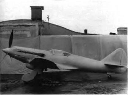
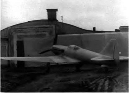
IIIS INTERVIEW WITH U. A. BELYAKOV was conducted and recorded by
Jacques Marmain in Moscow on 6 March 1991.
The MiG OKB celebrated its fiftieth anniversary some months ago. Today you hold the collective memory of this big enterprise, founded at the very moment that World War II broke out. This event having overshadowed the circumstances surrounding the birth of the OKB, can you tell us how all this started?
In early 1939 the threat of war loomed large over Europe and the USSR knew that it would not be spared. Having to face the growing power of Nazi Germany, the Party and the government implemented measures necessary to reinforce the Soviet Army, of which the VVS (air force) was a major component. At this time the lighters in service with our squadrons, the Polikarpov 1-153s and l-16s, were greatly outclassed by the Bf 109Es built by Messerschmitt. There was no time to waste. To create a competitive spirit, several design bureaus were asked to develop and build prototypes. The one with the best flying qualities and combat capabilities was to be mass-produced. Simultaneously, the NKAP (Commissariat of the People for the Aviation Industry) urged the creation of an experimental construction bureau able to attract young, talented specialists.
Which manufacturers were involved in the new program?
There were nine of them: Polikarpov, Yakovlev, and Lavochkin, assisted by Gorbunov and Gudkov, Sukhoi, Borovkov and Florov, Shevchenko, Kozlov, Yatsenko, and Pashinin. All these engineers had to report on their projects personally to Stalin, who was following this program closely. This is why N. N. Polikarpov, chief constructor, P. A. Voronin, manager of the Polikarpov production plant, and P. V. Dementyev, chief engineer, were summoned to the Kremlin in the summer of 1939. The talks were heated. Voronin and Dementyev, supported by Stalin, wanted to give priority to the monoplane, while Polikarpov preferred the biplane for its handling qualities. A work crew was formed within the Polikarpov OKB to create a preliminary design (coded Kh). The crew was composed of a structure specialist, Ya. I. Selyetskiy, an airframe constructor, N. I. Andrianov, and an aerodynamicist, N. Z. Matyuk. These three men are still alive: Selyetskiy is today an assistant to G. Ye. Lozino-Lozinskiy in the space shuttle program, Andrianov is retired, and Matyouk is one of my faithful assistants as chief constructor. The three went to the Kremlin, where Stalin approved the project in the absence of Polikarpov, who was
|
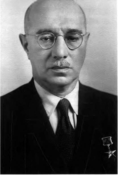
Mikhail Iosifovich Guryevich (1892-1976), Hero of Socialist Labor (1945), doctor of technical sciences (1964), and winner of the Lenin Prize and the USSR State Prize on several occasions.
|
|
then in Germany. You will notice that the name of Mikoyan has not come up yet. There is a very good reason for this: he was not aware of any of these developments. At that time Mikoyan, who was the VVS representative at Polikarpov, was in charge of producing and upgrading the 1-153.
Voronin and Dementyev were the first to believe that Mikoyan was the right man to manage the new team. They confided their thoughts to Stalin, who at first snarled and said, “What! Anastas’s brother!” and then finally agreed—"OK. It’s up to you." The two men did not choose Mikoyan at random. To them, he offered many advantages. They had noticed his spirit, his mind for organization, and his popularity in the VVS and the NKAP, and he was the brother of Anastas Ivanovich Mikoyan, member of the Politburo since 1935 and people’s commissar in various economic commissariats since 1926. But they still had to persuade the surprised Artyom Ivanovich Mikoyan, who finally agreed to this unexpected proposal on one condition: that he could take on his old friend Guryevich as his assistant.
In the meantime, several other engineers had joined the team in November 1939. They all came from the Polikarpov ОКБ: V. A. Romodin, A. G. Brunov, D. N. Kutguzov, and one or two others whose names I have forgotten.
How did the new team succeed in winning its autonomy?
Simply by government decree. But it was quite an event because, with the blessing of the authorities, Voronin and Dementyev exploded the Polikarpov system. The ОКБ, factory no. 1, and the new team were assembled in an OKO, or design and experiment section. A. I. Mikoyan was put in charge of this OKO, assisted by M. I. Guryevich and V. A. Romodin. In November-December 1939 the new OKO attained full strength and submitted the final design of the Kh project renamed the 1-200, which was planned initially with a AM-37 engine. The 1-200 preliminary design was quickly approved by the central committee of the Communist party, the people’s commissariat of the aircraft industry, and the air force. The existence of the OKO was formalized on 8 December 1939.
Could you tell us more about Mikoyan, a man whose name is famous all over the world? We do not really know much about him.
Artyom Ivanovich Mikoyan was born on 5 August 1905 in Sanain, a small Armenian village. His father was a carpenter. He learned to read and write at the village school and then was sent to Tbilisi high school m Georgia.
In 1923 he was admitted to the training school of the Krasniy Aksai factory in Rostov, and the following year he was hired as a mechanic by the railway workshop in the same town. In 1925, still a mechanic, he was employed at the Dynamo factory in Moscow. In December 1928
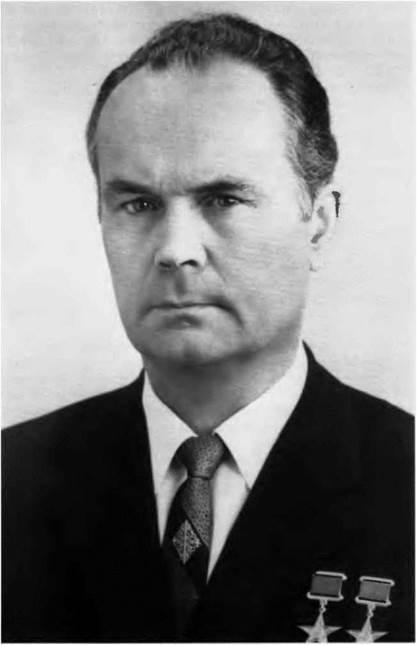
Rostislav Apollosovich Belyakov (1919- ), winner of the Lenin Prize (1972), doctor of technical sciences (1973), member of the USSR Academy of Science (1981), recipient of the A. N. Tupolev Gold Medal (1988), two-time Hero of Socialist Labor, and two – time winner of the USSR State Prize.
he left the factory to do his national service. Discharged two years later, he returned to Moscow and found work at the Kompressor factory He entered the air force academy named after N. Ye. Zhukoskiy in 1931. There things became much more difficult, but young Artyom Ivanovich stuck with it, became keen on parachuting, and learned to fly. In 1935 he and two fellow students used a 22-horsepower American engine to build a light sport aircraft dubbed Oktyabryonok, which apparently was quite a good flier In 1937 he passed his exams at the academy with flying colors and, his first-grade diploma in the bag, found himself representing the military client (in this case, the WS) at the no. 1 Aviakhim factory. The Polikarpov design bureau was located inside this factory, which produced the 1-153 Chaika (seagull) fighters. Mikoyan was in charge of the acceptance checks on behalf of the VYS and then was appointed the permanent representative of the customer within the desrgn bureau. He was therefore in regular contact with Polikarpov, head of the design bureau.
Less than two years later, in March 1939, Polikarpov asked Mikoyan to help him organize and update the Chaika production line. That is where Voronin and Dementyev noticed him. You know what followed.
How was the OKB organized during the first months of its existence?
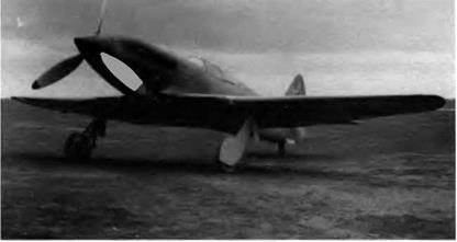
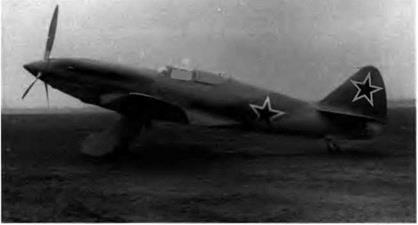
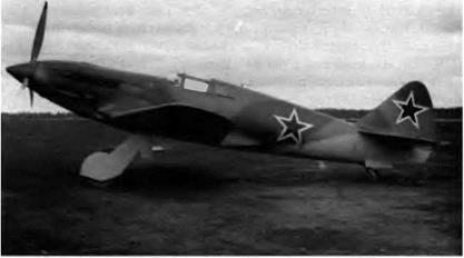
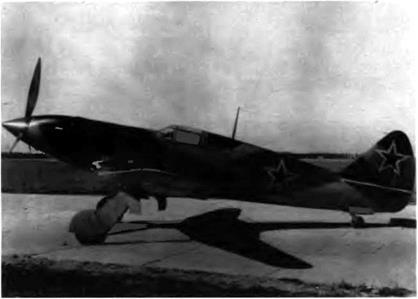
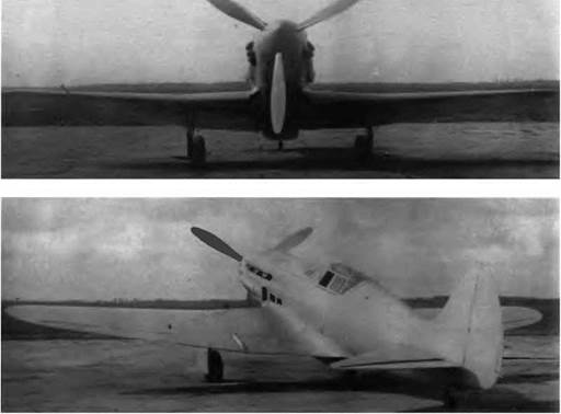
In the beginning, everybody worked like hell at producing all of the drawings for the 1-200 and preparing the assembly of three prototypes. In December 1940 the aircraft received its production designation: MiG-1. The actual assembly of the prototypes began in January 1940, and fewer than a hundred days later, on 30 March, the first machine was moved to the airfield. The first MtG took off on 4 April
In the meantime, in March, Mikoyan was appointed chief constructor at the no. 1 Aviakhim factory, and Guryevich was named deputy chief constructor. The careers of both men developed along the same lines. On 16 March 1942, by decree of the State Commissariat of Defense, the OKO was reorganized within the no. 155 factory, in Moscow—that is, in the very place where we are talking today. Mikoyan became manager and then chref constructor of the new OKB. On 20 December 1956 Mikoyan was appointed general designer, a position that he held until 27 May 1969, when he was struck down by a myocardial infarction. For his part, Guryevich was appointed chief constructor, a position that he retained until he retired in 1964.
Guryevich had by then become no. 2 in the OKB hierarchy. Could you tell us more about his career?
Mikhail Iosrfovich Guryevrch was born in 1892 in Kharkov, a big Ukrainian city. His father worked in a distillery. After finishing high school he entered the advanced mathematics program at Kharkov University but was expelled for taking part in a student revolutionary movement. In 1913 he left for France to study math at Montpellier Uni-
|
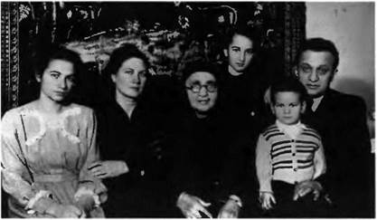
This photograph of the Mikoyan family has never been published before. Right to left: Artyom Ivanovich Mikoyan; Ovanes, his son; Svetlana, his daughter; Talida Otarovna, his mother; Zoya Ivanovna, his wife; and Natasha, his eldest daughter.
|
versify. After the October Revolution he returned to the USSR and resumed his studies at the technological institute in Kharkov. He organized a group of students there into an aeronautics circle that soon became a formal faculty of aviation, and he left in 1925 with a diploma. After working here and there for four years without finding what he was after, he decided to devote all his energies to aviation (his first love), either in a factory or in a design bureau. He spent time in the OKB managed by P. E. Richard, a French engineer who had been invited by the Soviet government to work in the USSR, and in the one headed by S. A. Kocherigin.
In 1937 Mikhail Iosifovich was sent to the United States to negotiate a manufacturing license for the Douglas DC-3 airliner. When he returned to the USSR a year later he took an active part in the preparation of the production line for this aircraft (known here as the PS-84 or Li-2) and the development of new manufacturing techniques. Toward the end of 1938 he joined the Polikarpov design bureau to take charge of the study project department. And that is where Mikoyan noticed him. The loop was looped, and the couple who were to many their initials—MiG—was formed.
If we can trust the morphology of their faces, Mikoyan and Guryevich undoubtedly had very different natures. Could you tell us about these two men as individuals?
You are right. They had very different personalities—but often they complemented one another. Mikoyan was as open, outspoken, and convivial as Guryevich was modest, even unassuming. Mikoyan
took good care of himself; for Guryevich, clothes were the least of his worries. Mikoyan had no experience in aircraft construction. He learned on the job. Because of his great knowledge of common manufacturing problems, he was able to assess a project quickly—and better still, to submit one of his own. Guryevich was erudite, the math expert, the mastermind, who because of his experience and the wide range of his technical knowledge had a talent for drawing up preliminary designs. Without Guryevich, Mikoyan probably would not have succeeded—but the reverse is also true. Guryevich was an engaging person, enamored with literature, always shocked by impurity, impoliteness, and coarseness. He wouldn’t have hurt a fly and was never angry or cross with anyone. He was a married man with no children. Everyone at the design bureau was fond of him, and he proved to be a good social negotiator. Little was heard of him toward the end of his professional life because he was handed responsibility for the “set of themes B,” an innocent name for one of the most secret OKB activities: the development of winged missiles. He retired in 1964 and died of old age in 1976 in Leningrad.
Mikoyan was married and had three children, one son and two daughters. His wife Zoya Ivanovna is still alive. His son, Ovanes Artyomovich, worked at the OKB as an engineer for a long time; he has a passion for sport aircraft and now belongs to the team of Lozino – Lozinskiy.
Some examples of Mikoyan’s other traits are now coming back to me—I offer them to you in a jumble. For instance, he waited on his pilots hand and foot. He loved to take care of people. When the woman in charge of the workers’ council drew his attention to the poor health of the design bureau’s engineers during the war—at this time we seldom got enough to eat—he decided to send us to the country. That is how circumstances led me to make hay, when others organized fishing competitions. We were all able to regain some strength. Mikoyan also liked to fall in with his Armenian friends such as Marshal Bagramian and Tumanyan, Anastas’s brother-in-law. He also struck up friendships with other general designers, including Ilyushin, Tupolev, Yakovlev, and Tumanskiy, an engine specialist who was also a cultured and interesting man.
Mikoyan had a cardiac defect, an abnormal thickness of the pericardium, that caused a lot of problems toward the end of his life. He was strongly affected by the accidental death in 1968 of Gagarin, who was thirty-six at the time, and by the death in April 1969 of Kadomtsev, the PVO commander-in-chief, a man whom he knew well, in a MiG-25 crash. One month later, on 27 May 1969, Mikoyan suffered a stroke that forced him to retire. On 9 December 1970 he had to be sent to the hospital and died on the operating table.
|
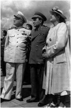
Mikoyan was a friertd of Tupolev, another famous aircraft manufacturer. They are together here during an air show in July 1949. Right, Zoya Ivanovna, Mikoyan’s wife.
|
That very day, you were assigned the heavy responsibility of taking over under difficult conditions. I’m sorry to ask, but you must tell us a little about yourself.
[t is always much easier to talk about others, but as you wish to know every detail, I would have you know that Rostislav Apollosovich Belyakov was bom on 4 March 1919 in Murom, in the Vladimir region. My father was a civil servant. After graduating in 1936 I entered the Moscow Aviation Institute (MAI) named after S. Orjonikidze, where I was taught by such prestigious professors as Yuryev and Zhu – ravchenko. I left with a diploma in 1941 and became an engineer at the MiG OKB. My first task was to work on updating the armament of the MiG-3 under the leadership of Volkov, a weapons specialist of great repute. Soon Mikoyan asked me to work with him and put me in
|
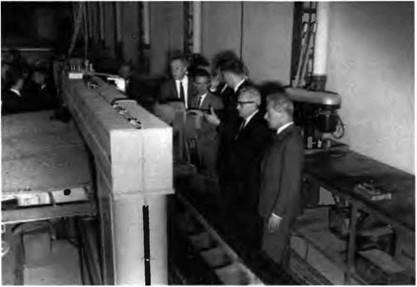
In June 1965 Mikoyan quietly visited the Dassault factory in Talence, France. In the company of Paul Deplante technical manager of the Merignac Dassault factory Mikoyan examines the spot-facing of a Mystere 20 wing socket.
|
charge of the high-lift devices department. In 1955 I was made director of the research department, in 1957 deputy to the chief constructor, and in 1962 first deputy to the general designer. In 1971, a few weeks after Mikoyan’s death, I was named general designer.
As an engineer and a scientist, what are your favorite activities?
I have devoted much of my time and energies to fluid mechanics, aeroelasticity, problems of strength, flight control modes and consequently to flying controls, design of aircraft-plus-missiles systems, power plants, airborne systems, aircraft design, and all advanced aeronautical technologies. I also pay special attention to materials and survival equipment. As a general designer I coordinate the work of the several design bureaus and research centers involved in the creation of a new prototype.
Could we return briefly to 1971? Tell us how you took over for Mikoyan and how you managed to preserve the spirit of initiative that prevailed in the OKB.
I succeeded in taking over without much trouble. After all, I had grown up within the OKB and had worked in practically every department. Do not forget that since 1957 I had been working with Mikoyan, in charge of the gears, flying controls, and various other systems and devices, and that since 1962 I had been his first deputy. One day Mikoyan told me, "You will have to decide on everything for yourself.
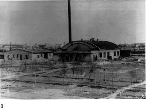
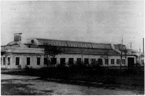
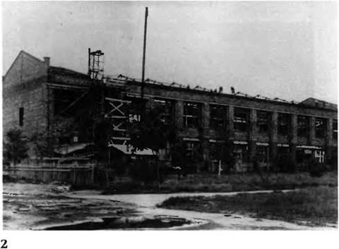
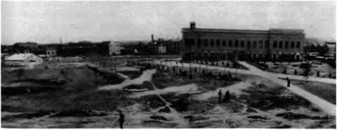
On 16 March 1942, by government decree, the OKB managed by Mikoyan was reorganized within the no. 155 factory area in Moscow. The area was in fact a wasteland near the Leningrad causeway that held a few crumbling huts, several barracks, an antiquated boiler room, and a small one-story building. It was in the latter that the design bureau set up shop on a primitive level in April 1942 after its return from Kuybyshev, to which it had been evacuated the year before. Quite rapidly, critical restoration and construction projects were completed (1) The site after initial repairs in 1942. (2) The first assembly workshop. (3) Construction of the building planned to accommodate the design bureau. (4) The site in 1943.
її
|
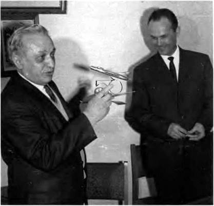
This photograph was taken in March 1969, a few weeks before Mikoyan suffered the stroke that ended his career. He hands R. A. Belyakov a present for his fiftieth birthday: a sculpture symbolizing Belyakov’s two passions, aviation and skiing.
|
So keep calm.” If I had doubts about something, I could always knock at his door. I took part in all important meetings—Mikoyan, who was prone to headaches, abhorred business meetings and frequently sent me in his place, many times at the last minute. Because of my different activities, I was well known in all the departments. As you can see, I was in the best position to take over.
WieZZ then, is aviation the one and only passion in the life of Rostislav Apollosovich?
Of course not. When I was a student I loved skiing, especially Alpine skiing and ski jumping. I was a five-time champion in the USSR, once in ski jumping and four times in downhill racing, and I am quite proud of that. With one of my professors, Zhuravchenko, I even ‘’tested" a man in a wind tunnel to calculate the best descent attitudes. In 1940 I skied down the eastern side of the Elbrus, which reaches some 5,600 meters (18,600 feet) at its highest point. But I should not forget my wife, Ludmilla Nikolayevna. I met her in Kuybyshev, a port on the Volga River where the OKB withdrew in 1941 at the time of the German breakthrough. I returned to Moscow with our engineering office staff in 1942, but my wife-to-be did not return until later. We got married in 1945. She is now retired from her career as a television engineer specializing in large screens. And while I was at MAI I of course learned to fly—either on a Polikarpov Po-2 or a Yakovlev UT-2. I have also made parachute jumps.
You wish to know my shortcomings? I do not know how to relax, how to keep away from my work and think of something else. I like classical music, but I never have time to go to a concert. Besides, I have always regretted not knowing how to play an instrument. I never learned a foreign language either. In my everyday life, I go out for the newspaper and my dog takes me for a walk twice a day. That’s all. There are two great sources of satisfaction in my life: Sergei, my son, who is thirty-nine years old and an engineer at MiG (previously in the automation department, today in the external economic relations department), and Olga Sergeievna, my granddaughter, who is a student at MAI. As you can see, my succession is already assured!
