Category Mig

UTI MiG 9 / FT 2

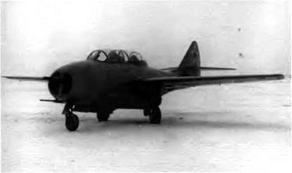
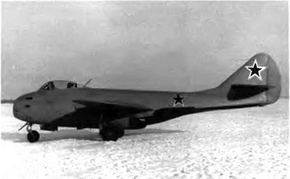
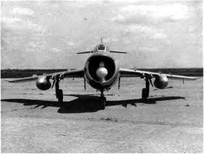
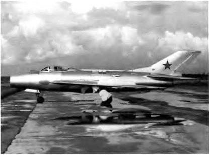
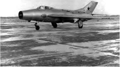
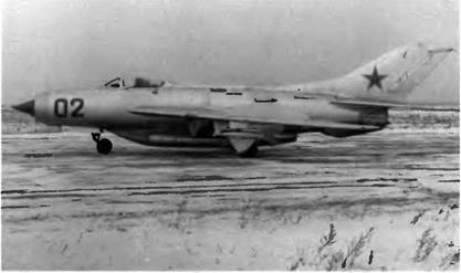
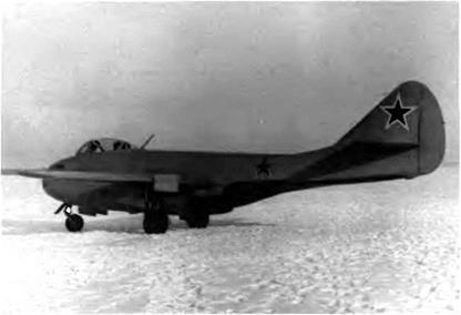
The second UTI MiG-9, rolled out in August 1947, was a version of the FT-1 modified to answer the objections raised in its certification tests. The FT-2 was powered by two 784 daN (800 kg st) RD-20 turbojets. Other modifications included the following:

—visibility was improved for the pilot seated in the rear —airbrakes were set in the wing trailing edge —a FKP S-13 camera gun was positioned in the air intake lip —wing was piped for two underslung tanks

—the bulletproof windshield panel in front was replaced by a larger one with thinner glazing

—the curvature of the lateral glazed panels was modified to improve visibility

—the glazed partition between the student and instructor cockpits was removed

The FT-2 made its first flight on 25 August 1947. During the second test phase the rear cockpit was modified to try out the first Soviet ejec­tion seat.

After completing its factory tests the FT-2 was moved to the Shchelkovo airfield for its state acceptance trials from 4 to 17 Septem­ber 1947 at the Nil WS. The aircraft made forty-seven flights and was airborne for fifteen hours and thirty-two minutes. The chief test pilot was Capt. V. G. Ivanov; he was assisted by A. S. Rozanov, captain-engi­neer. Other GK Nil VVS pilots who took part in these tests included

image90

After an important modification to the canopies, the FT-2 was certified as the UTI MiG-9.

Proshakov, Khomyakov, Antipov, Kuvshinov, Skupchenko, Piku – lyenko, Suprun, Teryentyev, Sedov, Alekseyenko, and Trofimov. The UTI MiG-9 no. 02 (FT-2) received its type certification. The panel also recommended the installation of airbrakes and underwing tanks on all versions of the MiG-9.

Operational MiG-9s flew at 900 km/h (486 kt) without a pilot res­cue system; to remedy that situation—and as part of the WS experi­mental construction program approved by the council of ministers held on 11 March 1947—the MiG ОКБ was instructed to install an ejec­tion seat on the FT-2 and to subject it to official tests. The ejection seat was developed and installed in 1947-48. In one factory test, a man was ejected at nearly 700 km/h (378 kt).

On 29 September 1948 the FT-2 prototype equipped with the ejec­tion seat was handed over to military test pilots. The seat was placed at an angle of 22.5 degrees in the front cockpit and 18.5 degrees in the rear cockpit. It weighed 128.5 kg (238 pounds). During the first two flights, one at 596 km/h (322 kt) and the other at 695 km/h (375 kt), a mannequin was used. During the third flight on 7 October at 517 km/h (279 kt), the fourth flight on 26 October at 612 km/h (330 kt), and the fifth flight on 13 November at 695 km/h (375 kt), Flight Lt. A. V. Bistrov and his substitute, N. Ya. Gladkov, were ejected. The FT-2 was flown by Capt. V. G. Ivanov. Before these tests started, ten ejections had been carried out on the ground whose accelerations ranged from 8 to 15 g.

image91

On the MiG-9M the location of the three guns was completely revamped. Their muz­zles were set back from the air intake plane.

Specifications

Span, 10 m (32 ft 9.7 in); length, 9.83 m (32 ft 3 in); height, 3.225 m (10 ft 6.7 in); wheel track, 1.95 m (6 ft 4.8 in); wheel base, 3.072 m (10 ft 0.9 in); wing area, 18.2 m2 (195.9 sq ft); empty weight, 3,460 kg (7,626 lb); takeoff weight, 4,895 kg (10,788 lb); crew, 180 kg (397 lb); fuel, 862 kg (1,900 lb); gas, 14 kg (31 lb); oil, 22 kg (49 lb); armament, 205 kg (452 lb); ammunition, 116 kg (256 lb); removable equipment, 36 kg (79 lb); wing loading, 269 kg/m2 (55 1 lb/sq ft).

Performance

Max ground speed, 810 km/h (437 kt); climb to 5,000 m (16,400 ft) in 5.3 min; service ceiling, 12,000 m (39,360 ft); landing speed, 180 km/h (97 kt); range, 775 km (480 mi); design range with two 235-1 (62-US gal) drop tanks, 920 km (571 mi); takeoff roll, 835 m (2,740 ft); landing roll, 775 m (2,540 ft).

MiG 15 bis / SD

In 1946 the Klimov ОКБ developed the VK-1, a more powerful version of the RD-45F boosted to 2,645 daN (2,700 kg st). Because this engine was practically the same size and weight as the RD-45F it could be installed in the MiG-15 without many modifications, confirming the hopes pinned on the aircraft’s growth potential. This is how the MiG-15 gave way to the MiG-15 bis.

Its silhouette did not differ much from that of the MiG-15, but it offered better performance. The wing structure was strengthened, the pitch trim was increased to 22 percent, and the shape of the elevator and rudder noses was modified. The upper surface of the wing was fit­ted with a long, squared blade called a nozh (knife) to retard any stall tendency. The airbrakes, whose set switch was on the pilot’s stick, were redesigned. But the most successful innovation was the use of a BU-1 servo-control—with its own hydraulic system—on the aileron con­trol. The hydraulic system for the flaps was backed up by a pneumatic system.

The SD armament comprised one N-37 cannon with 40 rounds, two NS-23KMs with 160 rounds. The gunsight was of the ASP-3N type.

image134

The greater thrust of the VK 1 improved the performance of the MiG-15 bis signifi­cantly.

With four store stations under the wing, the aircraft could cany two 50- kg (110-pound) or 100-kg (220-pound) bombs and two 250-1 (66-US gal­lon) drop tanks. New tactical methods were tested with the MiG-15 bis. For instance, the aircraft was to be able to drop bombs upon invading bombers at altitudes of up to 12,000 m (39,360 feet) and speeds of up to 700 km/h (378 kt). For this unusual assignment the MiG-15 bis carried special 100-kg (220-pound) OFAB-IOOM and PROSAB-100 bombs that were fused at the command of the squadron leader. The cockpit pres­surization system was improved, the pilot had a warming system for his legs, and the windscreen front panel was made of 64-mm-thick bul­letproof glass.

The MiG-15 bis was built in two versions: one that was equipped with an OSP-48 instrument landing system and one that was not and therefore was limited to daytime missions. The first series had an RSI-6 VHF transceiver (later replaced by an RSIU-3), and installation of the first SRO IFF transponders was already planned.

In 1952 a few of these planes were fitted with a 15-m2 (161.5-square foot) brake chute to make it possible for them to use small airfields. It is worth noting that because of the aircraft’s strength, handling, and flutter characteristics, Mikoyan had limited its speed to 1,070 km/h (578 kt) IAS or Mach 0.92. For the first time, pilots wore

image135

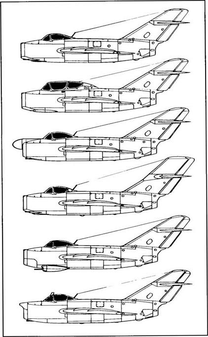
Top to bottom: MiG-15 bis, UTI MiG-15 (ST), MiG-15 bis (SP-1), MiG-15 bis (SYe), MiG – 15 (SU), and MiG-15 bis (SP-5) (MiG ОКБ drawing)


the PPK-1 g-suit aboard the MiG-15 bis It increased the pilot’s resis­tance to the effects of gravitational accelerations experienced at high altitudes and worked best at between 1.75 and 8 g

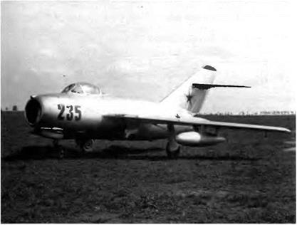
Also in 1952 a TS-23 periscope was installed on MiG-15 bis no. 235 to help the pilot look backward in combat or while taxiing. It was devel­oped by the Vavilov State Optical Institute, a branch of the defense ministry. The optical head of the periscope was located on the canopy’s windshield arch, and its mirror was hung on it. A heating coil kept the glass clear. The field of view scanned by the TS-23 was 16 degrees. But it was not certified, and its development was halted From 1 June 1952 a new model, the TS-25, was tested, it was a one-piece periscope placed on the canopy and offering a much wider field of view. The TS-25 allowed pilots to watch the sky behind them and spot aircraft approach­ing from that sector without having to focus solely on the periscope It covered between 50 and 55 degrees on each side of the aircraft’s longi­tudinal axis and between 20 and 25 degrees vertically This periscope was approved for use in Soviet aircraft. The MiG-15 bis—as well as the MiG-17 and all its variants—was equipped with either the TS-25 or the improved TS-27

The MiG-15 bis was built under license m Czechoslovakia (620 units referred to as S 103s) and in Poland (LIM-2s).

The following details refer to the MiG-15 bis equipped with an OSP-48 instrument landing system weighing 84 kg (185 pounds)

Specifications

Span, 10 085 m (33 ft 1 in); overall length, 10.102 m (33 ft 1.7 in); fuse­lage length. 8.125 m (26 ft 7.9 in); wheel track, 3 852 m (12 ft 7 6 in), wheel base, 3 23 m (10 ft 7 2 in); wing area, 20.6 m2 (221.7 sq ft), empty weight, 3,681 kg (8,113 lb); takeoff weight, 5,044 kg (11,117 lb), max takeoff weight clean, 5,380 kg (11,857 lb); with two 260-1 (69-US gal) drop tanks, 5,508 kg (12,140 lb); with two 300-1 (79-US gal) drop tanks, 5,574 kg (12,285 lb); with two 600-1 (158-US gal) drop tanks, 6,106 kg (13,458 lb); fuel, 1,173 kg (2,585 lb); wing loading, 244 9-296.4 kg/m2 (50.2-60.8 lb/sq ft).

Performance

Max speed, 1,107 km/h at 3,000 m (598 kt at 9,840 ft); 1,014 km/h at 5,000 m (548 kt at 16,400 ft); max speed at sea level, 1,076 km/h (591 kt); climb to 5,000 m (16,400 ft) in 1 95 min; to 10,000 m (32,800 ft) in 4.9 min; service ceiling, 15,500 m (50,840 ft); landing speed, 178 km/h (96 kt); range, 1,130 km at 12,000 m (702 mi at 39,360 ft); with two 260-1 (69-US gal) drop tanks, 1,860 km (1,155 mi), with two 300-1 (79-US gal) drop tanks, 1,975 km (1,227 mi); with two 600-1 (158-US gal) drop tanks, 2,520 km (1,565 mi), endurance at 12,000 m (39,360 ft), 2 h 6 min; with two 260-1 (69-US gal) drop tanks, 2 h 57 min; with two 300-1 (79-US gal) drop tanks, 3 h 9 min; with two 600-1 (158-US gal) drop tanks, 3 h 52 min; takeoff roll, 475 m (1,560 ft); landing roll, 670 m (2,200 ft).

MiG 17R / SH-2 SR 2s/MiG-17F

The SR-2, derived from a MiG-17F airframe, was designed to study the feasibility of a frontline photo-reconnaissance aircraft powered by the new VK-5F turbojet. The preliminary designs of the SR-2 and VK-5F were ordered by decree no. 2817-1338 signed on 3 August 1951 by the USSR council of ministers. Strangely, the aircraft’s performance data were not described in the council’s specifications. The structure of the cannon tray was now riveted; new equipment included a MAG-9 tape recorder and a special AFA-BA-21s camera capable of taking oblique, vertical, or double-corridor-wide photos. A hydraulic servo-control was added to the elevator control, and the instrument panel was rearranged once more.

The VK-5F was rated at 2,940 daN (3,000 kg st) maximum dry thrust and 3,775 daN (3,850 kg st) with reheat. Its afterburner was much more efficient than that of the VK-1F thanks to an increase in turbine inlet temperature, the use (for the first time) of refractory alloys resistant to thermal stress for turbine blades, and better cooling. Because of this new technology the reheated thrust was 460 daN (470 kg st) greater than that of the VK-1F—but the size, weight, and specific fuel consumption of the two engines were identical. The VK-5F was certainly an unqualified success for the Klimov OKB.

To counterbalance the weight of the SR-2 camera set, the N-37D cannon was removed. The two NR-23s with 100 rpg were retained. The pilot could use the tape recorder to note all of his observations while flying a mission, saving him the bother of taking notes on his plotting chart or remembering a lot of details until debriefing time. The camera was attached to a tilting tray that permitted to take either single – or double-corridor vertical or oblique photos with a 30-degree setting angle in relation to the horizontal (on the left side of the flight path). Small protective flaps that opened automatically before each shot were flushed into the skin of the fuselage just in front of the camera lens. While the aircraft was on the ground these flaps remained closed, pro­tecting the lens against foreign objects The AFA-BA-21s camera could be replaced by the more sophisticated AFA-BA-40R. The SR-2 was equipped with a curtain-type ejection seat fitted with stabilizing panels.

The aircraft was rolled out in May 1952 and made its first flight under A. N. Chemoburov in June. Factory tests continued for quite a long time—until January 1954 The state acceptance trials were con­ducted concurrently, lasting from July 1952 until 10 August 1954. They were earned out by two military pilots, S. A. Mikoyan and P. N Belyas – mk both wing commanders. The state test report concluded: "1. The SR-2, powered by a VK-5F turbojet has passed its state acceptance tri­als. 2. Entry into service of a VK-5F-powered MiG-17R has no justifica­tion, since its performance is not very different from that of the VK-1F – powered MiG-17F. 3. On the other hand, we recommend the produc­tion of the MiG-17R powered by the VK-1F and with the same camera installation." Thus, while the SR-2 met the state’s specifications, it was not recommended for air force units But the SR-2s—which carried the same photographic equipment as the SR-2 but was powered by a VK-1F engine—was accepted after a series of tests as the air force’s frontline daytime photo-reconnaissance aircraft and, surprisingly, named the MiG-17F. In this case the "F" stood for fotografia (photography) and not forsirovanie (reheat), as is commonly presumed.

The following details refer to the SR-2.

image171

The MiG-17PFU was equipped with the RP 1 Izumrud radar and could carry two slip­per tanks with a capacity of 400 1 (106 US gallons) apiece

Specifications

Span, 9.628 m (31 ft 7 in), length, 11 36 m (37 ft 3.2 in); height, 3 8 m (12 ft 5.6 in), wheel track, 3.849 m (12 ft 7 5 in), wheel base, 3 368 m (11 ft 0.6 in), wing area, 22.6 m2 (243.3 sq ft); takeoff weight, 5,350 kg (11,790 lb), wing loading, 236.72 kg/m2 (48.5 lb/sq ft)

Performance

Max speed, 1,132 km/h (611 kt); service ceiling, 16,800 m (55,100 ft); range with two 600-1 (158-US gal) drop tanks, 2,115 km (1,313 mi), climb to 5,000 m (16,400 ft) in 2 min

SM-12PM

This experimental interceptor, powered by two R3-26 turbojets, was also built in 1957. Like the SM-12/3, the air intake on the SM-12PM had a two-position nose dome, but this one was much more bulky because it had to house the TsD-30 radar antenna.

Instead of cannons the SM-12PM carried two RS-2U air-to-air mis­siles on wing pods. Its maximum speed reached 1,720 km/h (929 kt), and its service ceiling was 17,400 m (57,000 feet). It could climb to

10,0 m (32,800 feet) in four minutes. Its maximum range without drop tanks was 1,700 km (1,055 miles).

image211

The SM-12/1 and SM-12/2, built at the same time as the SM-12/3, differed only in their equipment. The reshaping of the engine air intake foreshadowed already that of the MiG-21.


image212

image213

The SM-12PM had a much larger nose cone than the MiG-19. The two air-to-air mis­siles are of the RS-2U type.

image214

The SM-12PMU had a new power plant, including a rocket engine, and was armed with two RS-2US (K-5M) air-to-air missiles.

?tn

Ye-152/1 / Ye 152/2

The Ye-152 represented the synthesis of two experimental prototypes: the Ye-150, test bed of the R-15-300 turbojet, and the Ye-152A, used to test the Uragan-5 automatic interception system and Mikoyan K-9 air – to-air missiles The Ye-152 was actually rolled out after the Ye-152A. On the recommendation of two test pilots, G. K. Mosolov and A. V.

This photograph shows the Ye-152/1 with a drop tank under the fuselage and, at the wing tips, models of the K-9 air-to-air missile under development

Fedotov, the new aircraft had a lower wing loading and better yaw sta­bility; the wing tip shakes and the aileron flutter were eliminated, and its taxiing conditions were improved. The new wing was larger thanks to a deeper tip chord, a modification that allowed missiles to be installed there. Its enhanced handling in ground maneuvers was due to a wider wheel track made possible by the modification of the wing structure. The yaw stability was rectified by increasing both the fin chord and area of the ventral fin so that the tail section could play a more efficient part in the tail fin’s work. The Ye-152 was designed to intercept and destroy on collision course any invader at 1,600 km/h at

10,0 m (864 kt at 32,800 feet) or 2,500 km/h at 20,000 m (1,350 kt at 65,600 feet) and beyond.

The diamond wing had a sweepback of 53 degrees, 47 minutes at the leading edge and a thin airfoil section (the thickness-chord ratio was 3.5 percent at the wing root and 5 percent at the wing tip). The triple-angle cone was fixed and made of dielectric material to house the radar antenna, like the Ye-150. Moreover, the Ye-152 had the same translating annular cowl as the Ye-152A. The cone’s annular base plate was perforated to bleed the boundary layer in order to increase the total pressure recovery factor at the compressor inlet level. The sole airbrake was located under the fuselage, and the container for the PT – 5605-58 tail chute was placed at the base of the ventral fin.

All flying controls were boosted by hydraulic servo-controls—two BU-65s for the slab tailplane, one BU-120M per aileron, and one BU – 120M for the rudder. The hydraulic system used AMG-10 fluid and could handle pressures of 210 atmospheres. The autopilot was the AP – 39. The total capacity of the fuel tanks in the fuselage and wing was 4,960 1 (1,310 US gallons), and a PB-1500 drop tank attached under the fuselage could carry another 1,500 1 (396 US gallons). In the event of ejection the pilot was protected by the cockpit hood. The R-15-300 tur­bojet of the Ye-152 was slightly more powerful than that of the Ye-150: 6,750 daN (6,800 kg st) of dry thrust and 10,005 daN (10,210 kg st) with afterburner. The Ye-152, like the Ye-150, was equipped with an ejector.

The first prototype or Ye-152/1 was moved to the test center on 16 March 1961. For the first flight by G. K. Mosolov on 21 April, provisional ballast of 263 kg (580 pounds) was placed in the nose. Tests continued until 8 January 1962, started up once more on 2 March, and were fin­ished by 11 September; sixty-seven flights were made—fifty-one with launching rails, five with missiles, and eleven in clean configuration.

The second prototype or Ye-152/2 took advantage of all the adjust­ments made during the Ye 152/1 tests and was significantly modified in two ways (1) to expand the pitch stability margin, the fuel tanks’ uti­lization sequence was altered – and (2) the boundary layer bleed device was improved by increasing the area of the perforated cone base plate. The flight envelope of the Ye-152/2 was tested up to a speed of 2,740 km/h (1,480 kt) at 22,500 m (73,800 feet) under clean conditions, and as far as Mach 2.28 at 18,000 m (59,000 feet) with K-9 missiles attached to the wing tips Flying the Ye-152/2 proved to be very similar to flying the Ye-152/1 But cancellation of the Ye-152/1 tests as well as those of the K-9 missile sealed the fate of the Ye-152/2. Only 60 percent of its test schedule was completed.

Specifications

Span, 8.793 m (28 ft 10.2 in); overall length (except probe), 19.656 m (64 ft 5.9 in); fuselage length (except cone), 16.603 m (54 ft 5.7 in); wheel track, 4.2 m (13 ft 9,4 in); wheel base, 6.265 m (20 ft 6.7 in), wing area, 42.02 m2 (452.3 sq ft); empty weight, 10,900 kg (24,025 lb); takeoff weight, 14,350 kg (31,630 lb); max takeoff weight, 14,900 kg (32,840 lb), fuel, 4,150 kg (9,145 lb), wing loading, 341 5-356.6 kg/m2 (70-73.1 lb/sq ft).

Performance

Max speed, 2,510 km/h at 10,000 m (1,355 kt at 32,800 ft); 3,030 km/h at 15,400 m (1,636 kt at 50,500 ft); climb to 10,000 m (32,800 ft) in 3 67 min; to 20,000 m (65,600 ft) in 5.33 min; service ceiling, 22,670 m (74,360 ft); landing speed, 260-270 km/h (140-146 kt); range with one

271

At the wing tips of this Ye-152P are models of the new R-4 air-to-air missile under development.

1,500-1 (396-US gal) drop tank, 1,470 km (915 mi); takeoff roll with two K-9s, 1,185 m (3,885 ft); landing roll, 1,270-1,300 m (4,165-4,265 ft).

MiG 21PFM / MiG-21PFS / Ye-7SPS / Tip 34

The MiG-21 silhouette was again retouched. The tail fin chord was increased to improve the yaw stability margin total area rose to 5.35 m2 (57.26 square feet) without increasing the size of the rudder. The tail chute container found itself back—for good—at the base of the tail fin, and the chute canopy was given a cruciform shape. But the most significant modification was the addition of the SPS system (Sduv Pogranichnogo Sloya. boundary layer blowing) Air bled from the turbo­jet HP compressor was blown over the flaps’ upper surface, accelerat­ing the boundary layer speed and thereby delaying its separation. The overall wing lift was thus increased when the aircraft landed (pilots used SPS by choice). The MiG-21s equipped with this system were eas­ily recognizable by their bulky flap-actuator fairings located at flap midspan. The area of the flaps was slightly reduced to 0.92 m2 (9.9 square feet) per unit from the 0.935 m2 (10.06 square feet) of previous versions. Their deflection was 25 degrees at takeoff and a maximum of 45 degrees at landing. The engine was the same as that of the MiG – 21 PF, but the letter s (for Sduv) was added to its official name. It thus became the R-11F2S-300 (or 37F2S in some documents). It was rated at 6,050 daN (6,175 kg st) with afterburner

The cockpit canopy was thoroughly modified. Instead of opening upward with hinges to the front, it was divided in two elements: a fixed windshield and a canopy hinged to starboard. This change was linked to the installation of the new KM-1 third-generation ejection seat (the canopy was no longer needed to protect the pilot during the initial ejec­tion sequence). The KM-1 was not yet a true zero-zero ejection seat because its operating range was, with the exception of altitude (0-25,000 m [0-82,000 feet]), limited by speed (130-1,200 km/h [70-648 kt]). This cockpit rearrangement led to a slight reduction of the fuel tanks’ capacity: 2,650 1 (700 US gallons) versus 2,750 1 (726 US gallons) in the PF.

So that it could be used from unprepared strips, the MiG-21PFM could be fitted with two SPRD-99 solid rocket boosters each rated at 2,450 daN (2,500 kg st). The aircraft thus possessed a complete package

of systems to improve takeoff performance (afterburner, boosters) as well as landing performance (flaps, SPS, airbrakes, PT-21UK tail chute, wheel brakes).

Armament included two air-to-air RS-2US (K-5M) semiactive radar homing missiles (leading to the installation of the RP-21M radar and a modification of the aircraft’s wiring diagram) as well as Kh-66 air-to-sur – face missiles. This weaponry could be supplemented by the GP-9 gun pod (a twin-barrel 23-mm GSh-23 cannon) under the center part of the fuselage and the ASP-PF-21 gunsight in the cockpit. The radar warning receiver was a Sirena-3M, and the new IFF interrogator had the rather curious appellation of Khrom-Nikyel ("chromium-nickel”) Before the MiG-21 PFM was ready, a small batch of MiG-21 PFSs were allotted to a fighter regiment This version differed from the PFM only in its engine which featured an additional mode of throttleable afterburning to improve significantly the aircraft’s acceleration time.

The MiG-21 PFM was mass-produced in the Gorki factory between 1964 and 1965 for the WS and in the MMZ Znamya Truda factory in Moscow between 1966 and 1968 for export.

Specifications

Span, 7.154 m (23 ft 5.7 in); fuselage length (except cone), 12 285 m (40 ft 3.7 in) height, 4.125 m (13 ft 6 4 in); wheel track, 2 787 m (9 ft 1.7 in); wheel base, 4.71 m (15 ft 5 4 in); wing area, 23 m2 (247 6 sq ft), takeoff weight, 7,820 kg (17,235 lb); max takeoff weight, 9,080 kg (20,010 lb); max takeoff weight on rough strip or metal-plank strip, 8,800 kg (19,395 lb); fuel, 2,200 kg (4,850 lb); wing loading, 340-394.8 kg/m2 (69.7-80.9 lb/sq ft); max operating limit load factor, 8.5.

Performance

Max speed, 2,230 km/h at 13,000 m (1,204 kt at 42,640 ft); max speed at sea level, 1,300 km/h (702 kt), climb rate at sea level (half internal fuel, full thrust) with two R-3S missiles, 125 m/sec (24,600 ft/ mm); climb to 18,500 m (60,680 ft) in 8 min; service ceiling, 19,000 m (62,320 ft); landing speed, 250 km/h (135 kt); range, 1,300 km (810 mi); with 800-1 (211-US gal) drop tank, 1,670 km (1,035 mi); takeoff roll, 850 m (2,790 ft); landing roll with SPS and tail chute, 550 m (1,800 ft).

MiG 23 / 23-11/1

While one ОКБ team was at work on the 23-01, another tried to show that the variable geometry wing concept was well founded. Both proj­ects were aimed at one objective: aircraft capable of speeds of Mach 2-2.3 and STOL performance. The 23-11 fuselage was shaped like a pointed cigar developing into a rounded-off angled square between frame nos. 18 and 20. The structure located in the midst of these two bulkheads was essential: it was the wing’s center section, plus a fuel tank into which the air intake duct passed. The attachment fittings for the actuating cylinders of the main gear as well as the front ends of the gimbal joints were secured to its rear face (frame no. 20). The body then tapered to frame no. 28, where the whole rear fuselage could be detached to ease field maintenance and engine removal.

Bulkhead no. 31 at the rear of the fuselage supported the hinges for the four airbrakes, the support bearing for the stabilator, and the rear attachment fitting for the vertical fin. The skin was fabricated out of panels connected by fusion welds and then riveted. The wing box was made of the two main spars. The minimum sweep angle at the leading edge was 16 degrees, increasing steadily to a maximum of 72 degrees. Wing sweep was controlled by an SPK-1 hydraulic system whose two ball-screw actuators transformed spin to linear motion. Those actuators were linked directly to each wing’s pivot arm. Pins were located on the center section 1,500 mm (59.06 inches) on either side of the fuselage datum line and lengthwise 128.5 mm (5.05 inches) ahead of bulkhead no. 20.

The wing’s sweep angle could be modified by a control lever on the left console of the cockpit, and the pilot could follow the movement via the wing position indicator on the instrument panel. Each wing had leading edge (LE) flaps; single-slotted trailing edge (ТЕ) flaps, in four sections; and two-section upper surface spoilers/lift dumpers forward of midflap sections. Extension of the LE and ТЕ flaps was linked, but the LE controls featured a nonlinear mechanism that kept the angles from being identical. If the ТЕ flaps were at 25 degrees at takeoff, the LE flaps were at 17 degrees; and when the ТЕ flaps were at 50 degrees at landing, the LE flaps were at 19 degrees (their maximum). LE and

In this photograph the 23 11/1 has its wing set at the maximum sweep angle of 72 degrees.

ТЕ flaps remained linked only if the wing was set at 16 degrees. Above that, the linkage rods automatically disengaged.

On the wing’s upper surface, each spoiler was hinged on the rear mam spar and acted like an aileron when operating differentially in conjunction with the horizontal tail surfaces. With a 16-degree wing sweep angle, its maximum deflection travel was 45 degrees. With a 72- degree wing sweep angle, the spoilers locked in the retracted mode and roll control was provided only by the horizontal tail surfaces operating differentially (tailerons). Between 16 and 72 degrees, the spoiler angle changed according to the sweep angle chosen by the pilot. Rudder con­trol was provided by an irreversible servo-control unit supplemented by spring mechanisms to transmit the "feel." Operating spoilers instead of ailerons avoided the risk of wing twist when displacing ailerons at high speeds.

The 23-11 prototype was powered by the Khachaturov R-27F-300 (product 41) rated at 5,095 daN (5,200 kg st) dry or 7,645 daN (7,800 kg st) with afterburner The nozzle area could be adjusted by means of a double ring of small flaps. Engine power was regulated at all ratings by a single linear throttle (the first of its kind at MiG), the variable geome­try air intakes, and the blow-in doors (two for each intake duct). The specific fuel consumption of the 23-11/1 in level flight was 25 percent less than that of the MiG-2 IS with the much less powerful R-l 1F2-300

The UVD-23 control system of the boundary layer splitter plates offered full thrust at any and all times and ensured that the engine functioned reliably at all ratings in the aircraft’s flight envelope. The leading edges of the splitter plates at the air intakes stood 55 millime­ters (2.16 inches) away from the fuselage wall, forming a boundary layer bleed duct. The UVD-23 apparatus was useful for setting the split­ter plates to the most suitable position as the engine compressor pres­sure ratios ranged between 4 and 11. Automatic control took over when the aircraft reached Mach 1.15 and was governed by the deflec­tion of the stabilator.

In the 23-11/1, 4,250 1 (1,122 US gallons) of fuel were distributed among three fuselage integral tanks of 1,920, 820, and 710 1 (507, 217, and 188 US gallons) and six wing structural tanks: two each of 62.5, 137.5, and 200 1 (16.5, 36.3, and 52.8 US gallons). The first production machines also carried a drop tank under the fuselage Because wing sweep varied, the fuselage-to-wing fuel and air lines passed through telescopic swivel joints.

The lower segment of the large ventral fin was hinged to fold to starboard when the landing gear was extended. The three gear legs were fitted with levered suspension. The main gear featured KT-133 trailed wheels with 830 x 225 tires (later increased to 830 x 300). The front leg had twin wheels with 520 x 125 tires and was fitted with the MRK-30 nosewheel steering mechanism, a shimmy damper, and a wheel centering device. All wheels were equipped with hydraulically controlled disc brakes. As the aircraft was being planned, conceiving the gear was like trying to square the circle. Because of the variable geometry concept the gear had to be housed entirely into the fuselage, but at the same time the wheel track had to remain fairly broad. This explains the seeming complexity of its kinematics.

The PT-10370-65 tail chute with an area of 21 m2 (226 square feet) was housed in a cylinder at the base of the rudder with split cone – shaped doors. Armament of the 23-11/1 included four air-to-air K-23 missiles (two under the wing glove and two under the fuselage); during the tests K-13 missiles were also fired.

The 23-11/1 was moved to the test center on 26 May 1967, and after the usual ground and runway exercises the aircraft made its first flight on 10 June 1967 under the guidance of OKB chief pilot A. V. Fedotov. The first thirteen flights were devoted to preparing for the Domodyedovo air show. During that event on 9 July Fedotov gave a brilliant demonstration of all the capabilities of the VG concept. Subse­quent flights explored the flight envelope and assessed the efficiency of the air intakes.

On 9 July 1967 at the Domodyedovo air show, Fedotov put on a remarkable demon­stration of the 23-11 variable geometry aircraft. It was the prototype’s fourteenth flight.

The R-27F-300 reached its twenty-five hour life limit on the proto­type’s forty-fifth flight. Tests resumed in January 1968 after the engine was replaced and the aircraft was equipped with the three-axis AP-155 autopilot. In early April the 23-11 moved to an airfield not far from a firing range to examine the operation of the air intakes and turbojets as well as the aircraft’s handling characteristics when firing K-13 and K-23 missiles. Those tests took place between 8 April and 24 April. P. M. Ostapyenko and M. M. Komarov fired sixteen unguided missiles (the aircraft did not yet have radar). No surges or flameouts occurred between 5,000 m (16,400 feet) and 17,000 m (55,760 feet) and speeds of

Mach 0.7 to Mach 1.8 during the firing tests. The basic test schedule ended in July after ninety-seven flights. The factory report concluded:

The MiG-23 variable geometry wing offers many advantages, such as

— a significant reduction of the takeoff and landing rolls (compared with those of all other existing aircraft in the same category)

— a great ease of handling in the entire flight envelope and especially at takeoff and landing

— a high indicated airspeed (IAS) at low altitude and, at max­imum sweep, low g-forces in rough air

— a long range and a high flight endurance at cruise rating

Design performance should be met with the more powerful R-27F2-300 turbojet (product 47) that the aircraft needs.

On 6 November 1968 A. I. Mikoyan confirmed the 23-11/1 factory test report. This prototype, with its original markings, can be seen today in the VVS museum on the Monino airfield near Moscow.

Specifications

Span (72′ sweep), 7.779 m (25 ft 6.3 in); span (16° sweep), 13.965 m (45 ft 9.8 in); fuselage length (except probe), 15.795 m (51 ft 9.8 in); wheel track, 2.658 m (8 ft 8.7 in); wheel base, 5.772 m (18 ft 11.3 in); wing area (72° sweep), 29.89 m2 (321.74 sq ft); wing area (16° sweep), 32.1 m2 (345.52 sq ft); takeoff weight in clean configuration, 12,860 kg (28,345 lb); takeoff weight with four K-23 missiles, 13,300 kg (29,315 lb); wing loading (72° sweep), 424.2-445 kg/m2 (86.9-91.2 lb/sq ft); wing loading (16° sweep), 400.6-414.3 kg/m2 (82.1-84.9 lb/sq ft); max operating limit load factor, 3.1.

Performance

Max speed in clean configuration (72° sweep), 2,240 km/h or Mach 2.12 at 13,600 m (1,208 kt at 44,610 ft); max speed with two K-23 mis­siles (72° sweep), 2,255 km/h or Mach 2.13 at 13,400 m (1,217 kt at 43,950 ft); max speed with four K-23 missiles (72° sweep), 2,025 km/h or Mach 1.905 at 12,800 m (1,214 kt at 41,985 ft); service ceiling, 17,200 m (56,415 ft); landing speed, 230 km/h (124 kt); takeoff speed, 270 km/h (146 kt); feriy range with two underbelly K-23 missiles (16° sweep), 2,045 km (1,270 mi); takeoff roll, 320 m (1,050 ft); landing roll with tail chute, 440 m (1,445 ft); landing roll without tail chute, 750 m (2,460 ft).

MiG 25PU / 39 / Ye 133 MiG 25RU / 22

This MiG-25PU was in fact the Ye-133, which set several world records between 1975 and 1978.

tors, automatic flight control system, power plant and aircraft controls, fluid cooling units, air-conditioning ducts, and the like) were updated and modified to make possible all kinds of simulated failures. After improvements to the ejection devices, the instructor could himself eject the student pilot in an emergency. The performance data of the MiG-25PU and RU did not diverge greatly from those of the basic ver­sions except for the never-exceed Mach number (Mne), lowered from 2.83 to 2.65 as a safety measure.

Ye-133 Records

Several female world records were beaten by a MiG-25PU renamed Ye-133 for this purpose and piloted by Svetlana Ye. Savitskaya.

1. 22 June 1975. Speed over a 15- to 25-km (9- to 15-mile) course at unrestricted altitude, 2,683.446 km/h f1,546.26 kt)

2. 31 August 1977. Altitude in horizontal flight, 21,909.9 m (71,864 47 feet)

3. 21 October 1977. Speed over a closed circuit of 500 km (310 miles), 2,466.31 km/h (1,331 81 kt)

4. 12 April 1978. Speed over a closed circuit of 1,000 km (621 miles), 2,333 km/h (1,259.8 kt)

SVB, a Mountaineer

This commuter was engineered to carry fifty passengers or cargo in hot mountainous regions. It can be operated in hot climates up to 40 ° C (104° F) and out of high-altitude airfields up to 4,000 m (13,120 feet) above sea level. The SVB is powered by two TV7-117 turboprops rated at 1,840 kW (2,500 ch-e); they drive low-noise SV-34 six-blade airscrews. The cabin, which maintains a constant width from the cock­pit rear bulkhead, is pressurized and dimensioned to accommodate ten rows of five seats—separated into three and two by the aisle, 400 mm (15.75 inches) wide—at a pitch of 780 mm (30.71 inches). The cabin is 2.96 m (9 feet, 8.5 inches) wide, with headroom of 2 m (6 feet, 6.7 inch­es). The aircraft has a flight crew of two plus two cargo handlers or cabin attendants, as appropriate.

In its all-freight setup the SVB can carry a payload of 5,000 kg (11,000 pounds). At the rear of the fuselage is a loading ramp for vari­ous types of vehicles. An integral ceiling hoist helps to manipulate the freight inside the cargo hold. The aircraft is equipped with a digital

SVB (MiC OKB three-view drawing)

For fifty passengers. Seats pitched at 750 mm.

For 5,000 kg (11,000 pounds) of cargo.

Possible arrangements of the SVB’s interior.

flight management system and integrated communications capabili­ties, allowing all-weather and around-the-clock operations.

Specifications

Span, 25.9 m (84 ft 11.7 in); length, 22.2 m (72 ft 10 in); height, 8.07 m (26 ft 5.7 in); wing area, 62 m2 (667.37 sq ft); takeoff weight, 19,400 kg (42,760 lb); payload, 5,000 kg (11,000 lb); fuel, 2,100 kg (4,630 lb); wing loading, 312.9 kg/m2 (64.15 lb/sq ft).

Design Performance

Cruising speed, 550 km/h at 6,000 m (297 kt at 19,680 ft); range, 1,500 km (930 mi) with 5,000-kg (11,000-lb) payload and 45 min of fuel reserves; required field length, 1,800 m (5,900 ft) on rough strip capa­ble of 5-6 kg/cm2 (71.1-85.3 lb/sq in) at 2,100 m (6,890 ft) and 30° C (86° F); max field altitude, 4,000 m (13,120 ft); energetic efficiency, 23.6 g/pax-km.

MiG 9M /1308 / FR

The engine flameout that occurred when all three cannons were fired at once puzzled OKB engineers and led them to examine the stability of the combustion process at that moment. This mystery was solved by degrees. It was thought that the solution lay in shifting the cannon

image92

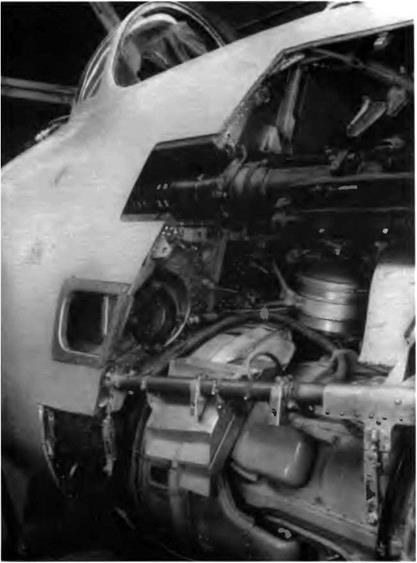
The MiG-9M’s left armament bay. The lower NS-23 has been removed. The N-37 can­non was on the right side of the aircraft’s nose.

muzzles behind the engine air intake plane On the FR, all three can­nons were moved aft: the N-37 was relocated to the right side of the fuselage, and both of the NS-23s were placed on the left side. This new arrangement entailed a few structural modifications of the nose sec­tion. The two RD-20s were replaced by RD-21s built at an OKB man-

image93

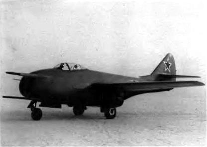
The MiG-9M and the first production MiG-9s were fitted with the airbrakes tested on the UTI MiG-9.

aged by D. V. Kolosov. This was basically a "hotted-up" RD-20 rated at 980 daN (1,000 kg st).

The FR was also equipped with airbrakes first tested on a UTI MiG – 9 as well as a pressurized cockpit. Five of the six original fuel tanks were retained—including a 100-1 (26-US gallon) trim tank—but the total capacity remained unchanged at 1,300 kg (2,865 pounds).

The first FR was rolled out in June 1947 and flown in July by V N. Yuganov. The data recorded during the flight tests showed that it was the first MiG to exceed M 0 8. Thanks to the greater thrust of the RD – 21, the level-speed increase reached 55 km/h (30 kt). The rate of climb also improved: the MiG-9M climbed to 5,000 m (16,400 feet) in 2 min­utes 42 seconds, 1 minute 36 seconds faster than any other aircraft in the same category.

The MiG-9M served as a basic model for the design of both the FL and the FN, two more powerful and sturdier versions that were built but never flown.

Specifications

Span, 10 m (32 ft 9.7 in); length, 9.83 m (32 ft 3 in); height, 3.225 m (10 ft 6.7 in); wheel track, 1 95 m (6 ft 4 8 in); wheel base, 3.072 m (10 ft 0.9 in); wing area, 18.2 m2 (195.9 sq ft); empty weight, 3,356 kg

image94

The FP marked another attempt to end the engine flameout problems that occurred when the cannons were fired simultaneously. The N-37 cannon was moved from the air intake partition wall to the left upper part of the nose.

(7,397 lb); takeoff weight, 5,069 kg (11,172 lb); fuel, 1,300 kg (2,865 lb); wing loading, 278.5 kg/m2 (57.1 lb/sq ft); max operating limit load fac­tor, 5.5.

Performance

Max speed, 965 km/h at 5,000 m (521 kt at 16,400 ft); max speed at sea level, 850 km/h (459 kt); climb to 5,000 m (16,400 ft) in 2.7 min; ser­vice ceiling, 13,000 m (42,640 ft); landing speed, 166 km/h (90 kt); range, 830 km (515 mi); takeoff roll, 830 m (2,720 ft); landing roll, 700 m (2,295 ft).