Category Mig

MiG-15 Series

MiG-15 /1-310 / S |S-D1 andS-D2|

By 1947 every avenue that promised to increase the thrust of the RD – 10 turbojets had been explored. The TR-1 was not fully developed and therefore could not power a fighter prototype. A liquid-propellant rock­et engine (ZhRD) like that of the 1-270 (Zh) could not be used in a com­bat aircraft because of its short operating time Thus there was an urgent need for a powerful and reliable turbojet

A year earlier sixty Rolls-Royce turbojets were ordered from Great Britain. Half were Derwent Vs (1,158 daN/1,590 kg st), while the others were Nene Is (2,185 daN/2,230 kg st) and Nene IIs (2,225 daN/2,270 kg st). For their relatively lightweight fighters the Yakovlev and Lavochkin OKBs chose the Derwent V, a lighter engine (565 kg [1,245 pounds]) that would later be built in the Soviet Union as the RD-500 But for his projects A. I Mikoyan selected the Nene I, a more powerful but also at 720 kg (1,587 pounds) a much heavier engine. It too was later produced in the Soviet Union, where it was referred to as the RD-45.

A. G. Brunov, deputy general designer, and A. A Andreyev, chief engineer, were entrusted with the management of the program. Sever­al TsAGI experts also took part in the preliminary research effort: S A. Khristianovich, G. P. Svitshchev, V. V. Struminskiy, and P M. Krassil – shchikov. Several types of wing shapes—swept wing, straight wing, and even forward-swept wing—were tested in the TsAGI wind tunnels. At that time the swept wing was not favored for fast aircraft, as is shown by German and English jets designed between 1943 and 1946.

As early as March 1947 wind-tunnel tests indicated that a swept wing with fences was probably the right answer. The TsAGI engineers quickly discovered how to control the transverse stability and master the airflow breakdown. The optimum sweep angle for the wing of the

image111

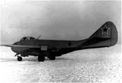
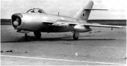
The MiG-15 at its debut was an Anglo-Soviet hybrid This photograph shows the S-01 when it was still only the 1-310.


image112

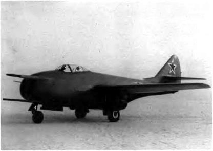
The S-OTs sliding canopy featured a thin arch in the middle


future fighter was calculated to be 35 degrees at 25 percent chord with a 2-degree anhedral from the wing roots The four upper-surface wing fences solved the problem of airflow straightening. But despite its obvi­ous simplicity, the final design of the S-01 was rather unorthodox

From the start, pilot comfort was made a high priority The cockpit was pressurized and air-conditioned, with a canopy that offered an excellent all-around view The aircraft was fitted with an ejection seat. The mechanical flying controls were statically and aerodynamically balanced at a time when hydraulic servo-controls did not yet exist A high degree of serviceability was also considered important Its struc­ture and systems subjected to thorough research, the S aircraft was the result of a mamage of the rational and the useful It was not by chance that the general layout of the 1-310 (S)—the future MiG-15—was recog­nized as a classic and used for several Soviet aircraft (and even by other nations) during the 1950s Its preliminary design allowed for future updates linked to the development of new power plants armament, and equipment.

The 1-310—founder of a great family of experimental and produc­tion machines—proved to be one of the best combat aircraft of the sec­ond postwar generation Its top-notch performance is attributable to its optimum basic wmg load high thrust-to-weight ratio, easy-to-service armament, advanced structural technology, sturdy levered-suspension mam landing gear, and reliable engine

The mam features of this all-metal aircraft included a 35-degree swept wing with four fences a pressurized and air-conditioned cockpit, an ejection seat (the canopy was jettisoned first), and a two-section fuselage The armament included three cannons one N-37D and two NS-23s arranged at first like those of the 1-305 (FL) with all three muz­zles on the same horizontal plane near the engine air intake For the first time on a Soviet fighter, fire warning and extinguishing systems were standard Also for the first time on a fighter, the aircraft was fitted with an OSP-48 instrument landing system that included an ARK-5 automatic direction finder with a range of 200 km (125 miles), an RV-2 two-level radio-altimeter, and an MRP-48 marker receiver Mating the two sections of the fuselage at the no 13 bulkhead allowed for easy access to the engine, its accessories, and its exhaust nozzle, facilitating engine removal or installation Mating the fuselage to the wings by means of attachment fittings meant that the aircraft could be assem­bled or disassembled quickly in field maintenance conditions and that, once taken apart, it could be transported in containers earned by ship, tram, or another aircraft

Assembly of the S-01 was stopped without notice as unexplained flameouts continued to hamper the development of the MiG-9 Engi­neer N. I Volkov, with the cooperation of MiG armament specialists,

image113

The second prototype or S-02 was equipped with small rocket engines beneath the wing to counter any spin, intentional or not, which could prove risky during test flights.

image114

A close-up of the antispin rocket used for the MiG-15 tests

The ingenious device developed by N I. Volkov to help ser­vice and load the MiG-15’s three cannons worked on the same principle as a service elevator. (1) First NS-23KM can­non. (2) Second NS-23KM cannon. (3) N-37 cannon. (4-6) Ammunition boxes (7) Hinged panel (S) Cable. (9) Trans­mission shaft. (10) Drive shaft. (11) Hand crank. (12) Pulley. (13) Rear locking mechanism of the tray. (14) Locking mecha­nism’s key. (15) Tray. (16) N-37 shroud. (17 18) NS-23KM shrouds

image115

Лафет оружия в опушенном положении


Подпись: 116

image116

Slipper tanks of various sizes were tested on the S-02.


image117

The great simplicity of the 1-310 instrument panel is noticeable.


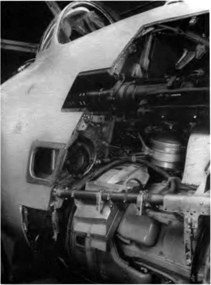
proposed a revolutionary rearrangement of the cannons. He built a sin­gle tray for the three cannons, ammunition boxes, cartridge cases, and link outlet ports. This tray was embedded under the nose and could be lifted or lowered by four cables controlled by a hand crank, a drive shaft, and four pulleys—like a small service elevator. The idea seemed so inspired that it was immediately approved for use on the 1-310 The system made the cannons easier to load and service and also reduced the aircraft’s turnaround time when missions had to be flown at close intervals.

The front part of the S-01 was modified to accommodate this tray. Finished at last, the S-01 was rolled out on 27 November 1947 and made its maiden flight on 30 December with test pilot V. N. Yuganov at the controls. But right away sizable losses of thrust were recorded, and all flights had to be canceled. To remedy these losses, TsAGI and TsLAM engineers proposed reducing the length of the fuselage and the exhaust pipe slightly. This change necessitated modifications to the ailerons, the wing chord, and the sweep angles of the tail unit (which were increased). The well-known silhouette of the MiG-15 was not cre­ated in one pass.

The second prototype or S-02 joined the test program before long and flew for the first time on 27 May 1948, powered by a 2,225 daN (2,270 kg st) Rolls-Royce Nene II The state trials of the S-01 and S-02 were carried out at the GK Nil WS in two stages, from 27 May to 25 August and from 4 November to 3 December. The report concluded, “The 1-310 has passed its state acceptance trials; its performance was in accordance with calculations; and the preparation of the preliminary design for a two-seat version for pilot training [the UTI MiG-15] is rec­ommended." Test pilots who flew the 1-310 were unanimous in their praise of the aircraft’s handling characteristics while taking off, climb­ing, and landing as well as its steadiness in flight and its maneuverabili­ty. In August 1948 the council of ministers of the USSR decided to order the 1-310 for the WS. It was given the military designation MiG-15.

The following details refer to the S-01.

Specifications

Span, 10.08 m (33 ft 1 in); overall length, 10.102 m (33 ft 1.7 in); fuse­lage length, 8 125 m (26 ft 7.9 in); wheel track, 3.852 m (12 ft 7.6 in); wheel base, 3.075 m (10 ft 1.1 in); wing area, 20.6 m2 (221.7 sq ft); empty weight, 3,380 kg (7,450 lb); takeoff weight, 4,820 kg (10,623 lb); fuel, 1,210 kg (2,667 lb); oil, 35 kg (77 lb); wing loading, 234 kg/m2 (48 Ib/sq ft); operational limit load factor, 8.

image118

Performance

Max speed, 1,042 km/h at 3,000 m (563 kt at 9,840 ft); max speed at sea level, 905 km/h (489 kt); climb to 5,000 m (16,400 ft) in 2.3 min; to

10,0 m (32,800 ft) in 7.1 min; landing speed, 160 km/h (86 kt); ser­vice ceiling, 15,200 m (49,855 ft); endurance at 10,000 m (32,800 ft), 2.01 h; range, 1,395 km at 12,000 m (866 mi at 39,360 ft); takeoff roll, 725 m (2,380 ft); landing roll, 765 m (2,510 ft).

1320 / R1/R-2/R 3

Toward the end of the 1940s a specification was laid down calling for a cover interceptor, a fighter whose role would be to oppose any invad­ing aircraft as far as possible from its target and under any weather conditions. Several manufacturers put in a tender for the program:

image147

The 1-320 (R-1) was designed for the cover-interceptor mission and was powered by two RD-45F engines.

Sukhoi, Mikoyan, Lavochkin, and (later) Yakovlev. This is how a num­ber of famous aircraft were created, including the Su-15 (the first of two), La-200, and La-200B. In this instance the result was the 1-320, an all-weather fighter proposed and built by Mikoyan in 1949.

This twin-jet had a cantilever midwing with a 40-degree sweep angle at the leading edge, and its tail unit was also swept back. Because this aircraft was designed at the same time as the MiG-15 and MiG-17, the family resemblance will come as no surprise. However, the 1-320 outdid both of them in size as well as weight. It differed from them in its side-by-side cockpit layout (one captain and one pilot/radar opera­tor) and its unusual power plant arrangement (two tandem-mounted turbojets in the fuselage). Its fuselage was 1.9 m (6 feet, 2.8 inches) in diameter with a maximum cross section of 2.83 m2 (30.4 square feet) The crew had dual controls and was equipped with two radar scopes. This certainly made the pilot’s job easier in combat, since the second crew member could scan the invaders or even fly the aircraft during the long defensive patrol flights. Each pilot had his own oxygen supply, and the overall reserve amounted to 6 1 (1.6 US gallons).

Both bladder fuel tanks—capacities 1,670 1 (441 US gallons) and 1,6301 (430 US gallons)—were placed behind the cockpit. The rear tank included a 45-1 (12-US gallon) antigravity feeder tank that supplied fuel

image148

The R-l had two tandem-mounted turbojets. The front engine’s exhaust nozzle emerged from the underside of the fuselage, while the rear engine’s nozzle came out under the tail.

image149

The R-2 differed from the R-l by its engines—two VK-1 turbojets—and its strengthened armament.

image150

The R-2 cockpit canopy was deeper than that of the R-l.

to the engines during inverted flights. It was also planned to equip the aircraft with two 750-1 (198-US gallon) drop tanks beneath the wings.

The front engine was located beneath the crew compartment, its exhaust nozzle emerging from the underside of the fuselage. The other engine was placed in the conventional position at the rear of the fuse­lage, its straight exhaust nozzle emerging from under the fin. The air­brakes flanked the tail section (area per unit, 1.08 m2 [11.6 square feet]; maximum deployment angle, 45 degrees).

The trailing edge of the wing was fully occupied in the inner sec­tion by Fowler flaps designed by TsAGI (span, 3.18 m [10 feet, 5.2 inch­es]; area per unit, 3.1 m2 [33.4 square feet]; takeoff setting, 22 degrees; landing setting, 56 degrees) and in the outer section by internally bal­anced ailerons (span, 2.497 m [8 feet, 2.3 inches]; area per unit, 1.47 m2 [15.8 square feet]). Both R-l and R-2 prototypes had four fences on the upper surface of the wing. To compensate for the retroaction of the rudder and the transverse instability it caused, 900-mm (2-foot, 11.5- mch) spoilers were installed on the wing’s lower surface. Operated by electric actuators, they could be extended 40 millimeters downward. Spoiler extension was automatic whenever the rudder deflection exceeded 2 degrees. The stabilizer had a sweep angle of 40 degrees at the leading edge, while the tail fin had a sweep angle of 59 degrees, 27

image151

minutes at the leading edge. The maximum deflection angle of the ele­vator was 33 degrees upward and 17 degrees downward. The maxi­mum deflection angle of the rudder was plus or minus 24 degrees, 48 minutes.

The tricycle landing gear was hydraulically controlled, with air – and-oil shock absorbers on the legs of the main gear. They retracted into the wing, and their wheels were fitted with double brake shoes and 900 x 275 tires. The front leg and its wheel (520 x 240 tires, no brakes) retracted forward. The wheel doors, flaps, airbrakes, and booster cylin­ders for the aileron and the elevator were also hydraulically controlled. The hydraulic reservoir had a capacity of 35 1 (9 US gallons). The dual pneumatic system consisted of a main circuit that controlled the wheel brakes and the cannon loading plus a standby system that governed the gear, flaps, and wheel brakes Fire control was electrical, activated by one button on the captain’s stick.

The first prototype, or R-l, was powered with two 2,225-daN (2,270- kg st) RD-45F turbojets. The R-2 and R-3 (in fact, a modified R-2) fea­tured 2,645-daN (2,700-kg st) VK-1 turbojets. The air intake was divided into three ducts: the one in the middle fed the front jet, and the other two channeled air to the rear jet The 1-320 could fly and even take off on either of its two engines. The polystyrene dome that housed the Toriy-A radar designed by A В Slepushkin was located in the upper lip of the air intake. The armament comprised two N-37 cannons flanking the air intake.

The R-l was rolled out in April 1949 and made its first flight on 16 April with Ya I Vernikov and S Amet-Khan at the controls. Factoiy tests continued until 18 January 1950 under two pilots, A N. Cher – noburov and 1. Y Ivashchenko. The R-l was also flown by four LII pilots—Ya. I. Vernikov, S. Amet-Khan, S. N. Anokhin, and M. L. Gal – lai—and by pilots of the PVO, a potential customer. Lt. Gen. Ye. Ya. Savitskiy, commanding officer of the PVO’s fighter regiments, made the following comments after flying the 1-320 ‘The aircraft handles well at takeoff, in flight, and while landing. It has no tendencies to yaw­ing or swinging. Being easy to handle, it can be flown by average pilots." The official test report added:

The aircraft has excellent in-flight steadiness on its three axes. Given the aircraft’s layout and the location of its fuel tanks, there is no need to use the elevator’s tab in a flight envelope ranging from takeoff speed to 700 km/h [378 kt]. Gear extension and retraction do not modify the aircraft trim. When performing a tight turn or a combat half-flick roll, the 1-320 handling character­istics remain safe. The airframe was initially stressed with a load factor of up to 5.9 for an aircraft weight of 8,530 kg [18,800

image152

The R-2 radome, like that of the R-l, housed a Toriy-A radar. Note the partitions in the air intake, to supply air to both engines.

pounds]. The load factor was later increased to 8. To test the radar’s performance fourteen flights were carried out, nine of which involved targeting a Tu-2, an Li-2, a B-17, or a Tu-4. While trying to intercept a Boeing B-17 Flying Fortress, the 1-320 was caught in the propeller slipstream of the bomber, causing the fighter to make a spectacular pirouette.

Yu. A. Antipov, M. L. Gallai, N. P. Zakharov, and G. T. Beregovoy were four of the pilots who took part in the combat tests. The R-l was not certified because of its transverse instability in a narrow speed range between Mach 0.89 and 0.9, and also because of its wing drop­ping between 930 and 940 km/h (502 and 508 kt).

image153

The 1-320 (R-2) was modified after an accident, becoming the R-3. Note the third wing fence.

The VK-1 engine of the R-2 prototype boosted the maximum speed by only 3 percent—1,090 km/h (589 kt) IAS versus 1,040 km/h (562 kt) for the R-l —considering the severe limitations imposed by the stiffness problems of a thin, high-aspect-ratio swept wing. Except for its new engines, the R-2 was not greatly modified. The crew’s all-around visibil­ity was improved, and the canopy was fitted with a more reliable emer­gency release system. The wing and the stabilizer were equipped with deicers, and the air intake ducts were electrically warmed. Its arma­ment was supplemented by another cannon so that the prototype field­ed a total of three N-37s, one on the left and two more on the right of the lower nose section.

The R-2 received its Toriy-A radar at the beginning of its test pro­gram. It was later replaced by a Korshun, also developed by Sle – pushkin. Neither radar was able to track targets automatically. The R-2 was equipped with an RV-2 radio-altimeter, an RSIU-6 VHF transceiver, and a Bariy (barium) IFF system.

This second prototype was rolled out in early November 1949. Dur­ing its factory tests from December 1949 to September 1950 the aircraft made 100 flights, executed a steep spin, jettisoned its canopy in flight, performed several aerobatic maneuvers under negative gravity, flew at night, and dropped its auxiliary tanks. Between 13 and 30 March all test flights had to be suspended after a shell exploded in an ammunition belt and damaged the aircraft’s nose. The OKB took advantage of the repair time to make a few modifications. The wing anhedral was reduced to 1.5 degrees from 3 degrees, the span of the spoilers was increased to compensate for the transverse instability at high speeds,

image154

flipper tanks were tested on the 1-320 (R-3).


The exhaust nozzle breaches and fin of the R-2/R-3 were somewhat different from those of the R-l


image155

an automatic airbrake deployment system was installed, and two fences were added on the upper surface of the wing. This repaired and modified R-2 became the R-3.

The first flight of the new version took place on 31 March. The test pilot noted that the wing anhedral modification had changed the trans­verse stability/yaw stability ratio. To deal with that problem a provi­sional ventral fin was added under the tail section. Moreover, the spoil­ers were mechanically linked to the ailerons. The tests were resumed on 13 April and ended on 23 April 1951. During the state trials sixty flights were made and the R-3 logged forty-five hours and fifty-five minutes in the air. All of these tests were carried out within certain operational limitations: speed, 1,000 km/h (540 kt); Mach, 0.95, load factor, 7.5; maximum speed with underslung tanks, 800 km/h (432 kt); load factor with underslung tanks, 3 5. The VK-1-powered I-320R-3 was not certified either—nor was its competitor, the Lavochkin La-200. As the saying goes, opportunity makes the thief; it was a third manufactur­er, Yakovlev, that—despite its late entry into the competition—gath­ered the fruits of much hard labor His Yak-25M equipped with RP-6 Sokol radar was selected for mass production. The R-l and R-2/R-3 were used for a long time as test beds for new equipment; for example, from 13 July to 31 August 1950 LII test pilot Sultan Amet-Khan made thirty-one flights to develop the Materik and Magniy-M instrument landing systems.

The following details refer to the I-320R1

Specifications

Span, 14.2 m (46 ft 7 in); length, 15.775 m (51 ft 9 in); fuselage length without radome, 12 31 m (40 ft 6 6 in); wheel track, 5.444 m (17 ft 10.3 in); wheel base, 4.754 m (15 ft 7.2 in), wing area, 41.2 m2 (443.5 sq ft); empty weight, 7,367 kg (16,237 lb); takeoff weight, 10,265 kg (22,625 lb); fuel, 2,700 kg (5,950 lb); wing loading, 249.2 kg/m2 (51.1 Ib/sq ft); max operating limit load factor, 8.

Performance

Max speed, 994 km/h at 10,000 m (537 kt at 32,800 ft); max speed at sea level, 1,040 km/h (562 kt); climb to 5,000 m (16,400 ft) in 2.3 min; to 10,000 m (32,800 ft) in 5.65 mm, service ceiling, 15,000 m (49,200 ft); range, 1,100 km (683 mi); takeoff roll, 610 m (2,000 ft); landing roll, 770 m (2,525 ft).

The following details refer to the I-320R-2/R-3 Specifications

Dimensions and area identical to R-l; takeoff weight, 10,725 kg (23,638 lb); max takeoff weight, 12,095 kg (26,657 lb); fuel, 2,700 kg (5,950 lb); fuel with two 750-1 (198-US gal) underslung tanks, 3,950 kg (8,705 lb); wing loading, 260.3-293.6 kg/mz (53.4-60.2 lb/sq ft).

Performance

Max speed, 1,090 km/h at 1,000 m (589 kt at 3,280 ft); max Mach, 0.9; service ceiling, 15,500 m (50,840 ft); range, 1,205 km at 10,000 m (748 mi at 32,800 ft); range with two 750-1 (198-US gal) underslung tanks, 1,940 km (1,205 mi).

1-360 / SM 2/SM 2A/SM 2B

To develop a fighter capable of supersonic speeds in level flight, many requirements had to be met:

—the layout had to have the smallest possible master cross-section to reduce drag

—the drag of the wing and the tail assembly had to be reduced by increasing their sweep angle at the leading edge —a series of intricate technical problems had to be resolved in designing duplicate flying controls, artificial feel systems, super­sonic air intakes, and the like

—the engines and fuel systems had to be positioned to prevent flameouts during maneuvers within the aircraft’s speed and alti­tude range, including when firing the cannons

The SM-2 became the flying laboratory that allowed engineers to explore ways to get beyond the sound barrier.

The SM-2 was designed in record time under the supervision of A. G. Brunov, deputy chief constructor, and R. A. Belyakov, who was then

image191

The SM-2 no 01 before being modified with its T tail.


The same SM-2 after modification of its tail unit. The stabilizer was lowered to the base of the fin to avoid the wing-blanketing effect.


image192

image193

The SM-2 no. 02, built at the same time as no. 01 also had a stabilizer set high on the fin

chief of the general affairs brigade. A. A. Chumachenko took care of the aerodynamic design while V. M. Yezuitov studied pilotage and han­dling problems. Engineer A V Minayev played a great part in the development of the SM-2. G. Ye. Lozino-Lozinskiy was put in charge of the power unit. The stress analysis was placed under the management of D. N. Kurguzov, who had worked with N N. Polikarpov before World War II.

The first SM-2 was a midwing, T-tail, twin-jet fighter. The wing sweep back C/4 was 55 degrees with a 4-degree, 30-minute anhedral. The sweep of the stabilizer and fin leading edges was 55 and 56 degrees, respectively. The wing structure was identical to that of the I – 350 (M) except that there were only two fences on the wing’s upper surface. Armament consisted of two N-37D cannons located in the lead­ing edge, near the wing roots. Rolled out in April 1952, the SM-2 made its first flight, with G. A. Sedov in the cockpit, on 24 May.

It soon became obvious that the aircraft could not really exceed Mach 1 in level flight. It did reach Mach 1.19—but in a shallow dive. At 3,920 daN (4,000 kg st) the cumulative thrust of the two first-series AM – 5A turbojets was not sufficient because they lacked an afterburner. The engines were replaced by reheated AM-5Fs—first developed for the SM-1—rated at 2,645 daN (2,700 kg st). Other faults were noted in the aircraft’s aerodynamic qualities and fuel control system.

image194

1-360 (SM-2) (MiG ОКБ three-view drawing)

image195

The spin problem was solved by moving the stabilizer to the base of the fin and modifying the location of the wing fences. Various other changes put a stop to engine flameouts and surges. After completing its factory tests, the SM-2 commenced its state trials in early 1953 They proceeded normally until V. G. Ivanov, a military pilot, discovered a serious shortcoming: a pitch instability caused by diminution of the sta­bilizer’s efficiency at high speeds. The flight tests were canceled, and the prototype was returned to the factory for modifications. The stabi­lizer was lowered once more and positioned on the rear section of the fuselage. The tailplanes on MiG fighters have remained on the fuselage and "abandoned” the fin ever since. Moreover, to suppress the buffet­ing caused by their deployment, the airbrakes were brought closer to the wing and lowered in relation to the fuselage datum line.

Once modified, the SM-2 became the SM-2A and later the SM-2B. The aircraft resumed its state trials in the summer of 1953. In fact, two SM-2s were built. In light of the test results both prototypes received the same modifications, especially those involving the stabilizer.

Specifications

Span, 9.04 m (29 ft 7.9 in); overall length, 13.9 m (45 ft 7.2 in); fuselage length, 10.285 m (33 ft 8.9 in); height, 3.95 m (12 ft 11.5 in); wheel

image196

The stabilizer also had to be lowered to the base of the fin on SM-2 no. 02


Among other modifications, the wing fences on SM 2 no. 02 were given a deeper chord


image197

image198

Reengined with two AM-9Bs, the SM-2B became the SM-9/1—true prototype of the MiG-19

track, 4.156 m (13 ft 7.6 in); wheel base, 4.398 m (14 ft 5.2 in), takeoff weight, 6,820 kg (15,030 lb).

Design Performance Mach limit, 1.19

1-380 /1-3

The 1-3 was a logical follow-on for the 1-1/1-2 design philosophy among various single-engine fighters developed simultaneously with other types such as the MiG-19 that were already being mass-produced Its design and structure were based on standard concepts shared by most other fighters of that time – all-metal structure, highly swept (over 50 degrees) and lift-augmented wing, airbrakes plus tail chute, powerful reheated turbojets, ejection seat, flying controls with artificial feel and gear ratio on the pitch channel, all-purpose on-board systems, and heavy armament (cannons)

The preliminary design of the 1-3 (1-380) frontline fighter, mapped out around the new Klimov VK-3 turbojet, was completed in March 1954 The VK-3 possessed an axial flow compressor, an annular com­bustion chamber, and an afterburner It was rated at 5,615 daN (5,730

г


image231

kg st) of design nominal thrust and 8,270 daN (8,440 kg st) with after­burner. The I-3’s stabilator and aileron power units were of the irre­versible type. On the other hand, the rudder servo-control units were reversible. The wing had a sweepback of 60 degrees С/4. The airbrakes covered an area of 1.2 m2 (12.9 square feet) and flanked the fuselage just behind the wing root. Their role was not only to shorten the land­ing roll and to improve the aircraft’s handling in level flight but also to reduce the aircraft’s speed during a full-power vertical dive. The PT 2165-511 tail chute was 15 m2 (161.5 square feet) in area. Armament consisted of three NR-30 cannons, two on the right and one on the left in the leading edge near the wing root. The pilot was protected by a 65- mm-tbick bulletproof windshield, a 10-mm armor plate in front of the cockpit, and a 16-mm armor plate in the seat back and headrest. Devel­opment of the turbojet was delayed several times by technical prob­lems; as it turned out, the 1-3 was never powered by the VK-3 and was later converted into an 1-3U.

Specifications

Span, 8.978 m (29 ft 5.5 in); overall length, 14.83 m (48 ft 0.8 in); fuse­lage length (except cone), 12.275 m (40 ft 3.3 in); wheel track, 4.036 m (13 ft 2.9 in); wheel base, 5.04 m (16 ft 6.4 in); wing area, 30 m2 (322.9 sq ft); empty weight, 5,485 kg (12,090 lb); takeoff weight, 7,600 kg (16,750 lb); max takeoff weight, 8,954 kg (19,735 lb); fuel, 1,800 kg (3,970 lb); oil, 32 kg (70 lb); wing loading, 253.3-298.5 kg/m2 (51.9-61.2 Ib/sq ft); max operating limit load factor, 9.

Performance

Max speed, 1,274 km/h (688 kt) at sea level; 1,311 km/h at 5,000 m (708 kt at 16,400 ft); 1,775 km/h at 10,000 m (958 kt at 32,800 ft); climb to 5,000 m (16,400 ft) in 0.81 min; to 10,000 m (32,800 ft) in 1.9 min; service ceiling, 18,800 m (61,660 ft); landing speed, 190 km/h (103 kt); endurance, 1 h 46 min; range, 1,365 km (848 mi); takeoff roll, 390 m (1,280 ft); landing roll, 726 m (2,380 ft).

MiG-21F / Ye-GT / Tip 72

Introduced in 1958, the MiG-21F (Ye-6T) was the first production model of the family. The delta wing had a 57-degree sweepback at the leading edge like the preceding delta-wing prototypes, with Fowler flaps designed by TsAGI. The power unit was the R-11F-300 turbojet, rated at 5,625 daN (5,740 kg st) of reheated thrust. Its control system could set the air intake shock cone in three different positions. It was thus possible to change the cross-section area of the air intake duct as well as the direction of the shock waves according to flight regime. Its military instrumentation was still relatively basic, limited to the ASP – SDN gunsight, the SRD-5 ranging radar, and the IFF transponder.

The Ye-6T 3, the third MiG-21 F prototype, was used to test canard surfaces.

There was no automatic direction finder. The curtain-type ejection seat was identical to that of the MiG-19. The tail chute was housed in a small container under the rear of the fuselage. The ten fuel tanks—six in the fuselage and four in the wing—had a total capacity of 2,160 1 (570 US gallons).

Armament included two NR-30 cannons with sixty rounds per gun and store stations under the wing for two UB-16-57U rocket pods with either sixteen 57-mm S-5M air-to-air rockets (ARS-57) apiece or sixteen 57-ram S-5K air-to-surface rockets (KARS-57); two 240-mm ARS-240 heavy air-to-surface rockets; or two 50- to 500-kg (110- to 1,100-pound) bombs. The third prototype, the Ye-6T/3, was tested with a small mobile canard surface set near the nose; this foreplane was to appear later on the Ye-8 experimental machine. The Ye-6T/3 was also used to develop the launching system of the air-to-air missiles that were to arm future versions of the MiG-21.

Tests of the MiG-21F ended in 1958. Forty machines were assem­bled in the Gorki factory in 1959 and 1960

Specifications

Span, 7.154 m (23 ft 5.7 in); length (except probe), 13.46 m (44 ft 1.9 in); fuselage length (except cone), 12.177 m (39 ft 11,4 in); wheel track, 2.692 m (8 ft 10 in); wheel base, 4 806 m (15 ft 9.2 in), wing area, 23 m[3] [4] (247.6 sq ft); takeoff weight, 6,850 kg (15,100 lb); fuel, 1,790 kg (3,945 lb); wing loading, 297.8 kg/m2 (61 lb/sq ft); max operating limit load factor, 7.

Performance

Max speed, 2,175 km/h at 12,500 m (1,175 kt at 41,000 ft); max speed at sea level, 1,100 km/h (594 kt); climb rate at sea level in clean con­figuration, 175 m/sec (34,450 ft/mm); climb to 18,500 m (60,700 ft) in 7.5 min; service ceiling, 19,000 m (62 300 ft); landing speed, 280 km/h (151 kt); range at 14,000 m (45,900 ft) in clean configuration, 1,520 km (945 mi); takeoff roll, 900 m (2,950 ft); landing roll with tail chute, 800 m (2,625 ft).

IWiG-21US / 7///Б8 / Ye-33 / Ye-ББВ

The MiG-21US two-seat training aircraft was derived from the MiG-21 U and differed externally in two points: the chord of the tail fin was broader, and the parachute container was located at the base of that fin. However, the most significant modifications were inside the air­craft. It was powered by the R-11F2S-300 turbojet rated at 6,050 daN (6,175 kg st) and consequently had the SPS system. Because the cone had no radar to house, there was no need to increase the diameter of the air intake, so the diameter remained at 690 mrn (27.2 inches). The total capacity of the fuel tanks increased to 2,4501 (647 US gallons) and

The MiG-21 US differed from the MiG-21U in two particulars it had a broader-chord tail fin, and the tail chute canister was moved to the base of the vertical tail surfaces

the SK ejection seats were replaced by the KM-1M (SK-3) model The MiG-21 US was mass-produced for the VVS and for export in the Tbilisi factoiy between 1966 and 1970

A M1G-21US also renamed Ye-33 and piloted by S Ye, Savitskaya broke four female world records on 6 June 1974

1 Time to climb to 3,000 m (9,840 feet), 59,1 seconds

2 Time to climb to 6,000 m (19,680 feet), 1 minute, 20.4 seconds

3, Time to climb to 9,000 m (29,520 feet), 1 minute, 46.7 seconds

4. Time to climb to 12,000 m (39,360 feet), 2 minute, 35.1 seconds

Another MiG-21US renamed Ye-66B and piloted once more by S Ye. Savitskaya topped those four records comfortably on 15 November 1974. [6] 2 [7] [8]

In the documents sent to the FAI to verify those records, it was mentioned that the Ye-66B was powered by one RDM at 6,860 daN (7,000 kg st) and two TTRDs at 2,250 daN (2,300 kg st). Those mysteri­ous acronyms had to be deciphered; it was surmised that the RDM was in fact the R-11F2S-300 turbojet (somewhat revved up by toying with the engine combustion temperature and rotation speed) and that the TTRDs were two SPRD-99 solid rocket boosters for help at takeoff.

Specifications

Span, 7.154 m (23 ft 5.7 in); fuselage length (except cone and probe),

12.18 m (39 ft 11.5 in); wheel track, 2.692 m (8 ft 10 in); wheel base,

4.806 m (15 ft 9.2 in); wing area, 23 m[9] [10] (247.6 sq ft); takeoff weight, 8,000 kg (17,630 lb); fuel, 2,030 kg (4,475 lb); wing loading, 347.8 kg/m2 (71.3 Ib/sq ft); max operating limit load factor, 7.

Performance

Max speed, 2,175 km/h at 13,000 m (1,175 kt at 42,640 ft); max speed at sea level, 1,150 km/h (621 kt); climb rate at sea level (half internal fuel, full thrust) with two R-3S missiles, 115 m/sec (22,640 ft/min); climb to 17,200 m (56,415 ft) in 8 min; service ceiling, 17,700 m (58,055 ft); landing speed, 250-260 km/h (135-140 kt); range, 1,210 km at 14,000 m (750 mi at 45,920 ft), with 800-1 (211-US gal) drop tank, 1,460 km (905 mi); takeoff roll, 900 m (2,950 ft); landing roll with SPS and tail chute, 550 m (1,800 ft).

MiG 27D / 32 27 MiG27M/3223 MiG 27L / 32 29L

These three versions were the most advanced of the MiG-27 family. They were all equipped with the upgraded PrNK~23M nav-attack sys­tem, which improved their operating range significantly. Their weaponry includes various containers such as the three-camera recon­naissance pod or SPPU-22 gun pods (for the 23-mm twin-barrel depressible cannon with 260 rounds).

The MiG-27D was equipped with the Klen ("maple") range finder (much more efficient than the MiG-23’s Fone). The MiG-27L (32-29L) was the export version of the МЮ-23М and is built under license by India’s HAL as the Bahadur (“valiant"). Production of 165 machines was launched there in 1984; it seems very likely that this number will increase.

MIG-29S / MiG 29SE / 913

The first modified version of the basic model was produced concur­rently and became operational in the same units that received the standard fighter. Known at first as the izdeliye 9-13 (the OKB’s internal name), the MiG-29S was first flown on 23 December 1980 with V. M. Gorbunov at the controls.

The only external differences from the MiG-29 are a slightly hump­backed dorsal spine behind the cockpit to hold additional avionics and a bigger no. 1 tank with a capacity of 780 1 (206 US gallons). The com­puter-controlled leading edge flaps are divided in five segments, instead of the four on the MiG-29. But the MiG-29 differs from its prede­cessors in many other aspects as well:

—the conventional flying controls were optimized to increase the AOA operating range (up to 28 degrees), to augment the aircraft’s steadiness in flight and controllability at high AOAs, and to move back the trigger level of unintentional stalls and spins —this new version could carry under the wings two jettisonable extra fuel tanks having a capacity of 1,150 1 (304 US gallons)

The first variant of the MiG-29, the MiG-29S differs from the basic aircraft by its some­what humpbacked fuselage and the wing that is piped for two 1,150-1 (304-US gallon) drop tanks

The louvers that partly feed the engines while the aircraft is taking off or landing are covered in this photograph by protective equipment. Compare the wing thickness at the leading edge with that of the МЮ-29М.

The weaponry fitted to the wing of this sixth prototype of the MiG-29M comprises four Kh-31P air-to-surface missiles under the inner panels, and two RW-AE and two R-73A air-to-air missiles under the outer panels.

Unlike the MiG-29 and MiG-29S, the MiG-29M has no louvers above the leading edge root extensions. The sharp leading edge of the wing should be compared with that of the MiG-29S.

This photograph of the МІС-29М shows some of the distinctive features of this version: the “fat back,” the deeper cockpit canopy and the notched tailplane of greater area.

Located in front of the windshield, the ball that houses the OLS-M system (protected by a removable fairing on nonoperational flights) differed in shape from that of the MiG-29S.

apiece, bringing the aircraft’s overall fuel capacity to 8,2401 (2,177

US gallons) and its maximum range to 2,900 km (1,800 miles)

The weapons load was increased to 4,000 kg (8,800 pounds) The MiG-29S can carry most of the MiG-29’s weaponry but is wired for new armament such as the new RW-AE medium-range active air-to-air mis­siles or other R-27E semiactive and IR homing air-to-air missiles offer­ing improved range It can also carry four B-13 rocket pods that can each fire five 122-mm S-13T or S-130F munitions The aircraft is capa­ble of engaging two targets simultaneously with its active and IR hom­ing missiles and of firing its GSh-301 cannon when fitted with the underbelly tank The N 019M radar is of the coherent pulse-Doppler type, an improved version of the RP-29 that has a built-in test set but no mapping mode

The MiG-29SE is the export version of the MiG-29S. Its radar unit is the N 019ME, a somewhat downgraded version of the N 019M.

The dimensions and wing areas of the MiG-29 and the MiG-29S are identical The only difference is the weight: takeoff weight of the MiG – 29S is 15,300 kg (33,730 pounds), and its maximum takeoff weight is 19,700 kg (43 430 pounds) The overall performance of both aircraft is identical as well except for the maximum range, which on the MiG-29S reaches 2,900 km (1,800 miles) when the aircraft is fully fueled with the internal tanks (4,440 1 [1,173 US gallons]), the underbelly tank (1,500 1 [396 US gallons]), and the wing drop tanks (2,300 1 [608 US gal­lons]) All operational MiG-29s can be updated to the 9-13 (MiG-29S) standard

MiG-15 /1310 / S-03

The S-03 prototype was built in March 1948 within the context of the test program. Nearly all of the shortcomings found in the first two pro­totypes were eliminated on the S-03 under the supervision of chief engineer A. A. Andreyev, who was in charge of the program. Like the S-02, the S-03 was powered by a Nene II. But it differed from the S-02 in many other respects:

—it was equipped with hydraulically powered airbrakes hinged on the fuselage tail section (the rear structure had to be strengthened for this purpose)

— the stabilizer was moved 150 millimeters (5.9 inches) aft to improve its efficiency (this change necessitated a modification of the tail fin)

—the elevator was fitted with balance weights —the canopy was attached by a new latch mechanism —capacity of the no. 1 and no. 3 fuel tanks was reduced, limiting total fuel capacity to 1,450 1 (383 US gallons) from 1,538 1 (406 US gallons)

—two store points were added beneath the wing for auxiliary fuel tanks or bombs (FAB-lOOs, FAB-50s, or AO-25s)

—removal of the cannon fairings was simplified —new equipment was introduced, from an ASP-IN gunsight and an S-13 camera gun to a fire extinguishing system

The most serious challenge to be met with the S-03 was giving the wing structure adequate strength to comply with 1947 standards. This is why the new V-95 alloy was widely used for the wing structure (in place of D-16 duralumin) and 30-KhGSA chromansil steel for the spar webs and flanges. This structural reinforcement added 180 kg (397 pounds) to the weight of the wing. There were twenty-three ribs instead of twenty, and the skin was 1.8 mm thick instead of 1.5 mm. The efficiency of the aileron was improved by increasing the area from 0.96 m2 (10.3 square feet) to 1.17 m2 (12.6 square feet). The span of the

image119

The 1-310 S-03 was the master aircraft selected by the WS. But to be safe the air force also ordered a small number of La-15s, a competing fighter created by the Lavochkin OKB.

image120

The S-03 was equipped with airbrakes hinged on the rear fuselage. Their modest area of 0.52 m2 (5.6 square feet) had to be increased on production aircraft.

flaps was reduced slightly, but their chord was increased. The gear, air­brakes, and flaps were controlled by the hydraulic system with a no – load running valve. Switching on no-load running was automatic.

The S-03 was the first MiG aircraft that used its flaps for takeoff. That reduced takeoff roll to 695 m (2,280 feet) from the S-02’s 810 m (2,655 feet). But the airbrakes reduced the landing roll by only 30-35 m (98-115 feet). The prototype left the factory in March 1948 and was first flown on 17 June by I. T. Ivashchenko. The factory tests ended on 15 October (LI1 test pilot S. N. Anokhin came to assist Ivashchenko). The S-03 made a total of forty-eight flights, and all its flaws were eradi­cated one after the other. During one of these flights it reached a top speed of Mach 0.934. On 1 November the S-03 was sent to Saki, in the Crimean branch of the GK Nil WS, for another series of tests carried out by two military pilots, Yu. A. Antipov and V. G. Ivanov. They made thirty-five flights and spent fifteen hours and twenty-one minutes in the air, wrapping up their examination on 3 December. On 23 Decem­ber Marshall Vershinin, commander-in-chief of the WS, ratified the "acceptance trials report of the frontal MiG-15 single-seat fighter.” These are some of the report’s conclusions:

Considering its performance, we recommend choosing this air­craft to equip our squadrons, to prepare its series production and its availability for issue in compliance with the WS standards.

—this aircraft can be operated from rough strips — dogfight tests have not yet been carried out, but because of its high maneuverability it will be possible to involve the aircraft in fierce close combats —it can be flown inverted

—because of its handling characteristics, it can be flown by average pilots

The outstanding performance of the 1-310 S-03 (as well as the S-01 and S-02) in test flights was undoubtedly the reason that mass produc­tion was ordered by the Soviet government.

Specifications

Span, 10.085 m (33 ft 1 in); overall length, 10.102 m (33 ft 1.7 in); fuse­lage length, 8 125 m (26 ft 7.9 in); wheel track, 3.852 m (12 ft 7.6 in); wheel base, 3.075 m (10 ft 1.1 in); wing area, 20.6 m2 (221.7 sq ft); empty weight, 2,955 kg (6,513 lb); takeoff weight, 4,806 kg (10,592 lb); pilot, 97 kg (214 lb); fuel, 1,210 kg (2,667 lb); oil, 40 kg (90 lb); ammu­nition, 117 kg (258 lb); removable equipment, 35 kg (77 lb); wing load­ing, 233.3 kg/m2 (47.8 lb/sq ft); max operating limit load factor, 8.02.

Performance

Max speed, 1,031 km/h at 3,000 m (557 kt at 9,840 ft), 983 km/h at

10.0 m (531 kt at 33,800 ft); max speed at sea level, 905 km/h (489 kt); climb to 5,000 m (16,400 ft) in 2.3 min; to 10,000 m (32,800 ft) in 7.1 min, landing speed, 160 km/h (86 kt); service ceiling, 15,200 m (49,850 ft); range of S-03 at 1,000 m (3,280 ft), 660 km (410 mi); at

5.0 m (16,400 ft), 908 km (564 mi); at 12,000 m (39,360 ft), 1,433 km (890 mi); range of S-02 at 1,000 m (3,280 ft), 695 km (432 mi); at 5,000 m (16,400 ft), 955 km (593 mi); at 12,000 m (39,360 ft), 1,530 km (950 mi); takeoff roll, 695 m (2,280 ft); landing roll, 710 m (2,330 ft).

MiG-17 Series

MiG-17 /1-330 / SI / MiG-15 bis 45° / SI 2/SI 02/SI 01

The next major challenge faced by MiG designers was to increase the maximum speed of a fighter solely by improving its aerodynamic fac­tor—that is, without giving it a single additional pound of thrust. Both in silhouette and in structure, the SI-2 (prototype of the MiG-17) and its double the SI-3 looked very much like the MiG-15. (The SI-1 was set aside for static tests and never left the ground.) But there were many important differences:

—the wing sweepback C/4 (at quarter chord) was 45 degrees from the root to midspan (hence the aircraft’s designation) and 42 degrees beyond that, creating a sweepback on the leading edge of 49 degrees and 45 degrees, 30 minutes (this compound sweep came about not only because of trim considerations but also because the wing root rib had to be bolted to a section of the fuse­lage inherited from the MiG-15)

—the wing area was enlarged by 2 m2 (21.5 square feet)

—the anhedral was increased to 3 degrees with a 1-degree wing inci­dence

image156

The Sl-2, the second 1-330 built, was the first prototype of the MiG-17 program to fly


Note the leading-edge compound sweepback—45 and 42 degrees at quarter chord—of the SI-2, plus its six wing fences.


image157

image158

First-senes MiG-17 (MiG OKB three view drawing)

—the wing had six fences

—the wing profile was thinner, with a TsAGI S-12s at the root and a TsAGI SR-11 at the tip (wing aspect ratio, 4 08; taper ratio, 1.23: mean aerodynamic chord, 2.19 m [7 feet, 2.2 inches])

—the wing-to-fuselage junction was improved near the trailing edge —the fuselage was lengthened hy 900 mm (2 feet, 11.5 inches) in proportion to the sweepback increase —the area of the airbrakes was increased to 1.76 m2 (18.9 square feet)

The semimonocoque fuselage was built in two parts that joined at the main wing-fuselage splice fittings to facilitate engine removal and replacement. The cockpit was pressurized and air-conditioned. The hood was made of a 64-mm-thick bulletproof glass windshield and a sliding canopy. In the lower part of the fuselage beneath the cockpit, an inspection panel allowed for easy access to the cannon tray The cockpit was equipped with a first-generation ejection seat controlled by handles on both armrests.

The monospar wing, reinforced with stiffeners and a stressed skin structure, had a 12-percent thickness ratio. The ailerons each had a span of 1 512 m (4 feet, 115 inches), an area of 0.8 m2 (8.6 square feet), and a maximum deflection angle of plus or minus 18 degrees, and they were balanced internally. The aileron on the right side was fitted with a tab measuring 0 034 m2 (0 37 square feet), and the aileron control was boosted by a hydraulic servo-control The Fowler-type flaps (span, 4 m [13 feet, 1.5 inches]; area, 2.86 m2 [30.8 square feet]) had two settings. 20 degrees for takeoff and 60 degrees for landing. The fin had a sweep angle of 55 degrees, 41 minutes at the leading edge and a total area of 4.26 m2 (45.85 square feet), including 0.947 m2 (10.2 square feet) for the rudder The horizontal tail—an ASA-M airfoil—had a sweep angle of 45 degrees at the leading edge and a total area of 3.1 m2 (33.37 square feet), including 0.884 m2 (9.5 square feet) for the elevator.

Two bladder tanks with capacities of 1,250 1 (330 US gallons) and 150 1 (40 US gallons) were located behind the cockpit. They could be placed in the fuselage via the cannon access port, and because of their location their contents had no effect on the aircraft’s trimming. Two store stations beneath the wing could receive either two drop tanks or two 100-kg (220-pound) or 250-kg (550-pound) bombs. Other equip­ment included the RSIU-3 Klen ("maple") VHF and the SRO-1 Bariy-M IFF transponder as well as the OSP-48 ILS, which included the ARK-5 Amur automatic direction finder, the MRP-48 Khrizantema (“chrysan­themum”) marker receiver, and the RV-2 Kristall low-altitude radio­altimeter. Its armament was identical to that of the MiG-15: one N-37D with forty rounds and two NR-23s with 80 rpg.

image159

Armament on the SI-2 is identical to that on the MiG-15 and MiG-15 bis The landing light in the air intake partition was later moved.


image160

The SI-02: third prototype built, second to fly, and first production-line MiG-17.


image161

The SI-02 with airbrakes deployed and flaps lowered at the landing setting

The SI-2 was flight-tested by I. T. Ivashchenko An in-depth test sequence was planned, including even the most difficult aerobatic maneuvers. From the start Ivashchenko noted that the SI-2 was 40 km/h (22 kt) faster than the MiG-15 bis, and on 1 February 1950 he reached 1,114 km/h (602 kt) in level flight at 2,200 m (7,215 ft). But 20 March proved to be a fateful day for the aircraft and its pilot. After com­pleting the day’s exercises at 11,000 m (36,080 ft), Ivashchenko started to descend normally when suddenly the aircraft dived and crashed.

After the tragic death of the pilot, it took more than a year to establish the causes of this accident, remedy them, and build a new prototype, the SI-02. (The SI-01, whose assembly was delayed, rolled out of the factory after the SI-02 and was thus the fourth prototype.) To test this machine Mikoyan called on a military test pilot, G. A. Sedov. The SI-02 passed its factoiy tests and state acceptance trials in short order. In decree no. 851 of 1 September 1951 the GK Nil WS and the ministry of aircraft production ordered mass production of the aircraft in no fewer than six factories (recall that the MiG-15 was built in eight factories).

The MiG-17 was able to carry out the most complicated aerobatic maneuvers, but it was necessary to impart a greater deflection to the control surfaces than was the case with the MiG-15 bis. Moreover, its

image162

The SI-01—fourth prototype built, third to fly—was rolled out after the SI-02, delayed by production problems. It carried two 400-1 (106-US gallon) slipper tanks.

acceleration after takeoff had deteriorated somewhat. With the help of its airbrakes the MiG-17 was able to roll at any speed or altitude up to

14,0 m (45,920 feet). The area of the airbrakes was increased slightly on the assembly line starting in September 1952.

At high altitudes the MiG-17 was a very stable aircraft. It was even possible to roll in at its operational ceiling without losing much alti­tude. However, at 270-280 km/h (146-151 kt) its gliding descent speed was significantly faster than that of the MiG-15 bis. Several modifica­tions were made on the assembly line to improve the aircraft’s struc­ture and safety. For instance, the ejection seat was fitted with a tight strap slinged to the pilot’s bucket. With that safety device the pilot was much better secured. And like the MiG-15, the left armrest of the pilot’s seat was equipped with a backup activator for the ejection seat in case the pilot’s right hand was wounded in flight. As early as the end of 1953, all MiG-17s were equipped with a more modern curtain-type ejection seat that could be used safely at various speeds. This seat— developed by MiG—protected the pilot’s face from the relative wind, was equipped with stabilizing panels meant to prevent a disorderly free-fall, and secured the pilot’s legs. The OKB also developed for the MiG-17 a one-piece canopy (without a rear arch) that improved the pilot’s field of vision in the rear to between 24 and 27 degrees on both

Performance Comparison of the MiG-17 and the My store IV

Aircraft

MiG-17

Mysore IV

Takeoff weight

5,200 kg (11,460 lb)

7,400 kg (16,310 lb)

Engine thrust

2,645 daN (2,700 kg st)

3,430 daN (3,500 kg st)

Maximum speed

1,114 km/h (602 kt)

1,090 km/h (589 kt)

Flight endurance

1 h 50 min

1 h 10 min

Armament

1 x 37 mm and 2 x 23 mm

2 x 30 mm

Source: MiG OKB

sides. Nevertheless, the rearward view—so important in a fighter—was not totally panoramic. That is why periscopes, the only piece of equip­ment that offered a 360-degree view, soon made their appearance.

The VK-1 turbojet generated the equivalent of 12,000 shaft horse­power (shp), ten times the power of the AM-35A piston engine of the first MiG aircraft. Before long the MiG-17 was equipped with the VK – 1A, which also delivered 2,645 daN (2,700 kg st) but had a much longer service life. The MiG-17 as well as the last series of the MiG-15 bis was fitted with a new starting system that could use either a ground power unit or an airborne storage battery, making the aircraft self-contained. However, the start cycle was longer in the self-contained mode (forty – four seconds versus thirty seconds). The fuel system was greatly improved by inserting a pressure relief valve in the drop tanks’ pres­surization pipes to ensure a regular flow of fuel at all operational speeds. Finally, the landing light was moved from the engine air intake to a place under the wing.

The SI-02 tests revealed a few structural shortcomings. For exam­ple, during one flight strong vibrations were felt in the elevator. By yanking and throttling back immediately Sedov thought he could stop the vibrations, but the elevator had already partly disintegrated. By trimming the aircraft on its glide path solely with the throttle, Sedov managed to return to the airfield and land. The cause of the vibrations was identified, and the aircraft was modified accordingly. Ever since, pilots have had nothing but praise for the performance of the MiG-17.

In tests two LII pilots, S. A. Anokhin and P. I. Kazmin, achieved Mach 1.14, a speed that was never used operationally.

At different times, nearly forty countries on three continents chose the MiG-17 for their air forces: Albania, Algeria, Afghanistan, Angola, Bulgaria, Cambodia, China, the Congo, Cuba, Czechoslovakia, East Ger­many, Egypt, Ethiopia, Finland, Guinea, Hungary, India, Indonesia, Iraq, Madagascar, Mali, Mongolia, Morocco, Mozambique, Nigeria, North Korea, Pakistan, Poland, Rumania, Sri Lanka, Somalia, the Sudan, Syria, Uganda, Vietnam, Yemen, and Yugoslavia. The aircraft has proven itself in combat, first in Egypt in the fall of 1956 against French Mystere IVs as well as British Vampires and Meteors. It is inter­esting to compare the characteristics of the MiG-17 with those of a con­temporary fighter, the Dassault Mystere IV (see table). In the early 1960s MiG-17s twice engaged American F-105 Thunderchiefs and F-4 Phantoms over North Vietnam.

From this basic airframe the MiG OKB developed a full range of tactical fighters for specific missions, endowing this aircraft with a great versatility. The MiG-17 has also been used as a testbed for a num­ber of systems intended for the next generation of fighters.

Specifications

Span, 9.628 m (31 ft 7 in); overall length, 11.264 m (36 ft 11.5 in); fuse­lage length, 9.206 m (30 ft 2,4 in); height with depressed shock absorbers, 3.8 m (12 ft 5.6 in); wheel track, 3.849 m (12 ft 7.5 in); wheel base, 3.368 m (11 ft 0.6 in); wing area, 22.64 m2 (243.7 sq ft); empty weight, 3,798 kg (8,371 lb); takeoff weight, 5,200 kg (11,460 lb); max takeoff weight, 5,929 kg (13,068 lb); fuel + oil, 1,173 kg (2,585 lb); wing loading, 230-262.3 kg/m2 (47.2-53.8 Ib/sq ft); max operating limit load factor, 8.

Performance

Max speed, 1,114 km/h at 2,000 m (602 kt at 6,560 ft); max speed at sea level 1,060 km/h (572 kt); Mach limit (fluttering conditions), 1.03; climb to 5,000 m (16,400 ft) in 2 min; to 10 000 m (32,800 ft) in 5.1 min; service ceiling, 15,600 m (51,170 ft); landing speed, 170-190 km/h (92-103 kt); range, 1,295 km at 12,000 m (805 mi at 39,360 ft); 1,185 km at 10,000 m (735 mi at 32,800 ft); range with two 400-1 (106-US gal) drop tanks, 2,150 km at 12,000 m (1,335 mi at 39,360 ft); 1,907 km at

10,0 m (1,184 mi at 32,800 ft); takeoff roll, 535 m (1,755 ft); landing roll, 825 m (2,700 ft).