Category FLIGHT and M ОТІOIM

NASA Advances

The Soviet successes pushed the U. S. government into funding the $20 billion Apollo program that aimed to land

THE PRESIDENT’S CHALLENGE

"I believe this nation should commit itself to achieving the goal, before this decade is out, of landing a man on the Moon and returning him safely to the Earth. No single space project. . . will be more exciting, or more impressive to mankind. . . and none will be so difficult or expensive to accomplish."

President John F. Kennedy addressing Congress, May 25, 1961

___________________ J

NASA Advances

О The United States launched its first satellite, Explorer 1, on a Jupiter rocket at Cape Canaveral, Florida, in January 1958. The Soviets had launched their first satellite a few months before.

astronauts on the Moon before the end of the 1960s. NASA successes and failures, broadcast live on television and radio, were very public. Soviet flights were revealed only after a successful launch. The Soviets made more headlines with the first two-person spacecraft, the first woman astronaut, and the first space­walk. With the U. S. Gemini program, however, NASA demonstrated essential space techniques, such as docking. U. S. computer and ground-tracking systems also were far ahead of Soviet electronics at the time.

THE HUMAN COST OF THE SPACE RACE

There were human casualties of the space race. Three U. S. astronauts were killed in a fire in January 1967 when they were trapped in their capsule as it caught fire during testing. The men were Apollo 1 crewmen Virgil Grissom, Roger Chaffee, and Edward White. Soviet cosmonaut Vladimir Komarov was killed in Soyuz 1 in April 1967. Three other Soviet cosmonauts (Georgi Dobrovolski, Viktor Patsayev, Vladislav Volkov) died in Soyuz 11, in 1971.

___________ J

By the mid-1960s, manned space­flights attracted huge public interest. The promise of Apollo overshadowed scientific missions by robot probes to the planets Mars and Venus, which were launched by both the Soviet Union and the United States.

By 1969, the Americans had a rocket to match the Soviet boosters: the mighty Saturn V, built to send Apollo to the Moon. Each Apollo test flight aroused high public excitement. The world was watching when, on July 20, 1969, the Apollo 11 lunar lander touched down on the Moon, and Neil Armstrong radioed a message to Earth: “Houston, Tranquility Base here. The Eagle has landed.”

Stability and Control

A

n airplane’s stability is its ability to correct itself when it is upset by turbulence or a gust of wind. The stability of an aircraft affects its performance, handling, and control in the air. Most airplanes are designed to be stable in all three dimensions: longi­tudinal stability (stability in pitch), later­al stability (stability in roll), and finally directional stability (stability in yaw).

Longitudinal and Lateral Stability

Longitudinal stability helps an airplane to stay level from nose to tail. This form of stability is provided by the aircraft’s horizontal stabilizers, or tailplanes. If a gust of wind pushes a plane’s nose up, the horizontal stabilizers produce more lift and raise the tail as well, keeping it level with the nose. If a gust pushes the nose down, the tail also dips.

Lateral stability helps to stop a plane from rolling, or banking, unless the pilot

wants it to roll. The wings provide the lateral stability. Most airplane wings tilt up at an angle from the fuselage to the wingtips, making a shallow V shape. This is called the wing dihedral. If the plane rolls to one side, one wingtip rises, and the other falls. The plane also begins to slide sideways toward the lower wing. As it starts to slide, air pushes back against it. The air resistance lifts the lower wing and levels the aircraft.

An airplane’s wings usually are con­nected to the plane at the bottom of the fuselage, but a few planes have wings that connect at the top of the fuselage. These wings do not have a dihedral shape. Instead, they are level or droop down a little. The drooping wing shape is the opposite of dihedral, and it is called negative dihedral or anhedral.

Подпись: vertica stabilizer

Stability and Control Stability and Control Подпись: (Directional stability)

Stability and ControlО This diagram shows the dihedral angle of the wing used in most airplanes. The angle provides lateral stability and keeps the aircraft from rolling during flight. The stabilizers in the tail provide longitudinal and directional stability.

Stability and Control

Подпись: О Early winged aircraft were highly unstable. This plane crashed near El Paso, Texas, in 1911.

This type of airplane gets its lateral stability from the weight of its fuselage. If the plane is pushed over into a roll by a gust of wind, the fuselage works like the heavy weight at the bottom of a pen­dulum and swings the plane back to an upright position. Hang gliders and microlight aircraft are stable for the same reason-the pilot’s weight hanging below the wing provides stability.

Synthetic Vision System

A

synthetic vision system (SVS) provides pilots with a clear image of the view from their air­craft in all weathers, flying conditions, and visibility levels. A typical system is composed of databases of information that create a virtual reality display in the cockpit. The systems, still in develop­ment, are being created to help pilots fly more safely.

Developing a Solution to Poor Visibility

A pilot’s mental image of his or her plane moving in relation to the ground is called situational awareness. If the pilot’s mental image is not the same as what is actually happening in the real world, the pilot has lost situational awareness. When an aircraft is near the ground, or flying near other air traffic, loss of situational awareness can prove
to be deadly. It can cause a plane to fly into an obstacle or lead to a midair col­lision. It can make a fighter pilot delay ejecting from an aircraft, which can be fatal. If an aircraft flies into an obstacle, or water, while under control, this is called Controlled Flight into Terrain, or CFIT. In general aviation, CFIT is the leading cause of accidents.

Synthetic vision systems are being developed to give the pilot a clear view of the surrounding ground, no matter how bad the visibility is. The research and development work is being carried out jointly by four NASA establish­ments—Langley Research Center, Ames Research Center, Dryden Flight Center, and Glenn Research Center in partner­ship with the FAA (Federal Aviation Administration) and the aviation indus­try. The research aims to cut fatal acci­dents by 80 percent in ten years and by 90 percent in twenty-five years by mak­ing every flight as safe and easy as a flight on a clear, sunny day.

An SVS improves a pilot’s situation­al awareness by creating a three­dimensional (3D) image of the ground below. The image is not from a camera—it is generated from a computer database stored in the aircraft. The database uses

О Poor visibility is a common factor in air accidents. A pilot often cannot see the ground clearly because of low cloud, fog, rain, or darkness. In such conditions, it is possible to fly dangerously close to moun­tains or other obstacles.

Подпись: rПодпись:

MEASURING EARTH’S SHAPE

The Space Shuttle Radar Topography Mission measured the shape of about 80 percent of Earth’s surface. It creat­ed an image of the ground below by using radar instead of light. Radar was used because it can see through clouds and make images at night. Two radar images of the same spot on the ground were taken every 100 feet (30 meters). The images were taken from slightly different points using two radar antennae. One was inside the Space Shuttle’s payload bay. The other was at the end of a 195-foot (59- meter) mast that extended from one side of the Space Shuttle. The differ­ences between the two images allowed the height of the ground to be calculated. This process is called inter­ferometry. The information allows a computer to generate a detailed map of Earth’s surface that shows the shape and height of the ground.

information that was collected by the Space Shuttle during the Space Shuttle Radar Topography Mission in 2000.

Creating Virtual Reality

The synthetic vision database does not just show Earth’s surface shape. It also contains details of obstacles such as bridges, towers, and pylons. A full-color

moving image appears on a flat panel display, like a computer screen, in the cockpit. The screen display looks like an image from a flight simulator computer game, but SVS is much more advanced than a game. It generates a 3D view of the ground in real time. As a plane flies along, GPS satellite navigation tells the synthetic vision system where it is. The image of the ground moves past just like the real view from the plane’s window, but the SVS image is always bright and clear whatever the weather conditions or time of day.

Weather information can be added to the image to show nearby storms. The screen also can display the correct approach path to an airport. This can make a difficult approach to an airport easier and safer to fly. When a plane is on the ground at an airport, the display

shows a plan of the airport. When the pilot is given permission to taxi, the ground controller’s directions can be sent straight to the plane’s synthetic vision system via a radio link. If the plane should stray off the taxiway or onto a runway by mistake, the system automatically sounds a warning in the airplane’s cockpit.

The History of VTOL

Early designs for vertical takeoff air­planes in the 1940s and 1950s tried a type of aircraft called a tail-sitter. The plane sat on the ground on its tail, with its nose pointing straight up in the air. It looked like a rocket with wings. Its propellers lifted it up off the ground. Once the plane was airborne, it slowly tipped over and started to move forward. As it accelerated, its wings generated more and more lift until it was flying normally. The Lockheed XFV-1 and Convair XFY-1 Pogo were tail-sitters.

These planes were very difficult to land because the pilot was facing away from the ground. The tail-sitter design was eventually abandoned.

In the early 1950s, the British compa­ny Rolls-Royce produced two experi­mental, jet-powered, vertical takeoff air­craft called Thrust Measuring Rigs. They were made from a skeleton-like frame with two Rolls-Royce Nene jet engines. These aircraft were so successful that Rolls-Royce went on to develop a new jet engine, the RB108, specially for ver­tical takeoff aircraft.

Some experimental VTOL aircraft built in the 1950s and 1960s tilted their wings with the engines attached. These aircraft, including the Canadair CL-84, LTV-Hiller-Ryan XC-142, and also the Hiller X-18, are called tilt wings. The Vertol 76 VZ-2 also was a tilt wing but its engine was mounted in the center of the fuselage, and it drove two propellers on the wings. This layout meant that the wings and propellers could be tilted without having to tilt the heavy engine as well.

Other researchers, meanwhile, were experimenting with the use of separate engines for lift and forward thrust. The Short Brothers aircraft company in Belfast, Northern Ireland, carried out pioneering research in vertical takeoff in the 1950s. Their Short SC.1 was the first successful British fixed-wing VTOL air­craft. Looking a little like a housefly, it was powered by four Rolls-Royce RB108 jet engines for lift and a fifth RB108 engine for forward thrust.

About the time the early tail-sitting airplanes were being discontinued, the British Hawker company developed a flying test bed for new technologies. It was a vertical takeoff jet plane called the P1127. It was never meant to be an oper­ational aircraft, but it was developed into the most successful vertical takeoff aircraft of all: the Harrier.

Supercritical Wings

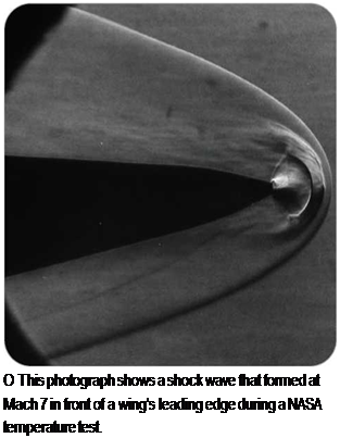
When researchers found it difficult to accelerate experimental aircraft through the sound barrier, they looked at the shape of the airplane’s wings. As a normal wing nears the speed of sound, a high-pressure shock wave forms on top

of it. This causes drag, which makes it difficult for an aircraft to go faster with­out using a lot more engine power. It also makes an aircraft harder to control.

Simply by changing the shape of the airfoil, the shock waves can be made smaller. Airfoils changed in this way are called supercritical wings. In a supercrit­ical wing, the upper surface is flattened

WINGLETS

The high-pressure air below a wing tries to flow around the wingtip into the low – pressure air above the wing. This makes the air spin off the wingtips and trail behind the plane. The spinning trails are called vortices. The vortices behind a big airliner are powerful enough to flip over a small plane flying behind it. Wingtip vortices also cause extra drag. Some air­planes have wingtips that are specially shaped to reduce the drag caused by vor­tices. Many aircraft use turned-up wingtips called winglets for this purpose.

Supercritical Wings

О The Learjet, the first jet plane in produc­tion to use winglets, found increased range and stability with this wingtip device.

EXPERIMENTAL WINGS


A few planes have been built with wings that sweep forward to increase maneuver­ability. The first forward-swept wing airplanes were built in the 1940s, but their metal wings could not be made stiff enough, and so they bent. When new materials such as carbon fiber were developed, designers looked at forward-swept wings again. An experimental jet-powered aircraft with forward-swept wings, the Grumman X-29, was built in the 1980s. In Russia, the manufacturer Sukhoi has produced an experi­mental forward-swept wing supersonic fighter, the Su-47 Golden Eagle.

The Wright brothers solved the problem of how to steer a plane by making its wingtips bend, which is called wing warping. By twisting the wingtips on one side of the plane in one direction and the wingtips on the other side in the opposite direc­tion, more lift was produced on one side and less on the other side, so the plane rolled into a turn. Since then, most airplanes have used ailerons instead of wing warping.

Today’s designers are still working on flexible wings, however. They now are called aeroelastic wings. The X-53 is an experimental plane with flexible wings. When wings bend, the result is usually more drag, which is not wanted. The X-53’s wings and the positions of its flaps and ailerons have been designed so that when the wings bend, the result is more lift. One advantage of flexible wings is that they can be up to one – fifth lighter than stiff wings. Flexible wings may enable future aircraft to burn less fuel, carry heavier cargo, or fly farther.

C With its forward – swept wings, the X-29 had a better lift-to-drag ratio than other aircraft, but not enough to be developed into a production model.


Supercritical WingsSupercritical Wings

Подпись: О The C-17 Globemaster III has supercritical wings to give extra lift to the heavy cargo plane.

and the curve at the trailing edge is increased. Planes with supercritical wings can go faster with less engine power. Although supercritical wings were developed for supersonic aircraft, they also can produce a lot of lift at low speeds, so they are used by cargo aircraft. The extra lift is good for getting heavy loads off the ground at low speeds.

German and Japanese Innovations

The V-1 was one of several innovative weapons developed by the Germans. These included the V-2 ballistic missile, anti-aircraft missiles, guided bombs, and the rocket-powered Me-163 interceptor, capable of speeds of 620 miles per hour (1,000 kilometers per hour). The Dornier Do-335 Pfeil “Arrow” was a twin-engine fighter, with one propeller in its nose and another in its tail. This unique air­plane was almost as fast as a jet, but only a handful reached the Luftwaffe before the war ended.

The Germans were the first to use remote-guided rockets, in 1943, firing HS-293 missiles against British ships

KAMIKAZE MISSIONS

As the war swung against Japan, the nation resorted to kamikaze attacks, which started in October 1944. The word kamikaze means "divine wind." Volunteer pilots crash-dived their planes packed with explosives onto U. S. Navy ships, killing themselves and creating as much destruction as possible. Japan even built a rocket-powered suicide plane, the Ohka, which was launched from a carrier plane. An estimated 3,000-4,000 pilots flew kamikaze missions for Japan, sink­ing between thirty and eighty U. S. ships and damaging many more.

German and Japanese Innovations

о Jet engines and rockets both advanced during the course of World War II, as scientists rushed to develop new and lethal instruments of war. The Japanese Ohka suicide plane, shown here, used rocket and jet technology.

in the Atlantic Ocean. Similar radio – controlled missiles, air-launched from Dornier 217 bombers, sank the Italian battleship Roma following Italy’s surren­der to the Allies in 1943.

The Japanese proved resourceful in building robust fighting airplanes, such as the Mitsubishi Zero. The Japanese, like the Germans, had no long-range heavy bombers, but in 1944 they did attack the West Coast of the United States by flying balloons carrying small bombs across the Pacific. About 9,000 balloons were launched; around 1,000 reached the United States, causing 285 recorded incidents and six deaths.

Launch and Reentry

Spaceflight became possible with the development of rockets that had suffi­cient power to break free of Earth’s gravity. To break free, a rocket must reach escape velocity, which is just over

25,0 miles per hour (40,200 kilome­ters per hour). Takeoff and reentry are the two most dangerous times in a spaceflight. Before the 1950s, some sci­entists argued that the human body could not survive the stresses of a space launch. The earliest flights by astro­nauts proved such views wrong. Astronauts have flown faster than any humans have before and have returned back to Earth unharmed.

Conventional rocket motors work both in air (for takeoff) and in space. Most rockets used to launch spacecraft are multistage vehicles propelled by chemical fuel burned in liquid or solid

form. The propellants must include oxy­gen, or the fuel will not burn, because there is no air in space.

Booster rockets provide extra thrust during takeoff. In a multistage rocket, boosters and lower stages separate and fall away as soon as their fuel is burned up. Only the topmost stage reaches space. The load a rocket lifts into space is called its payload-this could be a satellite, a manned spacecraft, or a robot space probe.

A rocket is streamlined for efficient, controlled, high-speed flight through the air. A spacecraft designed to return to Earth, like the Space Shuttle, also is streamlined, but it has wings. The wings help the Space Shuttle land like a con­ventional airplane after it has reentered Earth’s atmosphere.

Returning to Earth from space is potentially as dangerous as leaving it. A spacecraft must decelerate (slow down), using braking rockets, and approach at a precise angle so it does not hit the Earth’s atmosphere too fast. Reentry is accompanied by a rapid rise in tempera­ture. Air gets trapped in front of the spacecraft, which is moving so fast the air cannot escape. Compression (squeez­ing) of the air raises the temperature to more than 10,000°F (5,540°C). Spacecraft would burn up unless protected by a heat shield of tough, insulating material.

Working Together

The Apollo triumph persuaded many people that the United States had won

Подпись: О In 1995, U.S. Space Shuttle astronaut Robert Gibson met and shook hands with cosmonaut Vladimir Dezhurov during the first international docking mission of the Space Shuttle with the Russian space station Mir. The mission, STS-71, commemorated the Apollo-Soyuz Test Project twenty years earlier, which brought the space race to a symbolic close. the space race. No Soviets flew to the Moon, although unmanned Zond space­craft may have flown test flights for a Moon mission. Soviet plans for a Moon landing were abandoned, prob­ably because of serious problems with the rocket launcher and the lunar space­craft. The closest the Soviet Union came to the Moon was when two small robot vehicles crawled over the dusty lunar surface. Instead, the Soviets turned their attention to orbital space stations, such as Salyut 1 (1971) and later Mir. In 1975, on the Apollo-Soyuz Test Project, American and Soviet astronauts flew together in space. A new era of cooperation had begun.

By the 1980s, the space race was over. Relations between the United States and the Soviet Union improved, with the signing of treaties agreeing to bans on nuclear weapons testing and cut­backs in the production of missiles.

The United States introduced the Space Shuttle in 1981. Although they launched their Buran shuttle in 1988, the Soviets never seriously competed with the new, reusable spacecraft.

In 1989, the Soviet Union broke apart into separate countries. Since then, Russia has worked as a partner with the United States to build and operate the International Space Station. New partic­ipants in space include the European Space Agency (ESA) and China. (China became the third nation to launch an astronaut, in 2003.)

The space race provided significant technological spin-offs (especially in electronics) and led to an increase in sci­ence education. A future space race might be a commercial contest between companies offering space tourism, but most people believe that the future of scientific space exploration lies in inter­national cooperation rather than in a race for the stars.

SEE ALSO:

• Apollo Program • Astronaut

• Gagarin, Yuri • Glenn, John

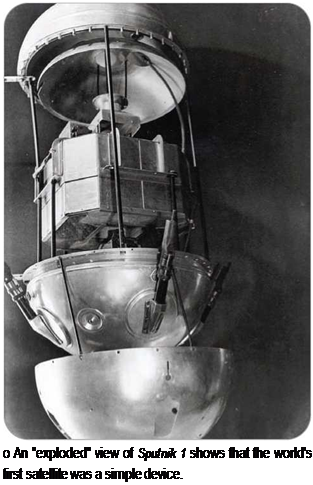
• Spaceflight • Sputnik

Подпись: ~Подпись: ГV.

Directional Stability

Directional stability keeps a plane flying in a straight line without veering to one side or the other. Early airplanes had lit­tle stability. The pilot had to concentrate extremely hard and constantly make adjustments to keep the plane under control. A gust of wind or a careless maneuver could send the plane spiraling to the ground. Many early aviators died in crashes caused by poor stability and control problems.

A modern plane’s tail fin, or vertical stabilizer, helps to provide directional stability. If the plane’s nose is pushed to one side by a gust of wind, the airflow around the tail fin moves the tail back in line with the nose, so that the plane keeps flying in the same direction instead of veering off course. (Weather vanes keep pointing into the wind for the same reason.)

Testing and Using SVS

Подпись:
Testing and Using SVSПодпись: The TIFS aircraft is a modified C-131 Samaritan military aircraft, which is itself based on a Convair 580 turboprop airliner. It was built in the 1950s and converted to a flying simulator in the late 1960s. TIFS has two cockpits. One is used to test new developments. The other (standard) cockpit can take over at any point if necessary. This double cockpit is an important feature, because it allows a test pilot safely and repeatedly to push a system all the way to failure, which is risky to do in a conventional flight test, especially near the ground. The research cockpit can be programmed to make the plane fly like other kinds of aircraft. In its test flights, it has doubled for a variety of airliners, experimental aircraft, the B-2 Spirit stealth bomber, and even the Space Shuttle. As well as simulating other aircraft, it also is used to test new avionics systems. In this case, the second cockpit can be replaced by a nose section containing the new avionics, and the research pilot sits at a crew station in the aircraft's cabin. Pilots say it is more realistic to fly TIFS than a simulator on the ground because it sounds, feels, and performs like the real airplane. The TIFS plane entered service as a military transport on March 22, 1955, so it cele-brated its fiftieth anniversary in 2005. к J
In 1999, synthetic vision was tested in flight by a modified C-131 military aircraft named the Total In-Flight Simulator (TIFS). For the tests, TIFS was fitted with screens to try a variety of dif­ferent images and data. The research flights were made out of Asheville Regional Airport in North Carolina.

Подпись: О A pilot testing SVS in 1999 was able to compare the virtual world on his screen with a view from the cockpit.Testing and Using SVSПодпись: — SEE ALSO: Testing and Using SVSResearch pilots using the synthetic vision system reported that they soon forgot they were looking at a computer-generated image and not at the real world.

System designers are already thinking about other ways in which SVS might be used in the future. One possible application is in air traffic control systems at airports.

Airport traffic con­trollers work in a con­trol room that looks out across the airport, but some parts of an airport may be obscured by buildings or bad weather. SVS could provide con­trollers with a clear, computer-generated view of the entire air­port in all conditions. Although synthet­ic vision has been developed for civil aviation, military forces also are interest­ed in the systems. Synthetic vision already has been flight tested in military airplanes and helicopters.

• Air Traffic Control • Avionics

• Cockpit • Global Positioning System • Pilot